3. Computer-Controlled Cutting
We had a precise and exciting lecture from Daniele Ingrassia and Debabrata Goswami about Computer-Controlled Cutting.
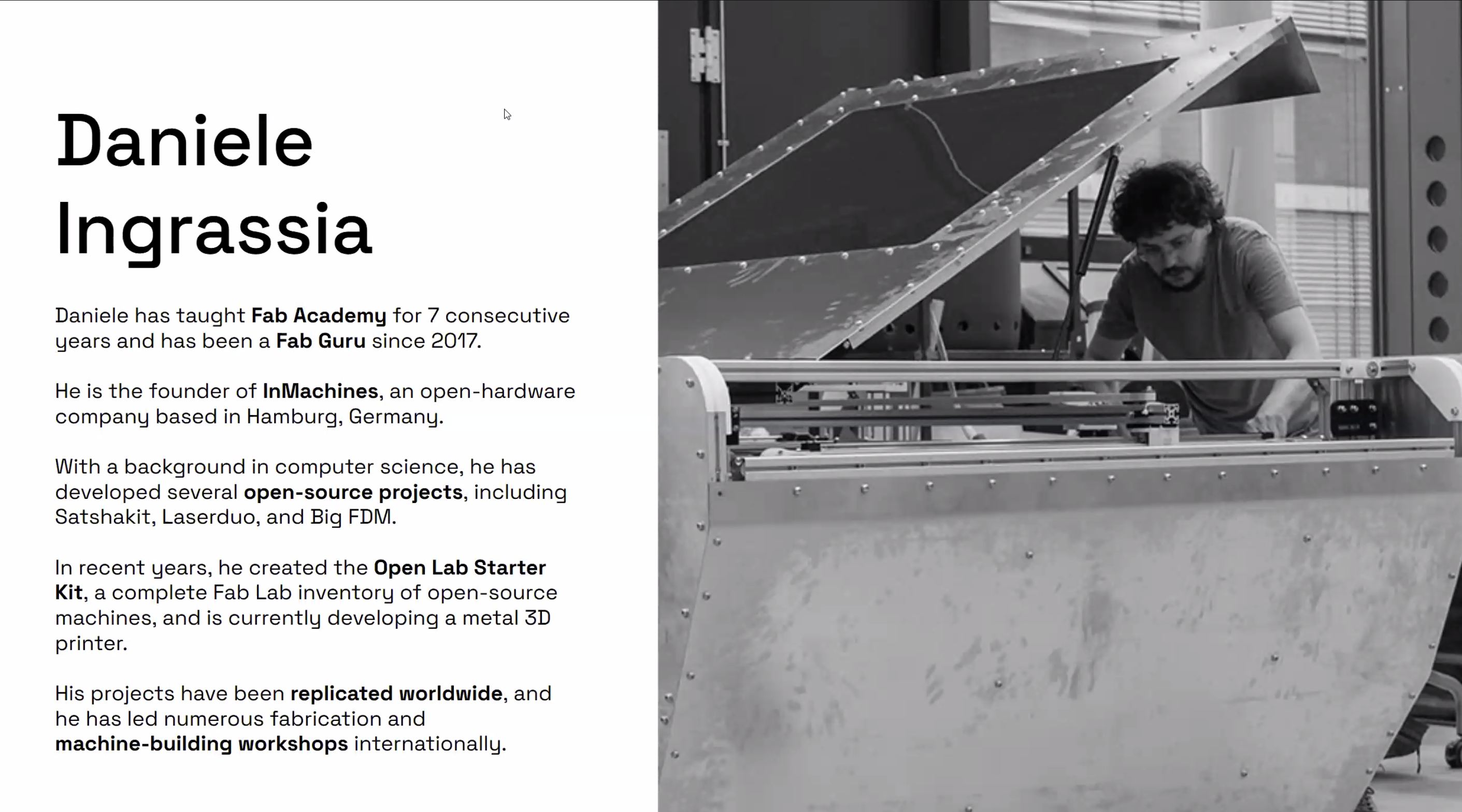

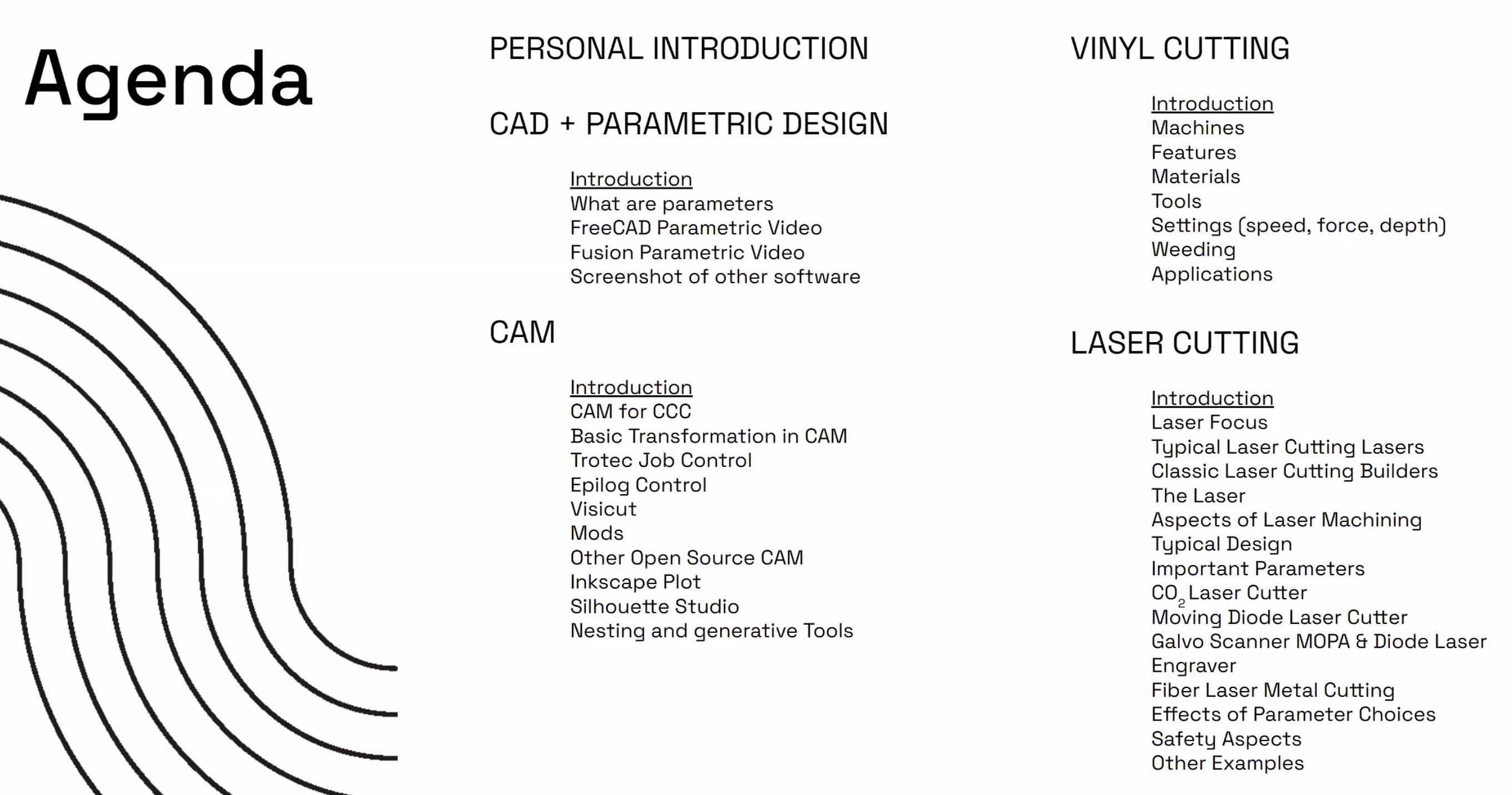
Especially Daniele’s lecture about parametric design was very useful by showing practical way of sketch designing.
Assignments and Assessment this week
Computer-Controlled Cutting
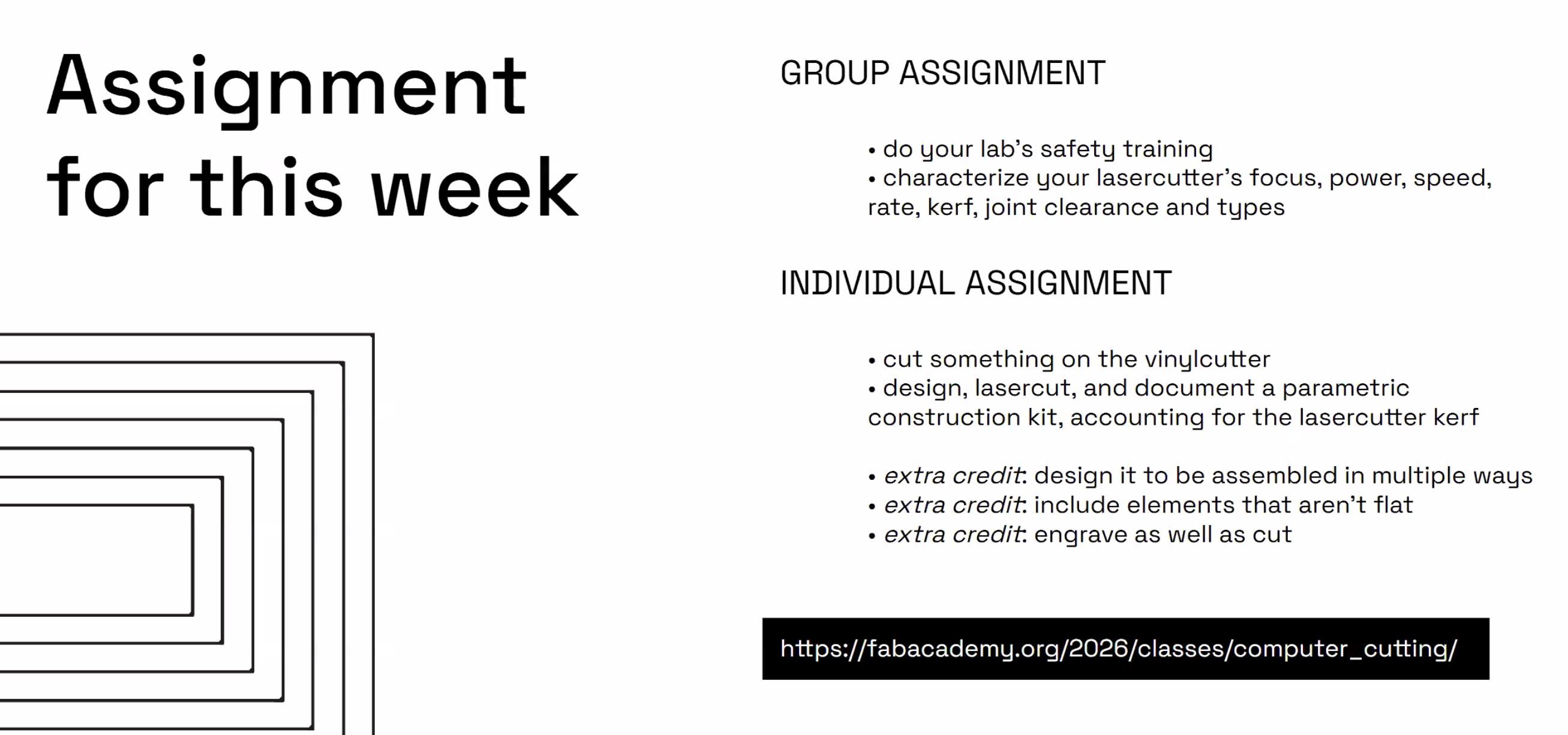
- Group assignment:
- Do your lab’s safety training
- Characterize your lasercutter’s focus, power, speed, rate, kerf, joint clearance and types.
-
Document your work to the group work page and reflect on your individual page what you learned.
-
Individual assignments
- Design, lasercut, and document a parametric construction kit, accounting for the lasercutter kerf.
- Cut something on the vinyl cutter.
Learning outcomes
- Demonstrate and describe parametric 2D modelling processes.
- Identify and explain processes involved in using the laser cutter.
- Develop, evaluate and construct a parametric construction kit.
- Identify and explain processes involved in using the vinyl cutter.
Have you answered these questions?
- Linked to the group assignment page.
- Reflected on your individual page what you learned of your labs safety training
- Explained how you created your parametric design.
- Documented how you made your press-fit construction kit.
- Documented how you made something with the vinyl cutter.
- Included your original design files.
- Included hero shots of your results.
Group assignment
–> Go to Group assignment page
Learning Point from Group Work
- Check the Operational Window if “the Value” you set is reflected.
–> We had several laser cutting by changing parameters but laser cutting condition never changed. This happened because of the “Parameter Setting” file was not recognized by the “Operational Controller” due to the file name written in “Japanese Character”. I as an operator should have checked the value that was indicated in the Operational Window.
Individual assignment
Design one part of small model of my final project with parametric design.
I modified the developing next version of FABLAB.able Kinetic Seat model into Carton Board modeling. How I modified is documented in NDA folder for confidential reason.
Bottom Cushion Back Beam designed for carton board model with parametric design.
Bottom Cushion 2nd-4th Back Beam designed based on above model
Upper slot point is a little bit outer than above design.
Back Beam part for carton board locates in thi position.
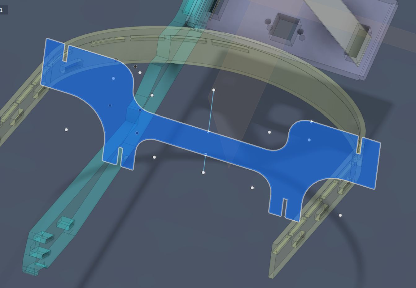
Extrude carton board thickness (3mm) the Beam sketch for designing Seat Surface Frame.
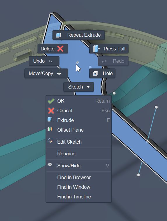
Now I need to design 2nd Back Beam referring to the current one but a little bit different at the top slot position.
First, I tried with making a copy by moving frontward the current sketch. However, it is considered as one sketch even sketch lines are doubled.
I thought this is not a good idea.
Then I asked ChatGPT by sharing above screenshot the way to make a little modification referring to the base sketch.
I had an instruction to use “Project” function by pressing “P” button while choosing the I want to make new sketch.
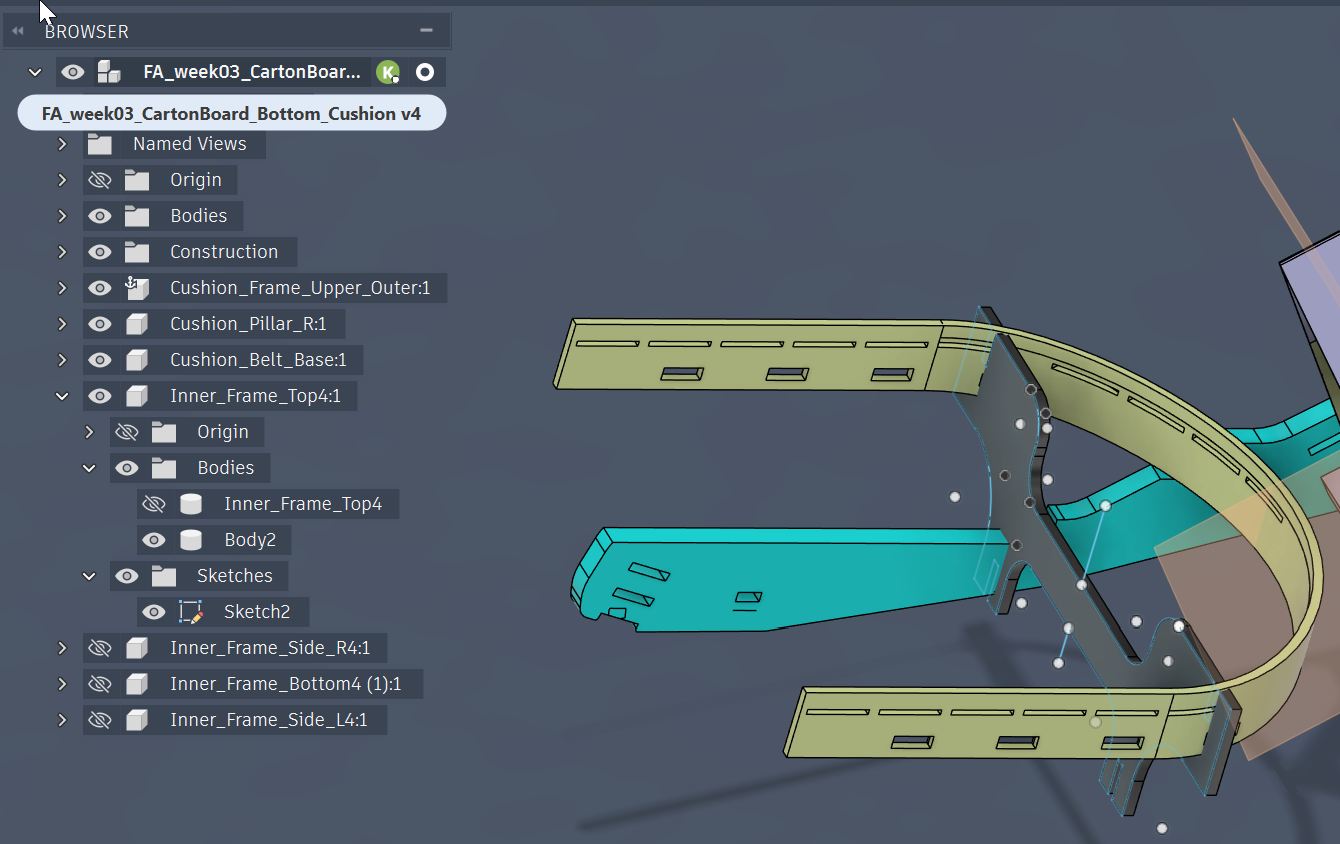
I made 2nd Beam layer in front of the current beam.
“Create Sketch” on the new plane and press “P” key to make project referring to the current beam.
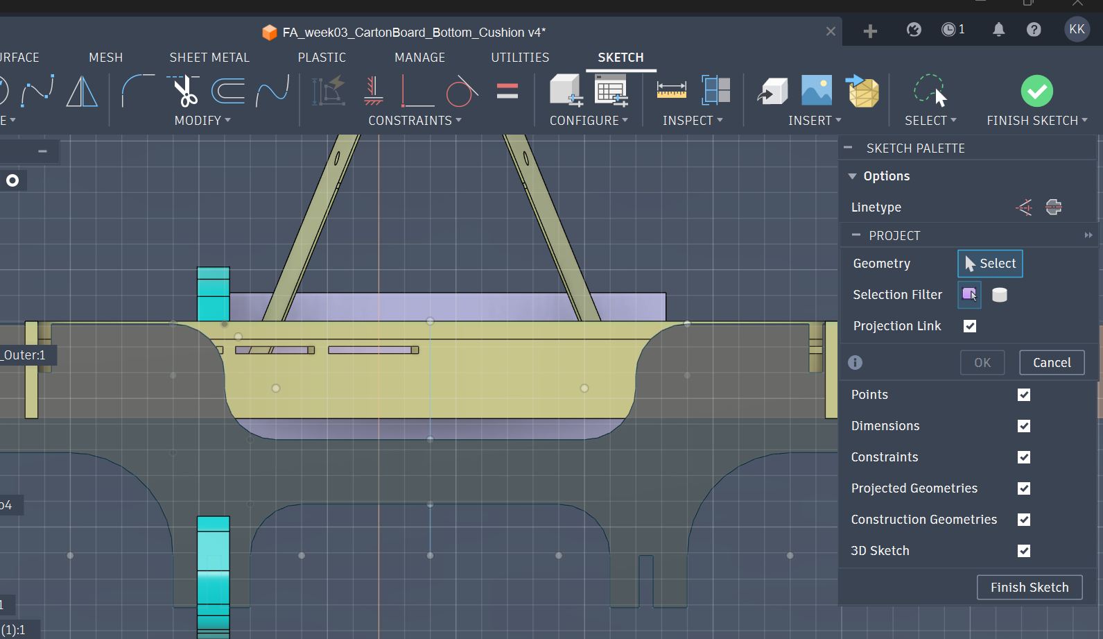
Select objects (“lines” in this case) to project (means copying to other layer with projection link).
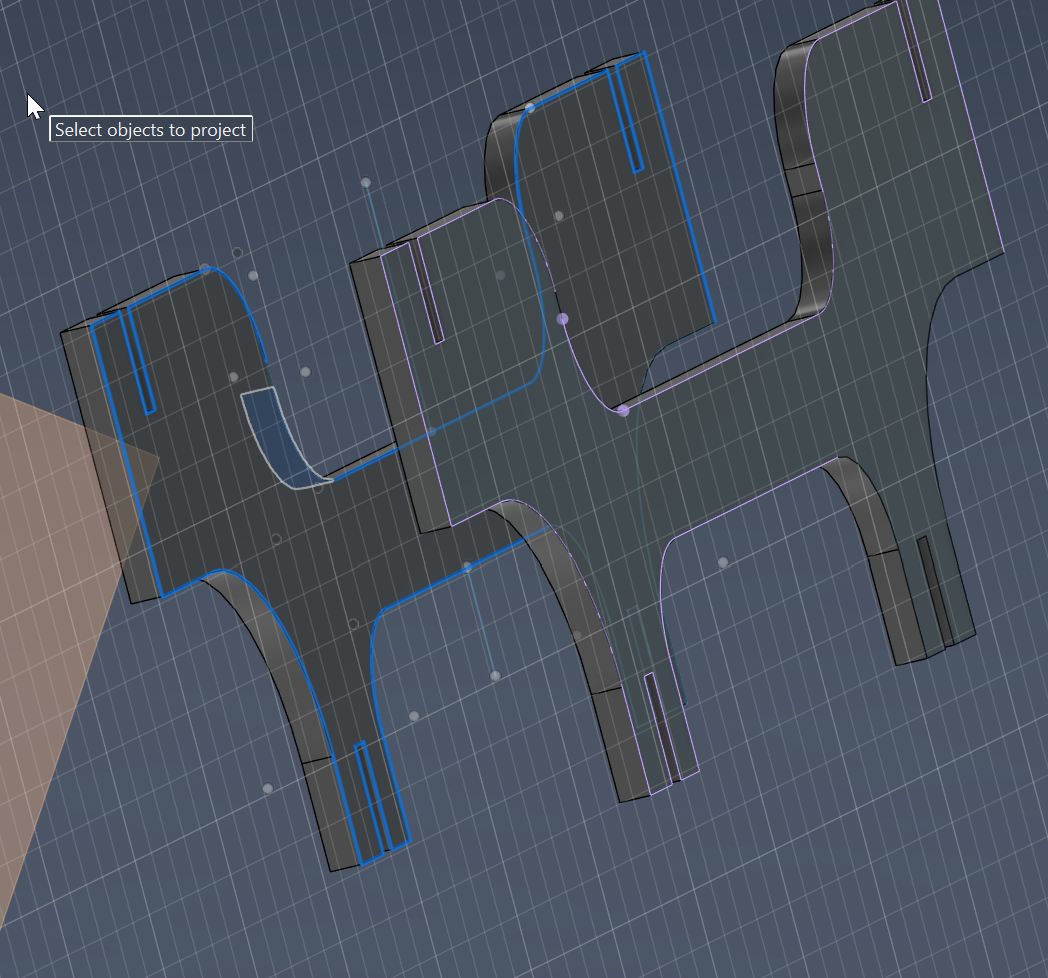
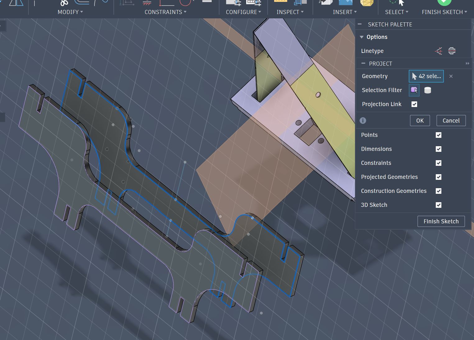
All objects (lines) are selected to project.
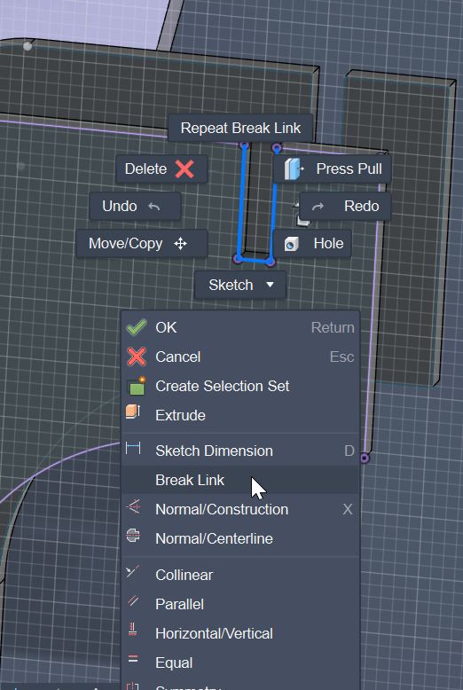
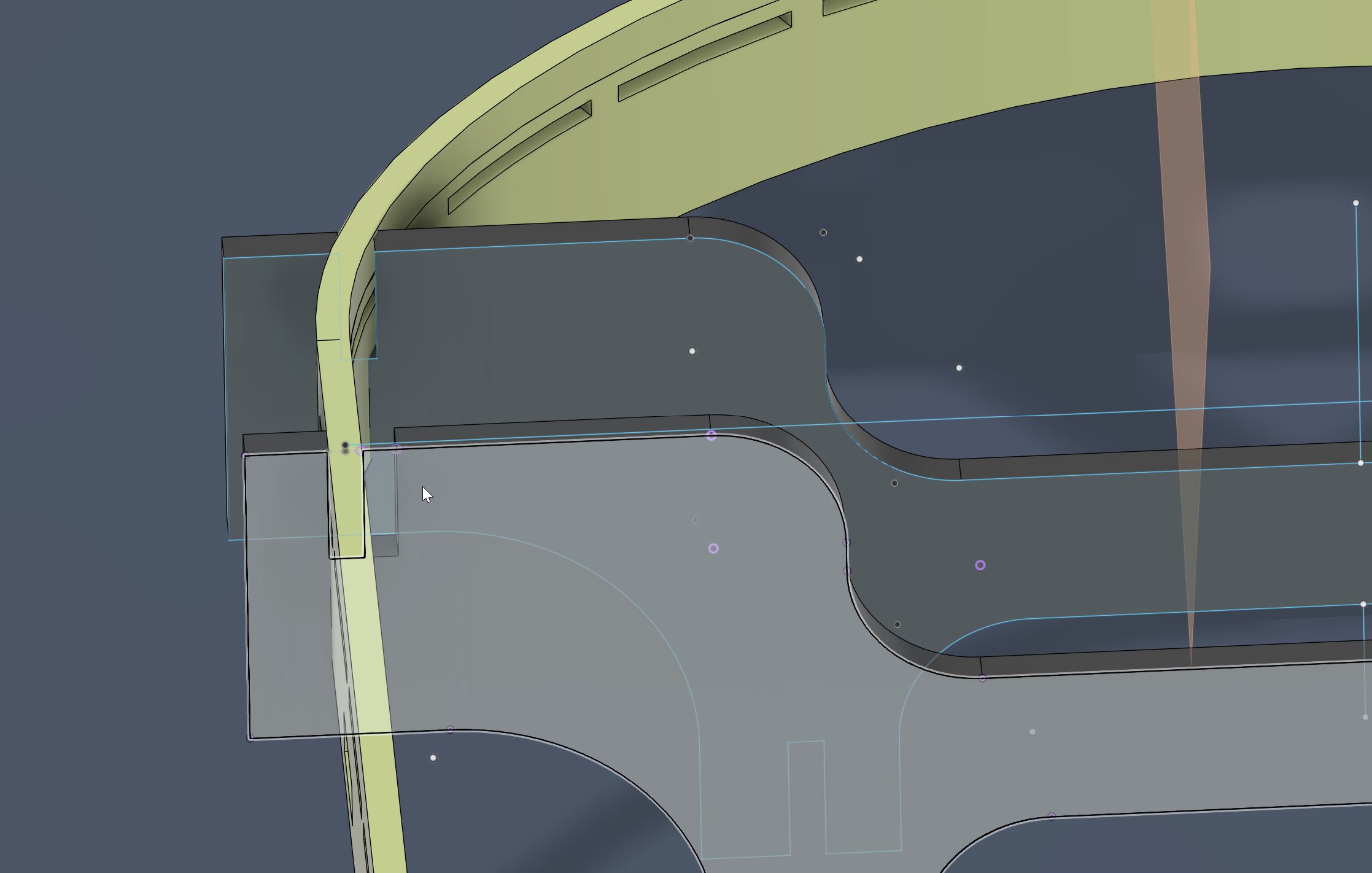
For the part that I want to modify from the referring sketch, choose the part and right click to select “Break Link”.
Modify sketch in 3D with the other part sharing the connection slot.
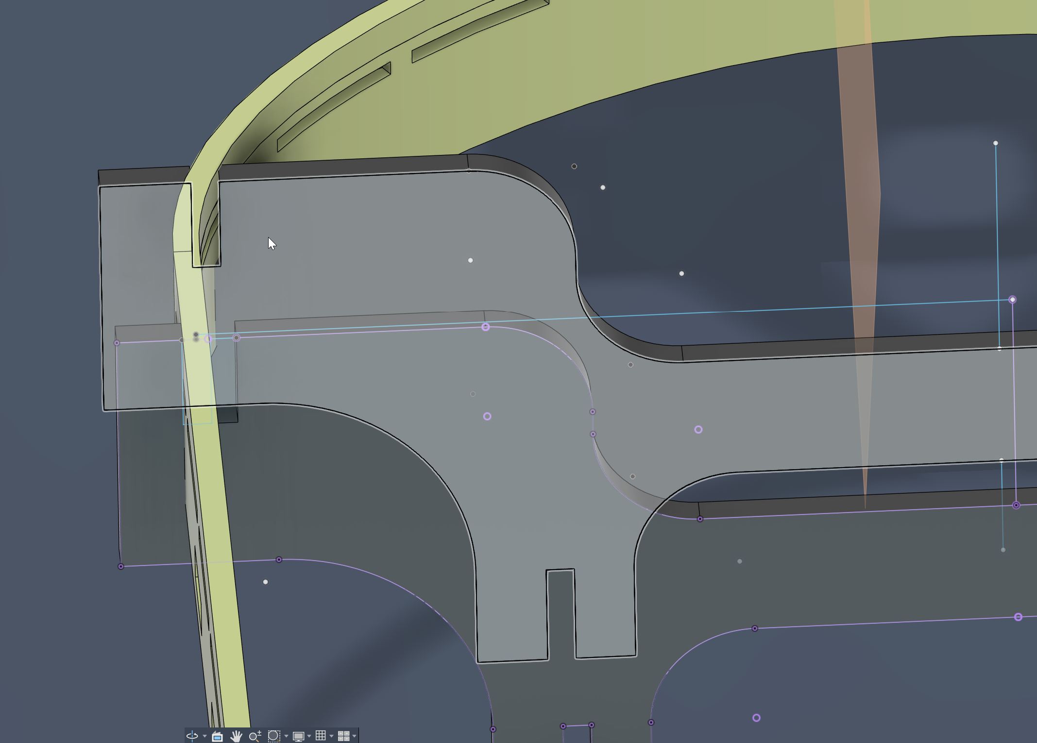
Modified slot for Surface Frame connection.
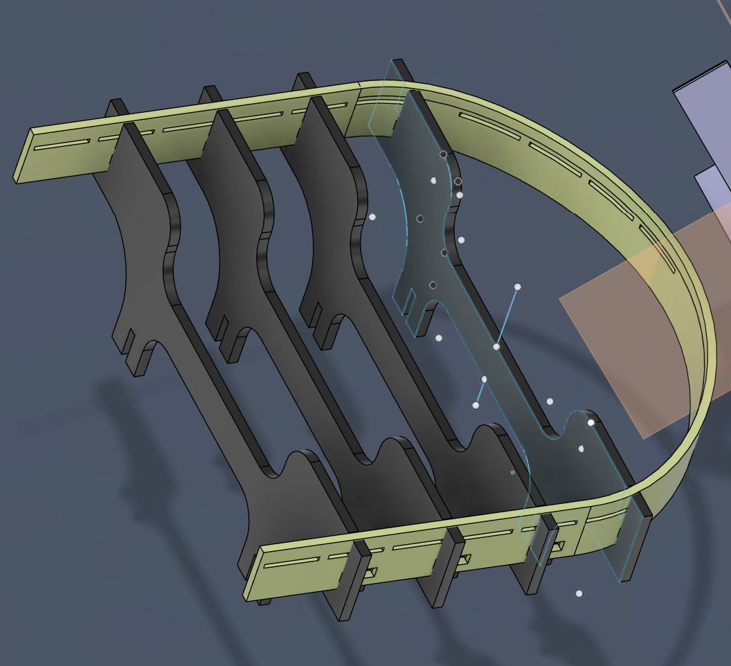
Copied this beam for two more beams in frontward.
To design connection slot for Surface Frame, I used beams’ slot to make Boolean cut.
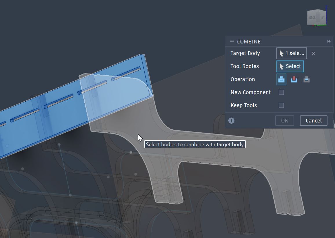
Select Boolean cut with “Keep Tools” setting.
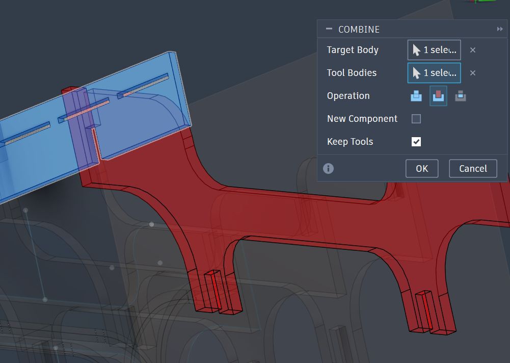
Slot is made by Boolean cut.
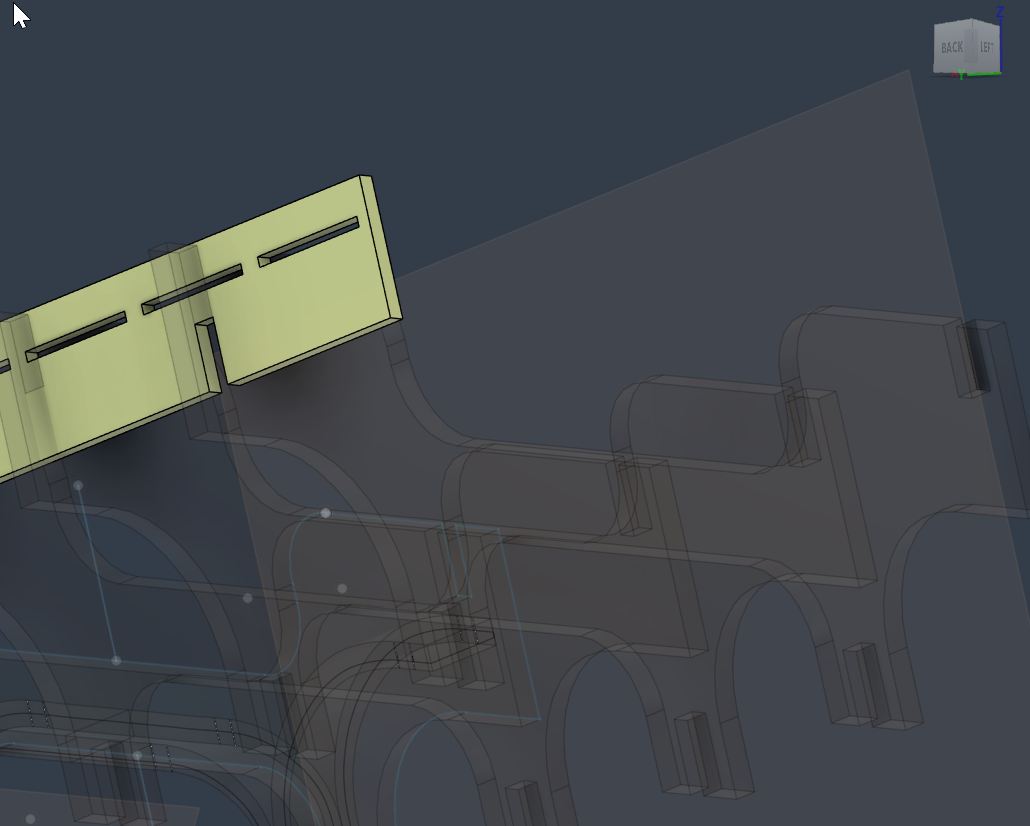
Slots for other Beams were Boolean cut by each Beam.
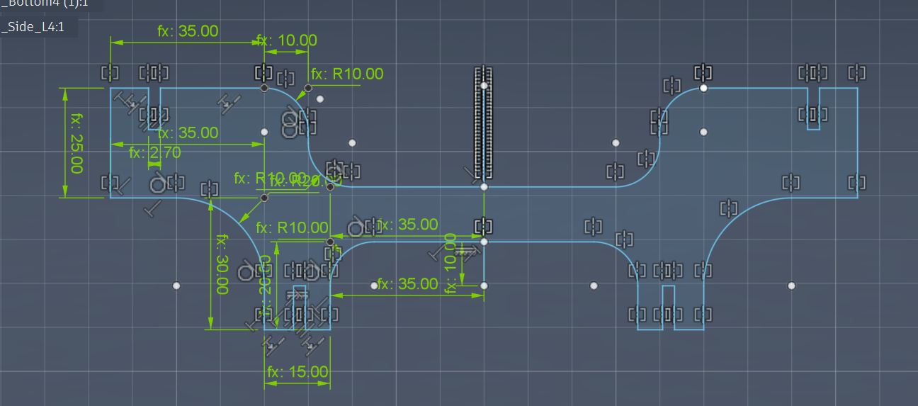
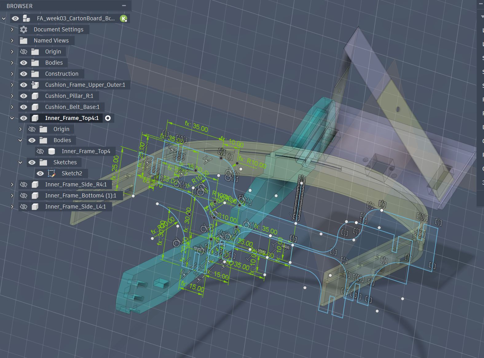
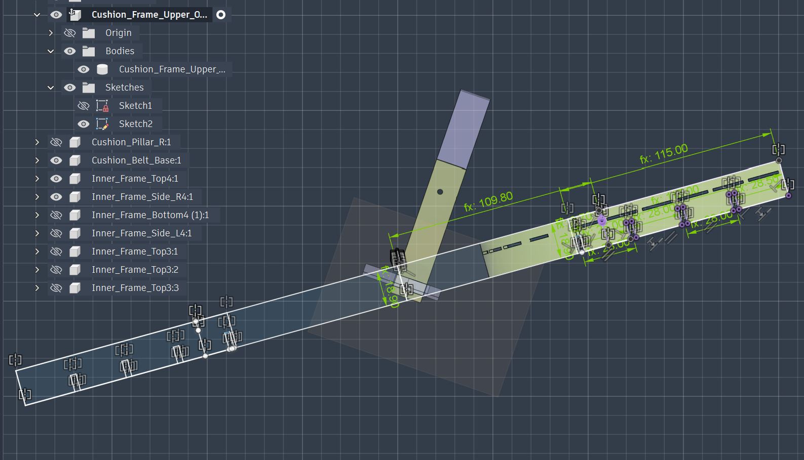
Now, I design a parametric sketch referring the Seat Surface Frame 3D model.
Create Sketch at the side surface of the Frame.
Create Sketch with parametric design.
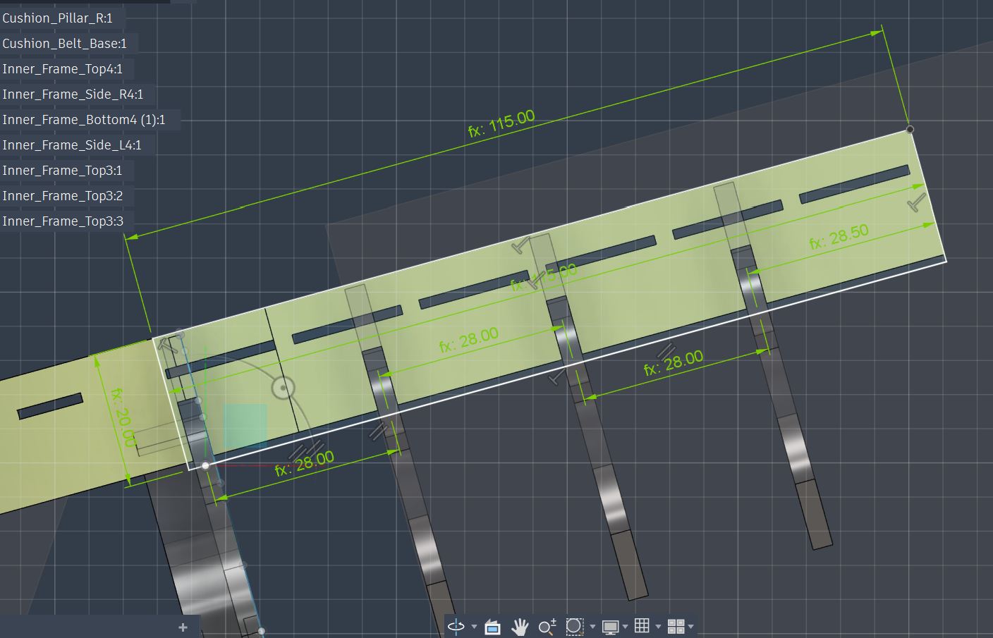
Slot design with center rectangle to meat the position of each parametric designed pitch line, but failed…
The 2D design rectangle cannot meets the angle that I referred from the 3D model…
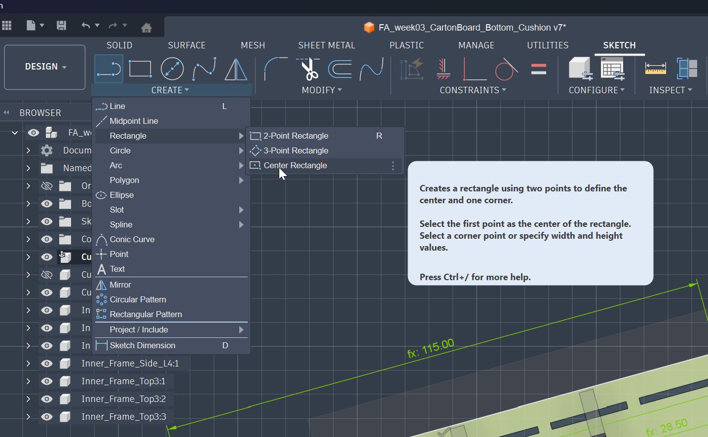
I had to go for the different way to draw the slots in angled sketch.
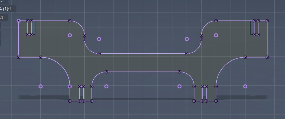
Then I tried “Projection” from the 3D model to draw 2D Slots in the Sketch.
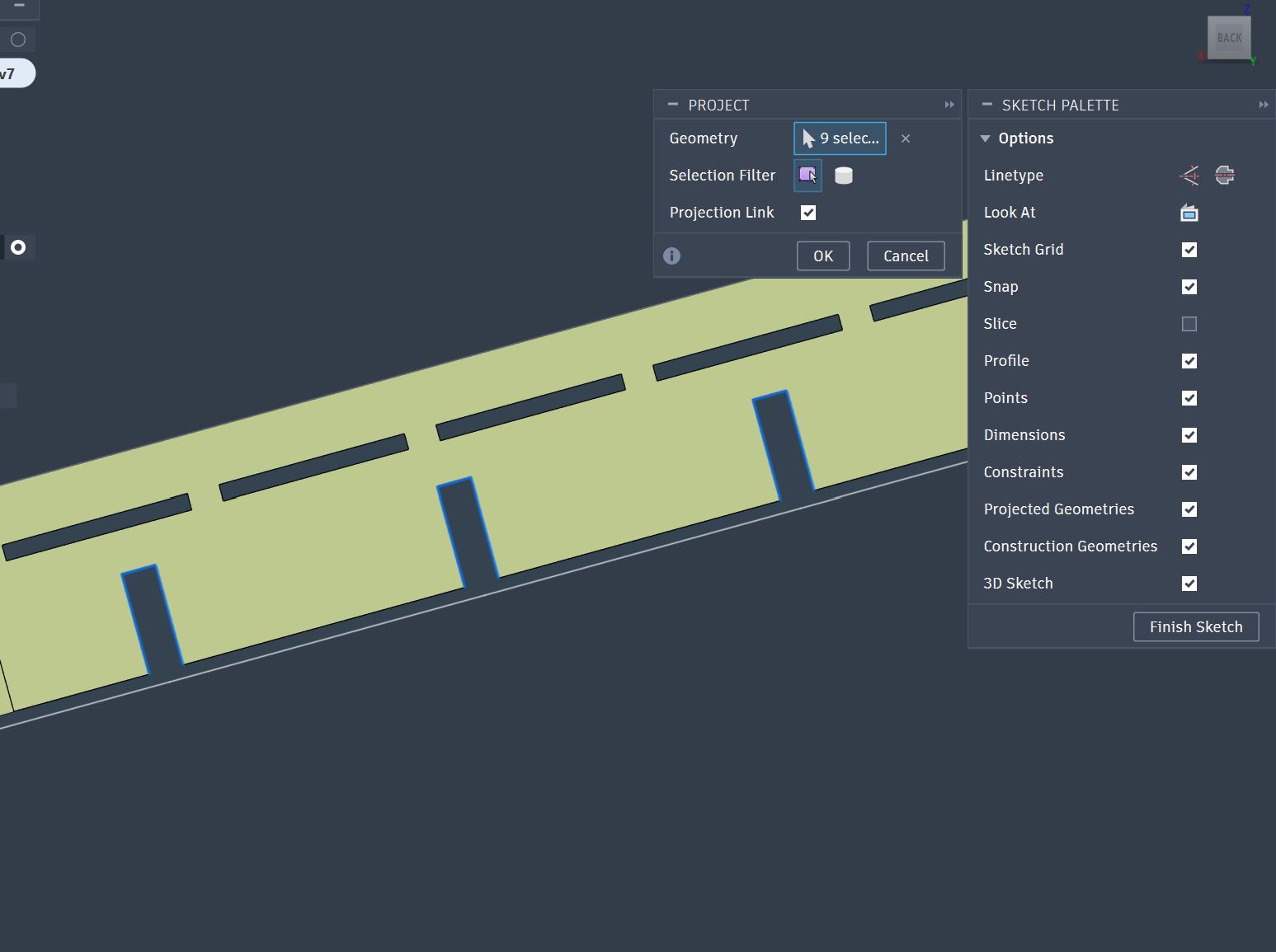
I need to add one more slot manually since it is not in the same surface with other three slots.
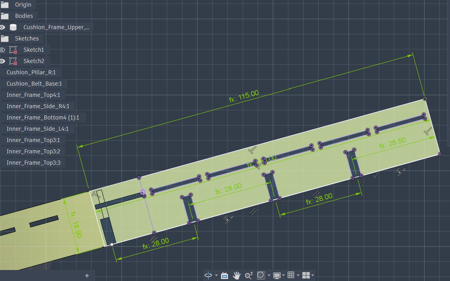
One slot in a radial part need to be designed.
The length of the radius could be measured as 111.775mm
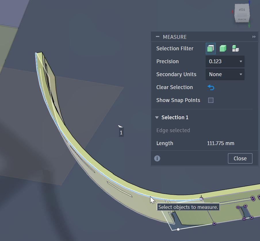
Outer radius length: 111.75
Inner radius length: 107.85
In the middle: (111.75 + 107.85)/2 = 109.8
I consider this as the length of the radius.
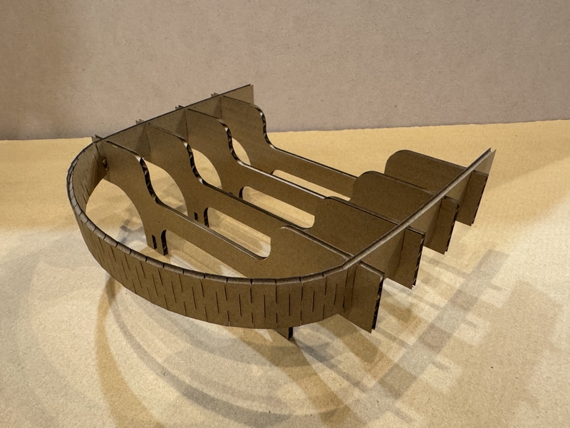
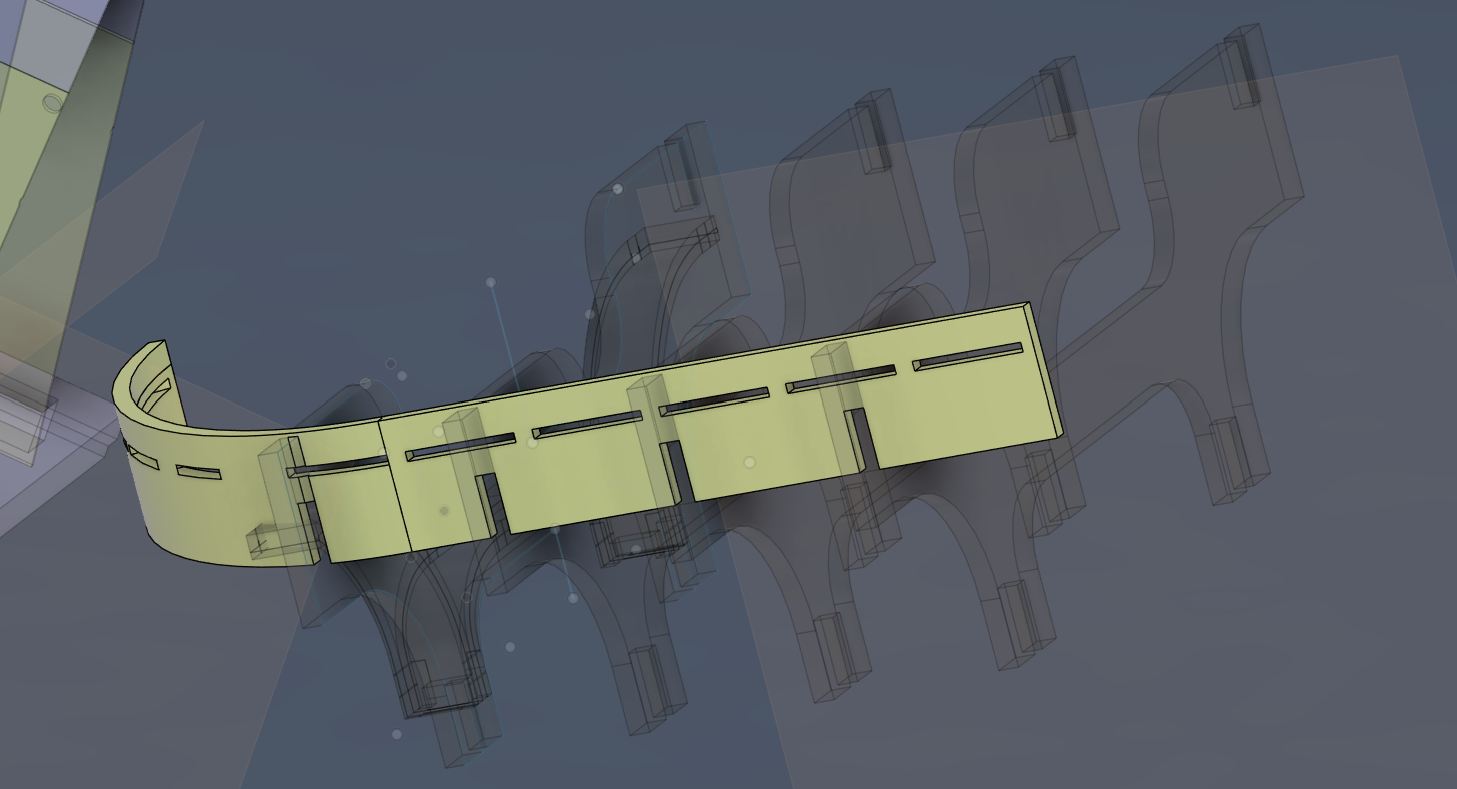
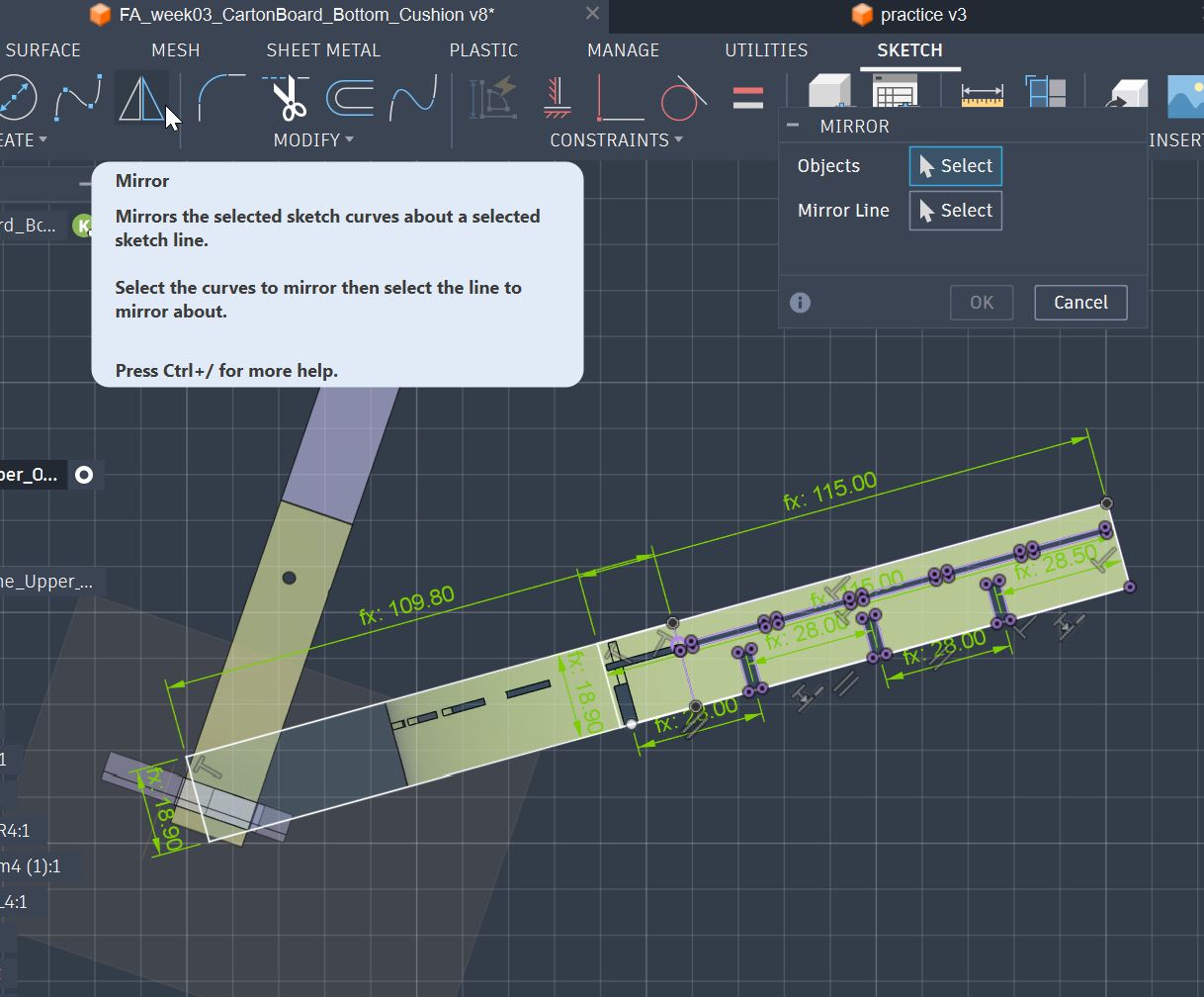
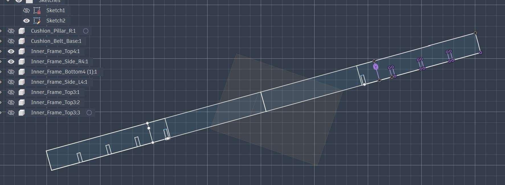
Now, I design the straight carton board part which will be bent with Kerfing to be structured as the surface frame.
Half part of the Surface Frame with straight condition
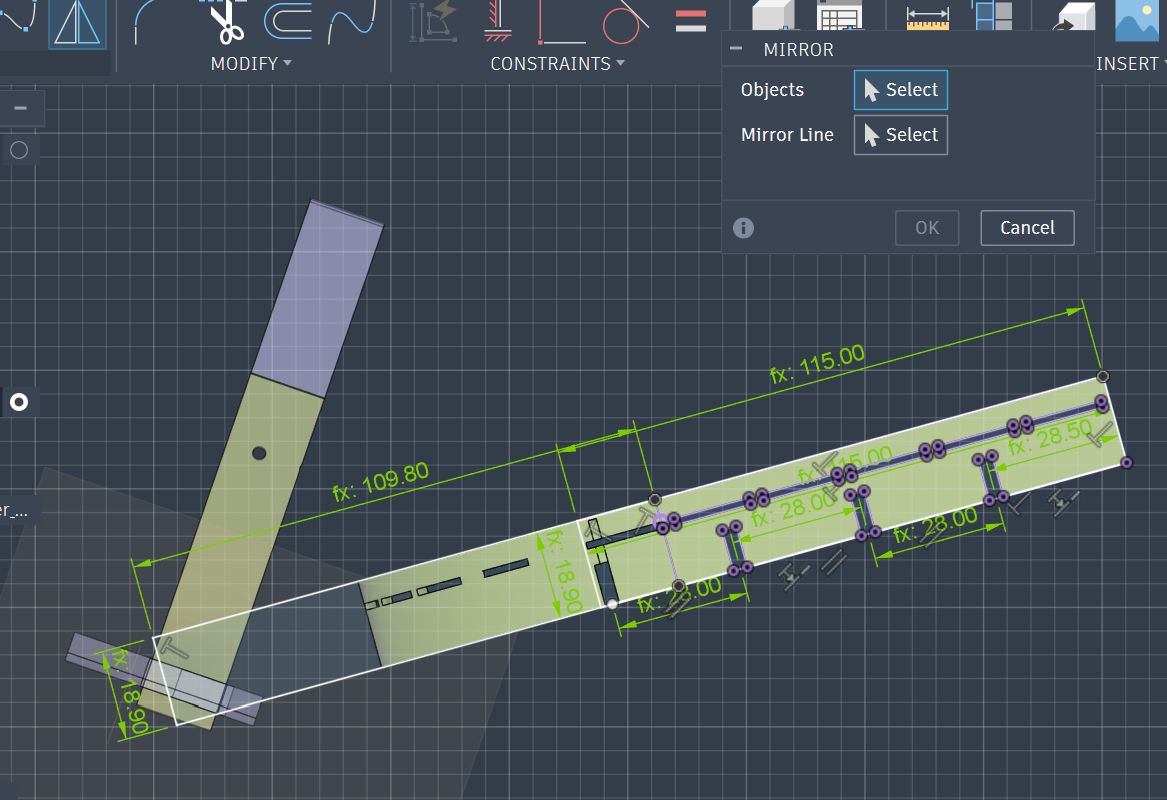
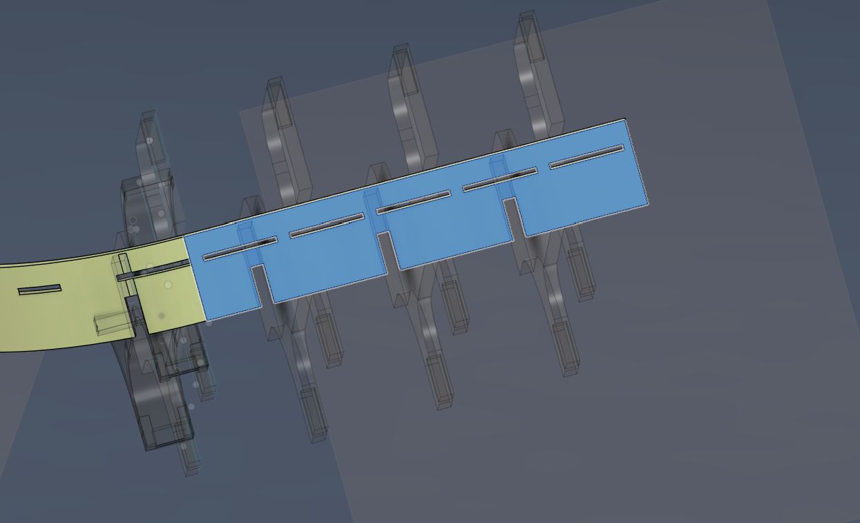
Set mirror function for making whole part of Surface Frame.
Select all objects to mirror for mirroring at the center of this part which is left edge.
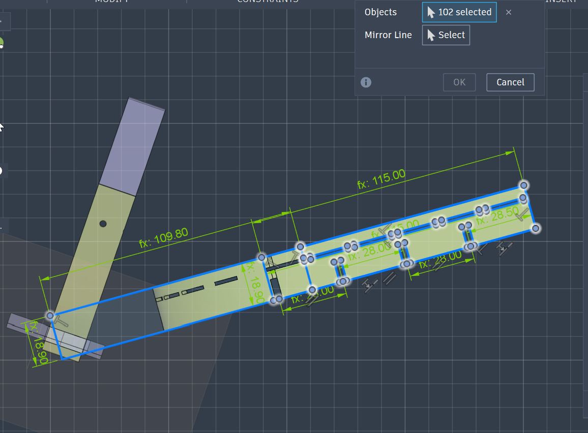
Did mirroring and got the whole part as straight condition.
Sketch of the whole length of Surface Frame part
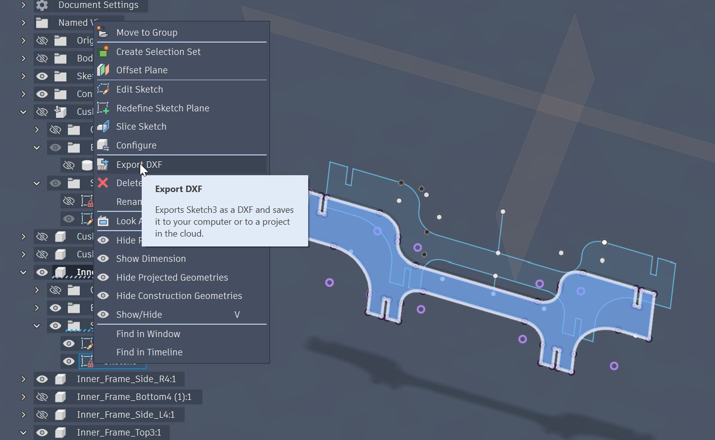
Export the Sketch to DXF file which can be read by Illustrator for Laser Cutting preparation.
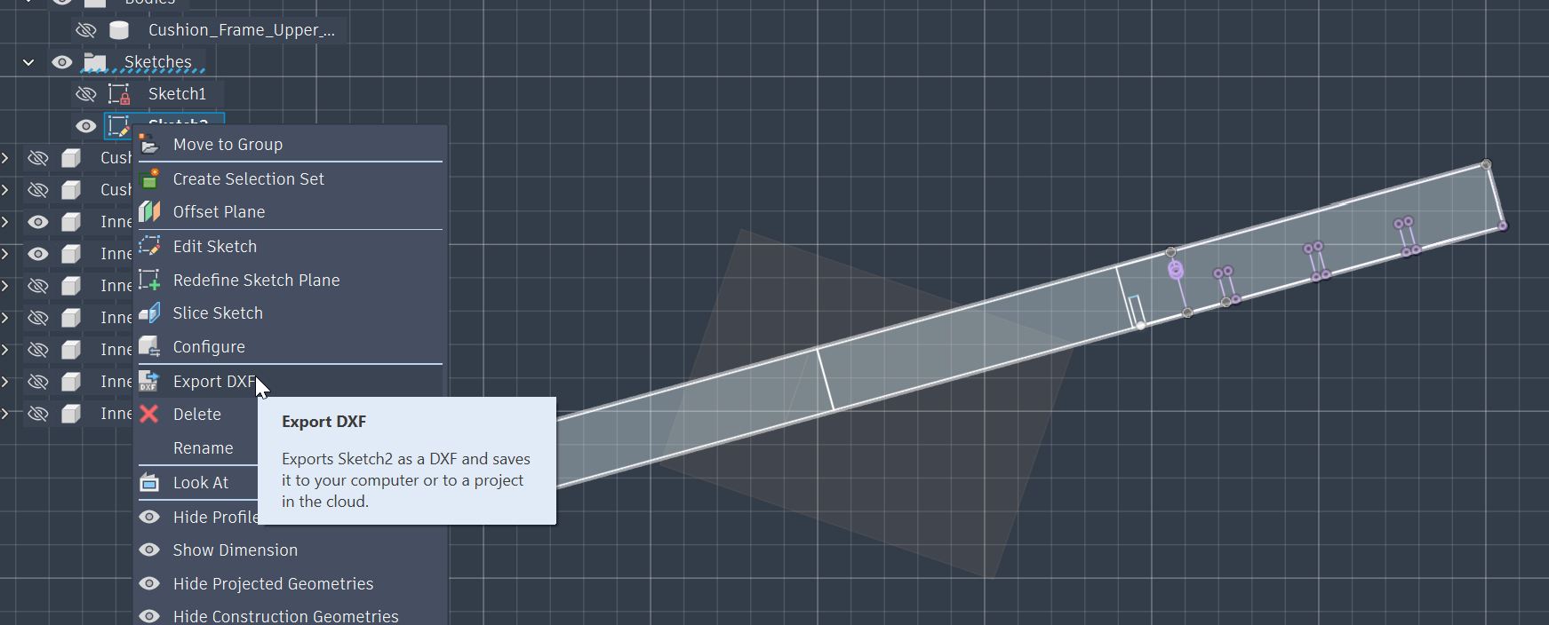
Exporting the sketch file to DXF file.
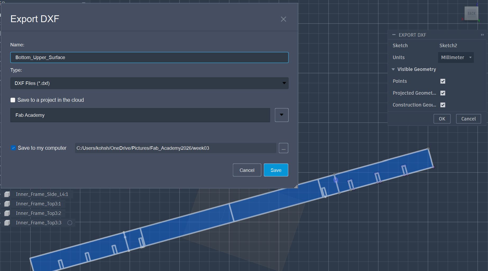
Export the rest of the part also to the DXF file.
Laser Cutting the part
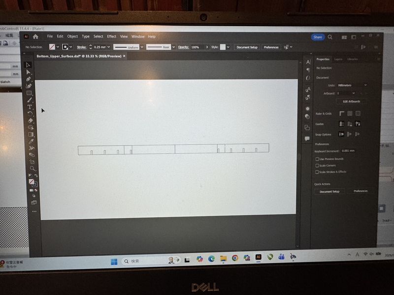
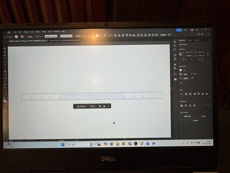
Transferred the DXF file into Laser Cutter control PC, and open the file with Illustrator.
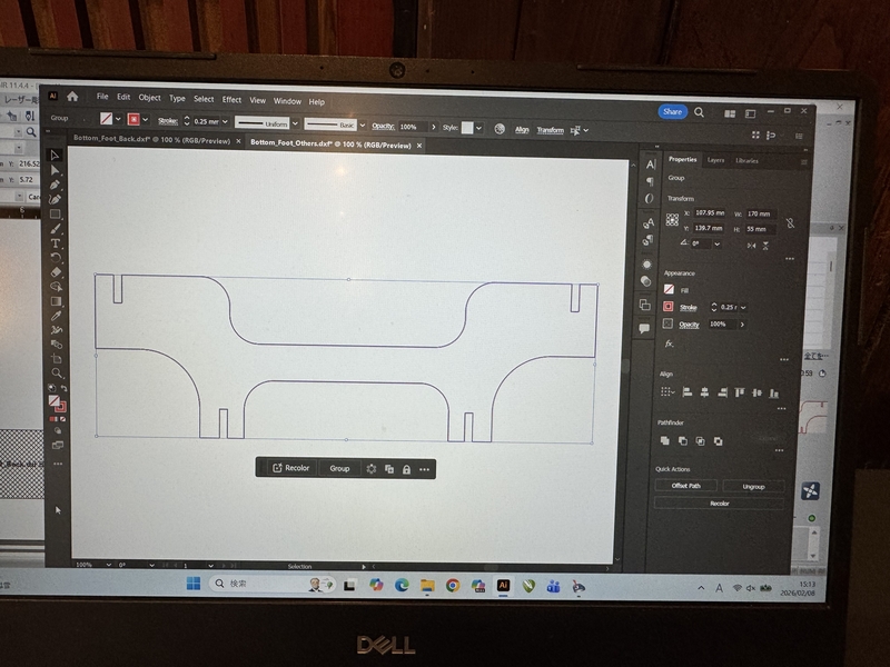
Changed the line color into RED for cutting.
Laser Cut the Bottom Beam part
Since the part length is longer than the working area of default setting of Illustrator, this setting need to be changed.
Click “Edit Artboards” to change the working area.
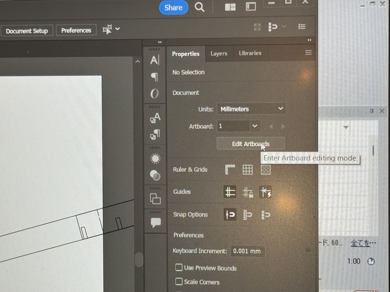
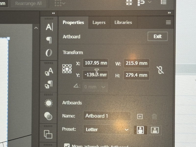
This was the default setting of Illustrator.
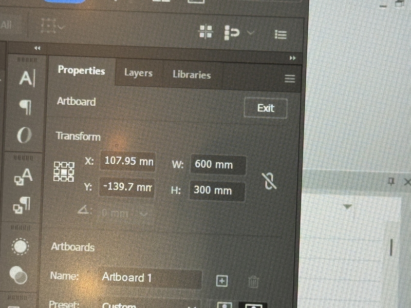
Change the values into W=600mm, H=300mm
So that the working area matches the sie of Laser Cutting area of Trotec.
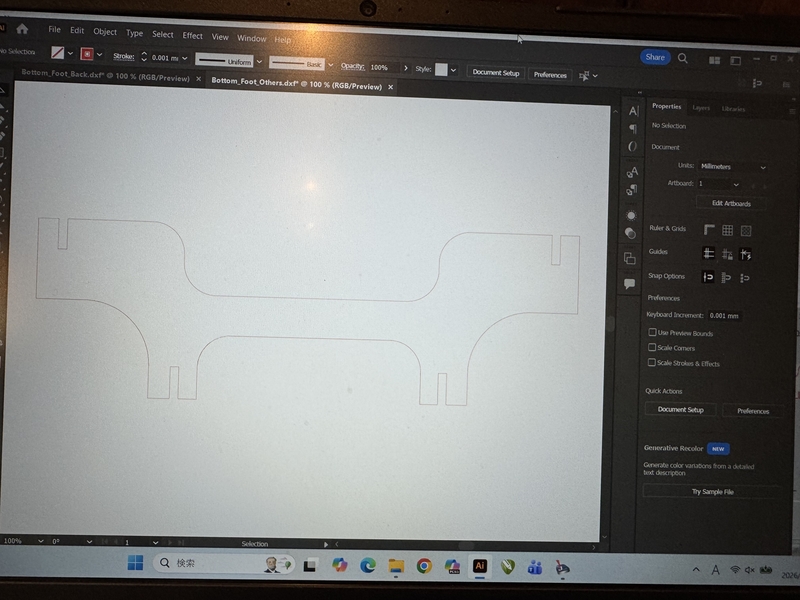
The initial drawing data has some angle due to the 3D model referred design. In order to minimize the cutting board area, I needed to modify the angle to horizontally flat.
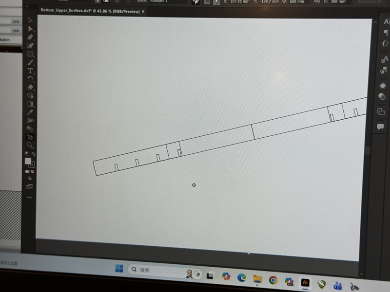
Corrected the angle into horizontally flat.
I imported a Kerfing design from net into this drawing to merge.
Living Hinge data picked from Trotec information page
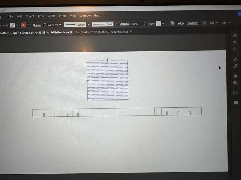
Rotate the Kerf Design for 90 degree for the bending function.
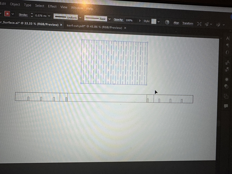
Modified the pitch by spreading the width.
Modified the design with supporting lines.
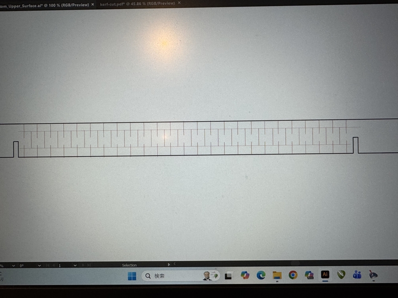
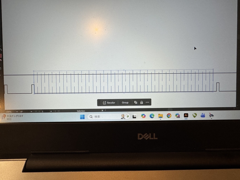
Kerfing design was merged.
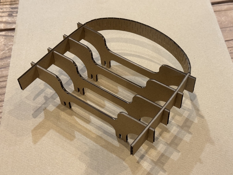
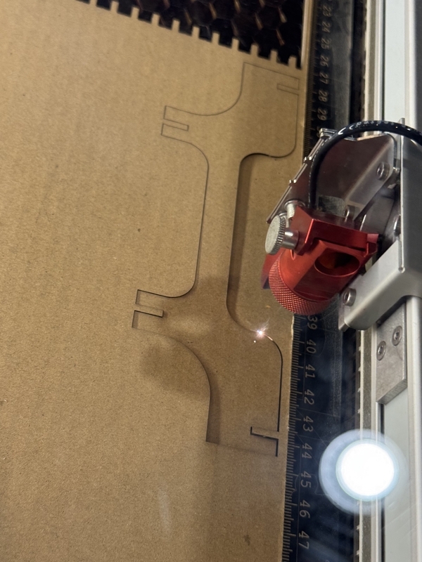
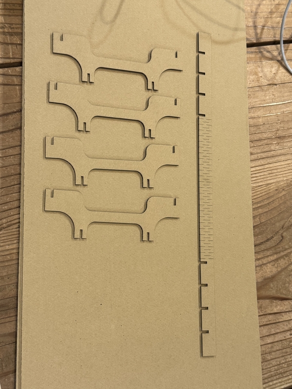
Laser cut with the same condition of our Group Work condition.
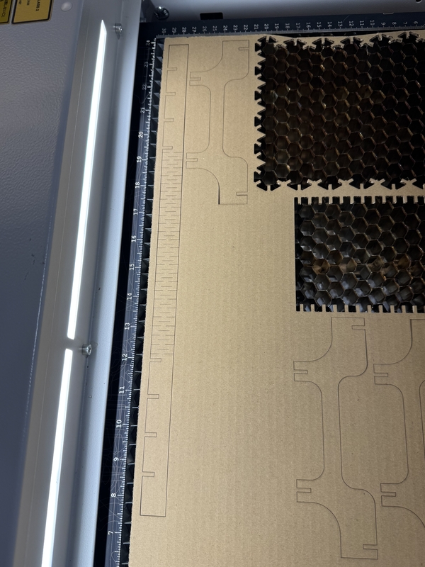
Here under picture shows the Laser cut parts.
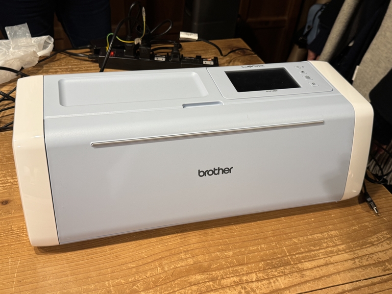
Experiencing Vinyl Cutter
Vinyl Cutter in FABLAB Kamakura
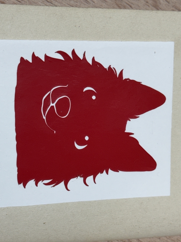
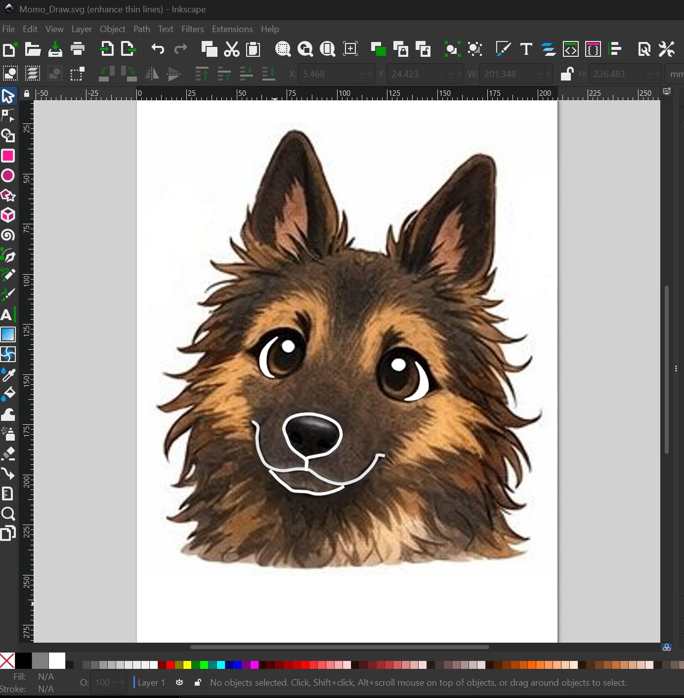
I wanted to make a sticker of my dog’s exaggerated face from following photo.

I asked Chat GPT to draw my dog’s exaggerated face line stamps, and got following stamps, and got following Stamps drawings.
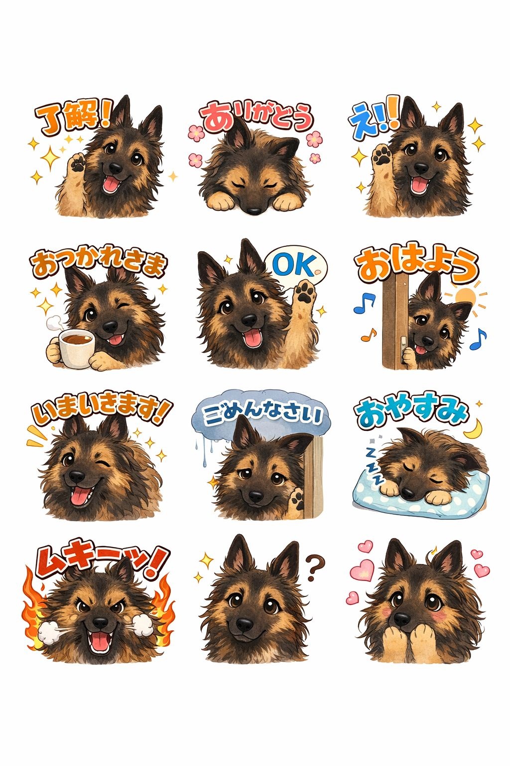
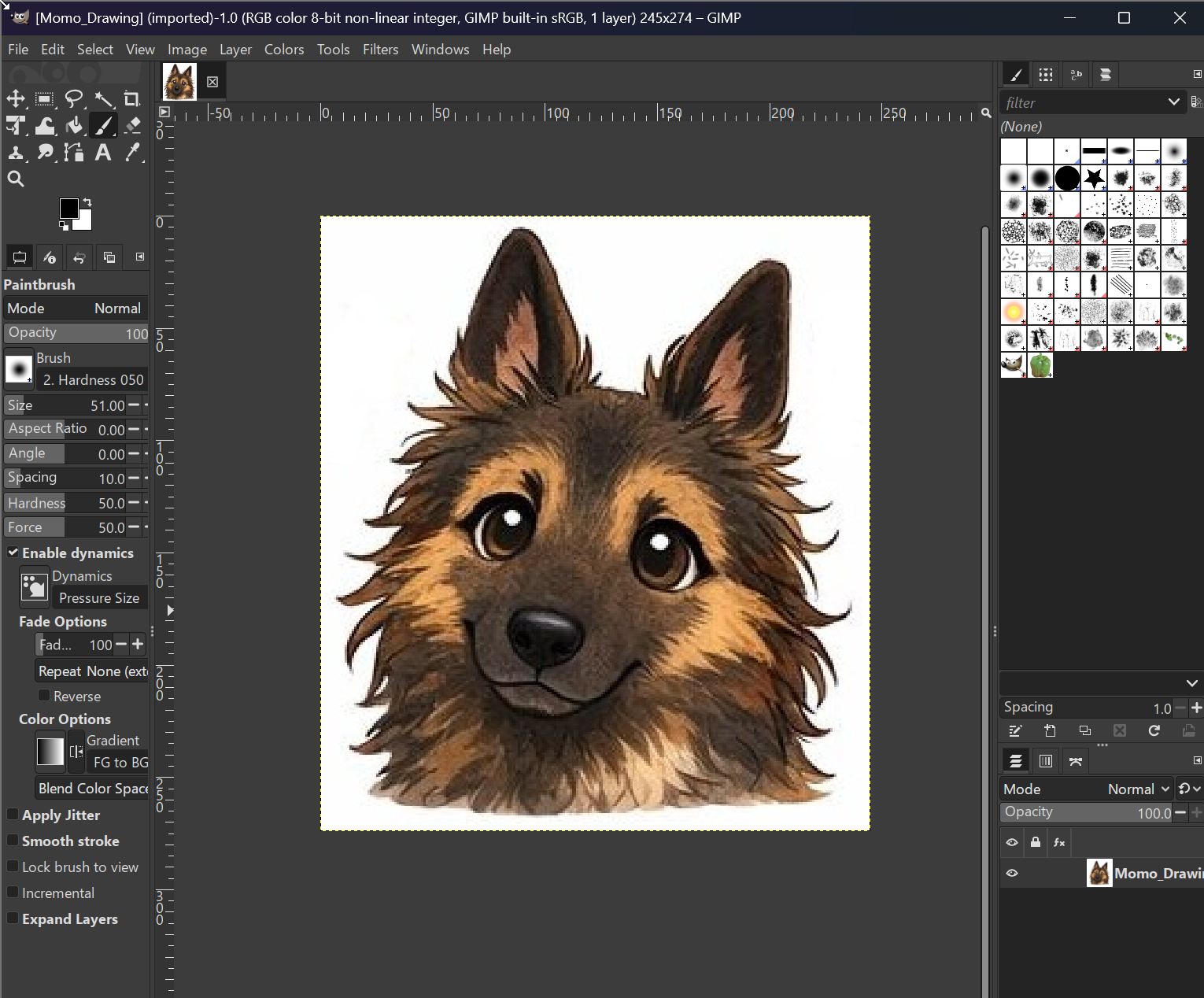
I selected following picture for Vinyl Cutting.

Opened the picture by InkScape.
Select “Trace BitMap” in “Path” menu.
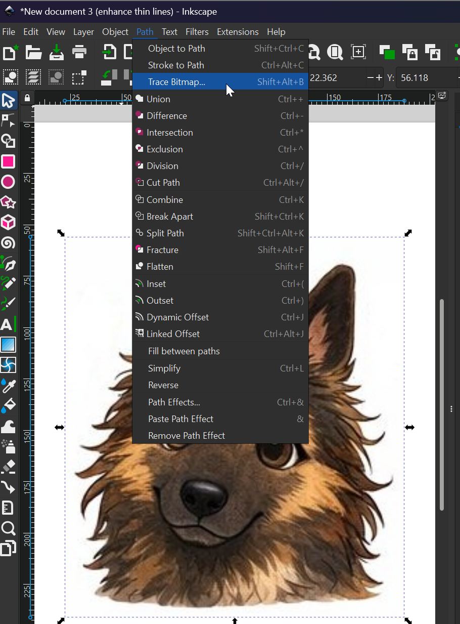
Trace adjusting “Threshold level” as 0.225 in BitMap menu, got following result.
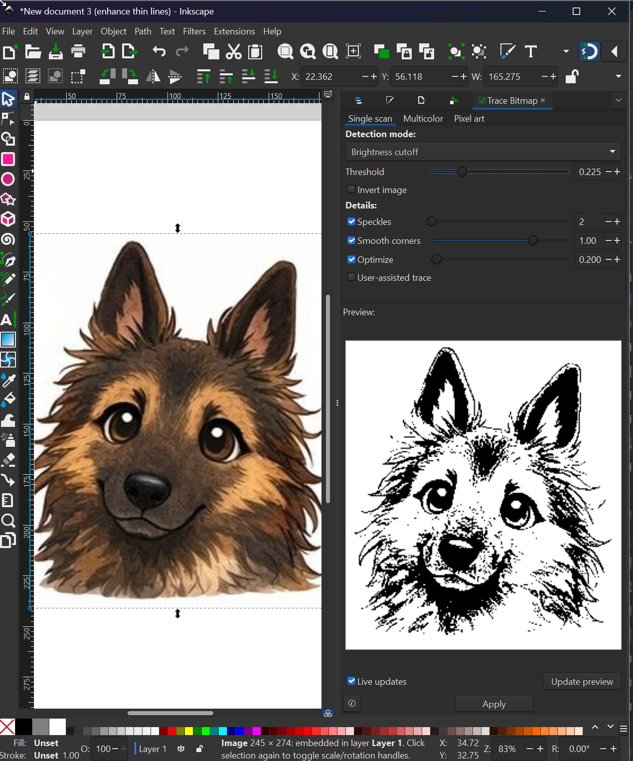
This result is too complicated to cut by Vinyl Cutter with too delicate lines around the picture.
Draw emphasizing line at nose part for Vinyl cutting.
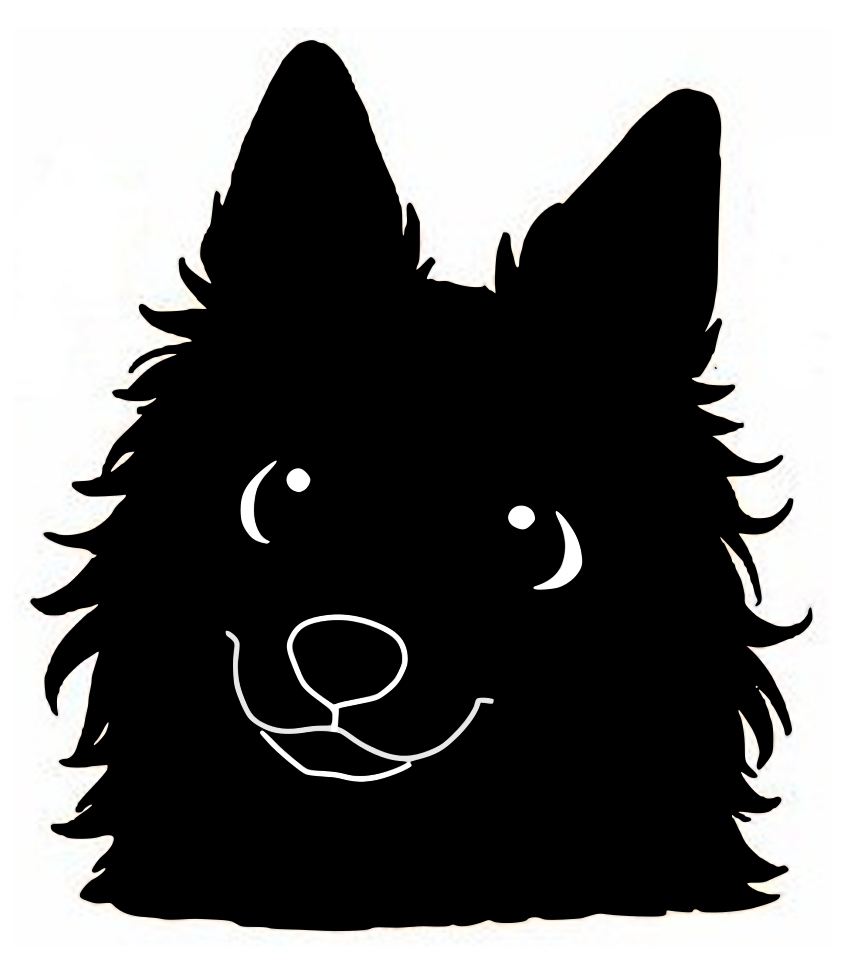
Modifying the “Threshold” level as 0.852 in BitMap menu, got following Mono tone picture on the right side.
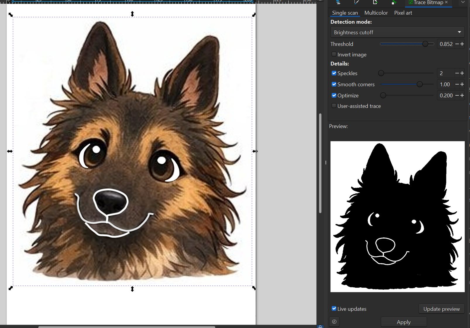
Data for Vinyl cutting
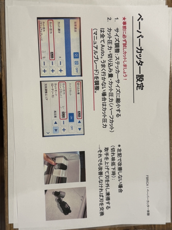
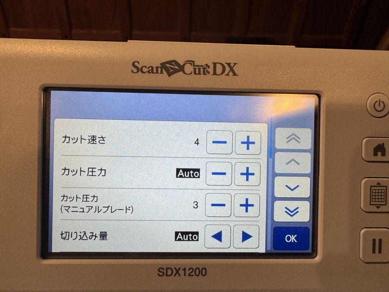
Setting of Vinyl Cutter
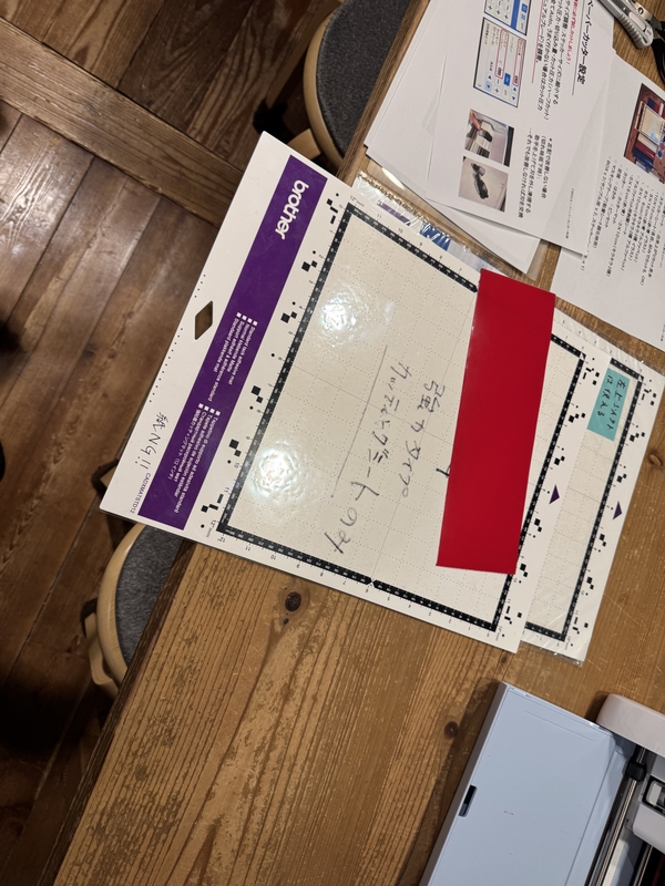
Support sheet to place Vinyl object for cutting
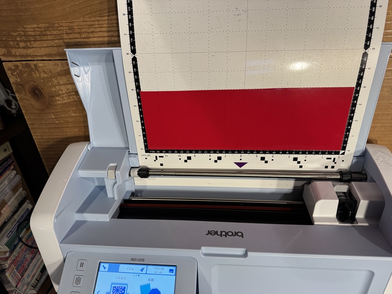
Set Sheet with Vinyl into the Vinyl Cutter.
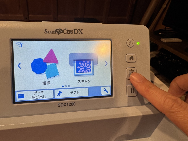
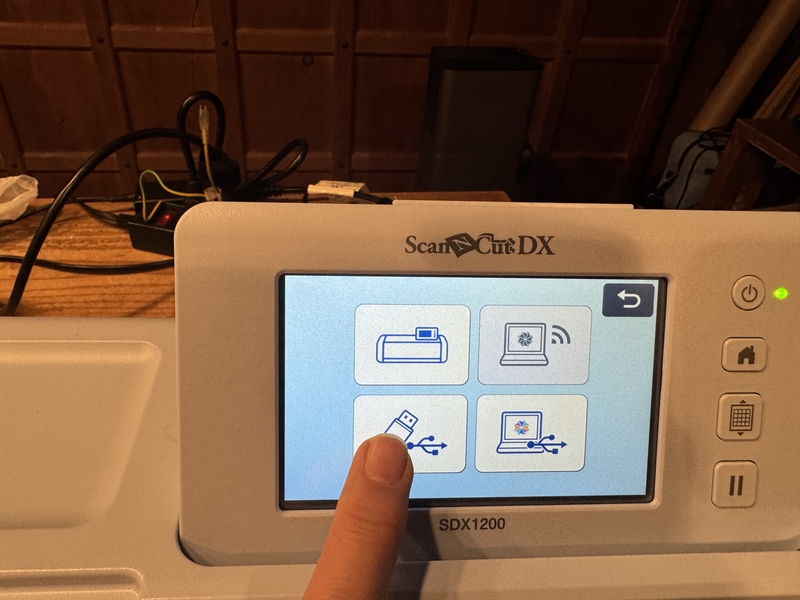
Select Menu
Press Data input by USB port button.
Find Data file in USB port.
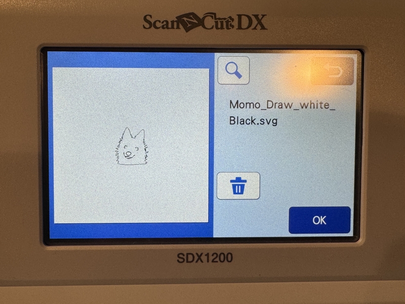
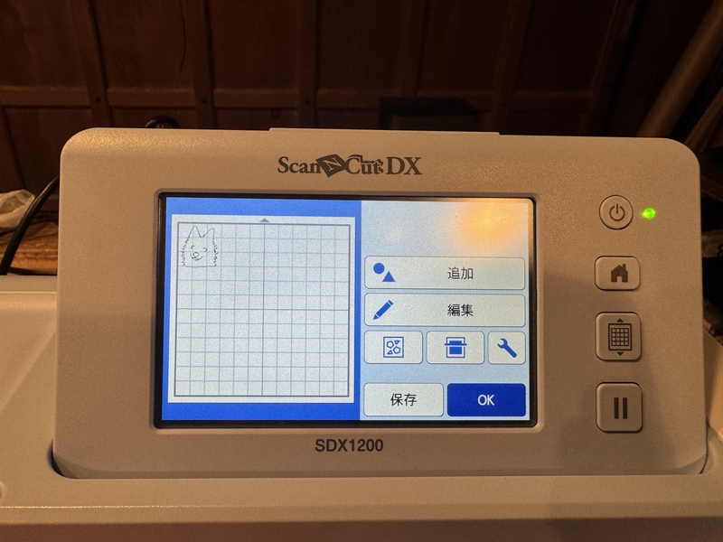
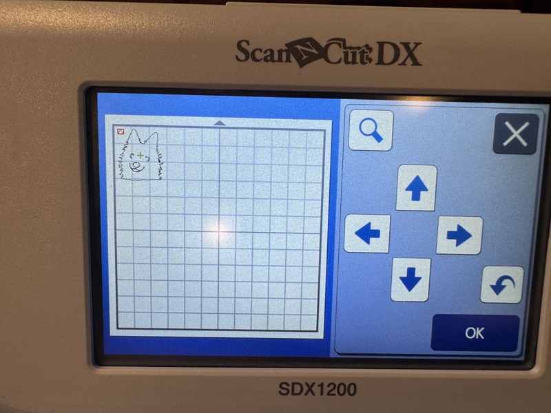
Place drawing at the cutting area, and press “OK”.
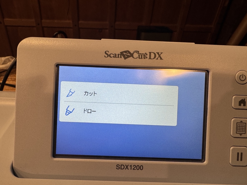
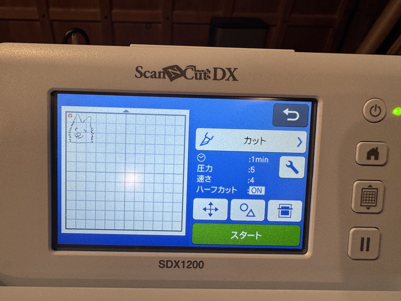
Select “Cut”.
Confirm Cutting condition.
Confirm the cutting position.
Start Cutting.
Cut result came off.
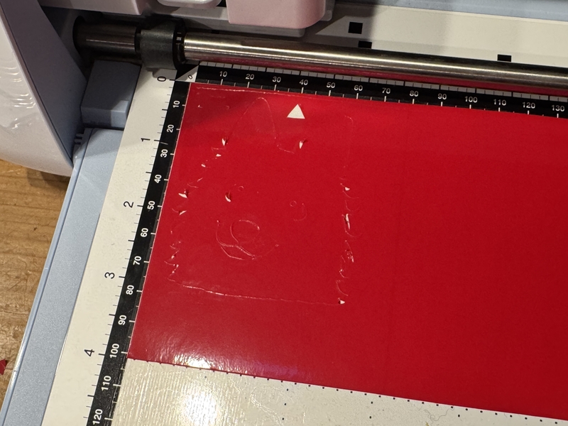
Vinyl cut result
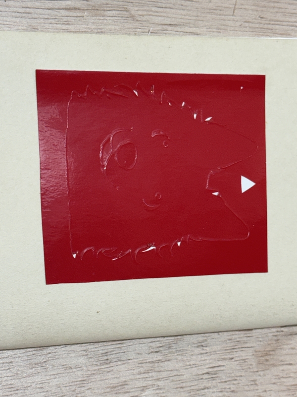
Momo Vinyl Cut result
Files
Bottom Foot Back (Illustrator)
Bottom Foot Others (Illustrator)