13. Molding &Casting
Links introduced in the class
Example of Molding and Casting
This Week’s Assignment
- Group assignment:
- Review the safety data sheets for each of your molding and casting materials
- Make and compare test casts with each of them
-
Compare printing vs milling molds
-
Individual assignment:
- Design a mold around the process you’ll be using, produce it with a smooth surface finish that does not show the production process toolpath, and use it to cast parts.
–> Group Assignment
Individual Assignment
Designing
For Mold & Cast work, I was considering about designing a Logo like emblem for my Final Project.
Since my Final Project is focusing about Semi-Active Vehicle Seat.
I wanted to make a Logo which indicates communication by body language.
Then, “Dog’s” tail communication came up my mind.
I searched in the Pinterest about Dog’s tail design, and found beautiful tail of fox as follows;
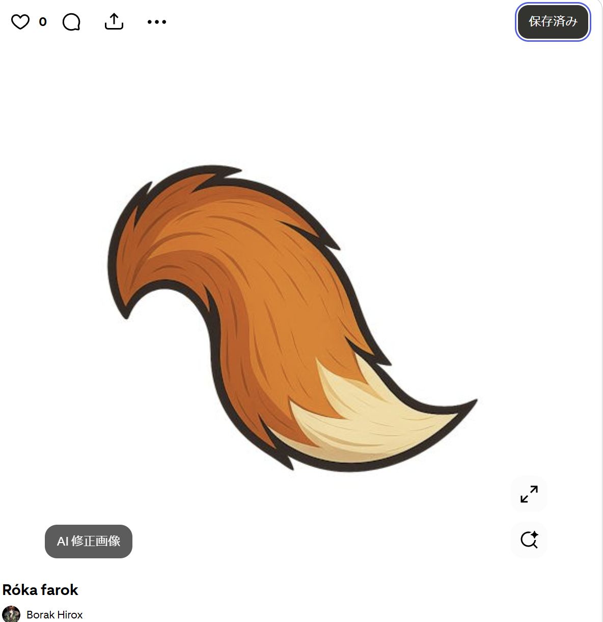
Fox tail design:Róka farok from Pinterest
Imported to InkScape
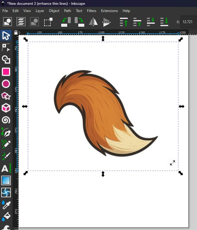
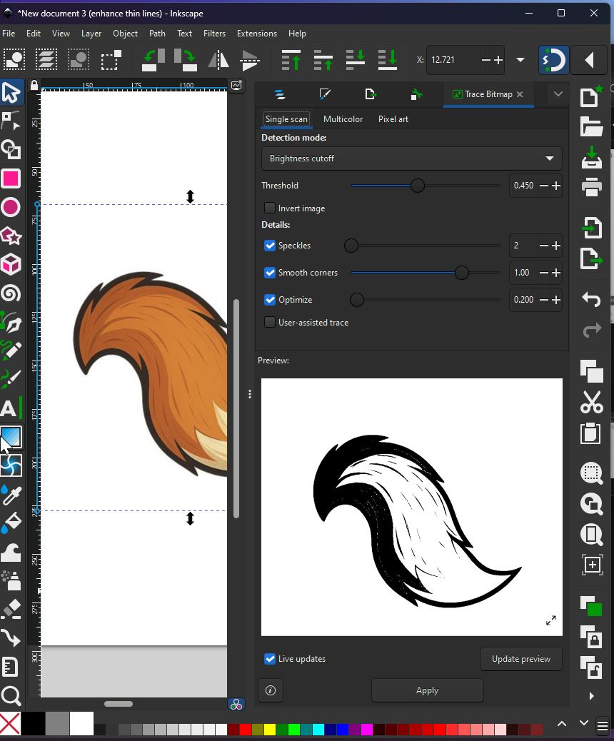
Apply Trace Bitmap
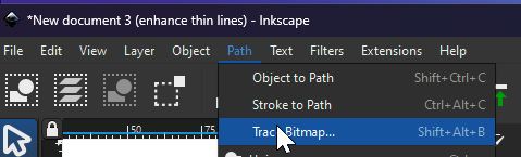
Trace Bitmap applied
Changing threshold to to meet your expectation
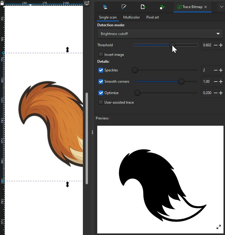
Simple Black and White tail for Fusion design work was made.

Preparation for exporting to Fusion with InkScape
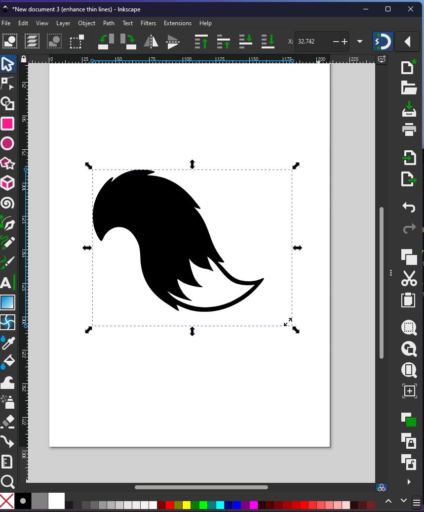
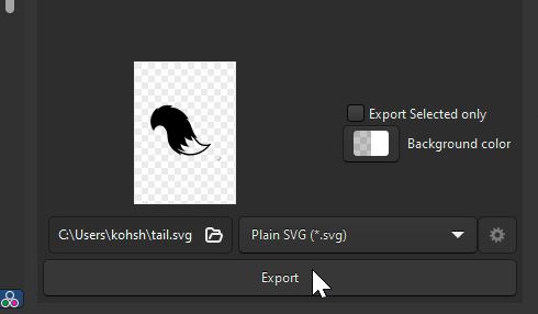
Exporting the file as a Plain SVG file.
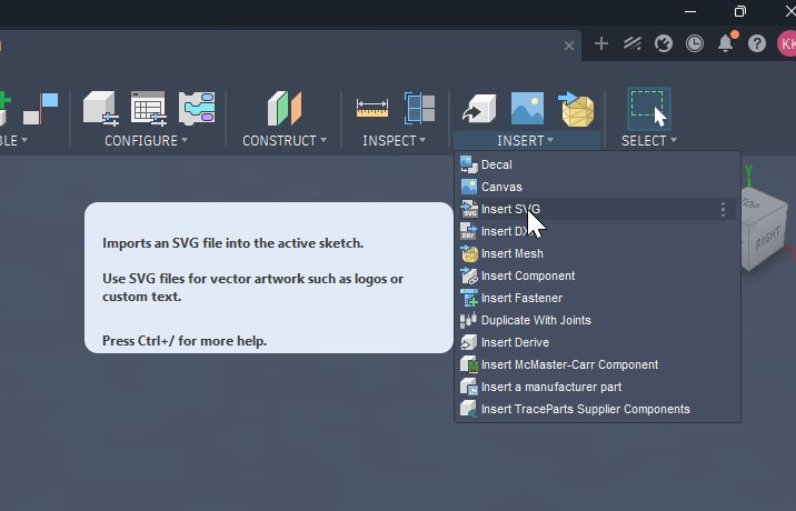
Use “Insert” function of Fusion to import the SVG file.
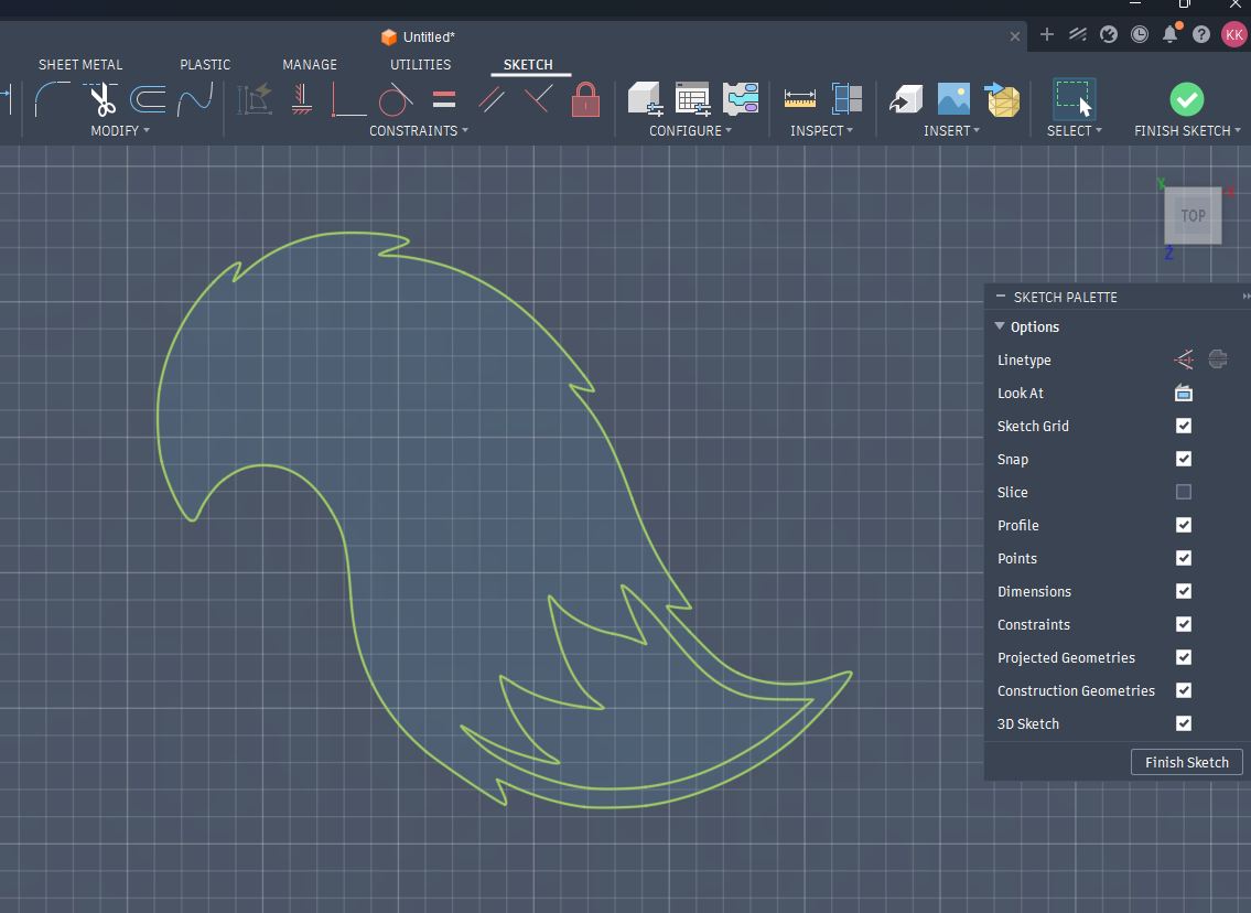
Inserted file in Fusion
Draw circle around the design to make a Cap on the top of motor in my Final Project system.
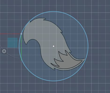
Extruding the inserted Sketch to get Solid object.
Then, make an Offset Plane above the solid surface.
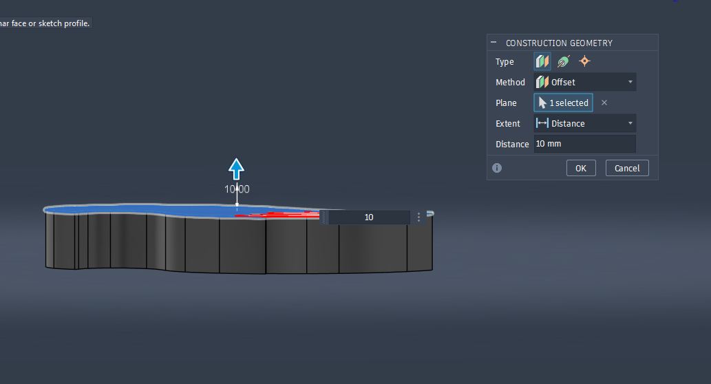
Select “Create Sketch” on the Offset Plane.
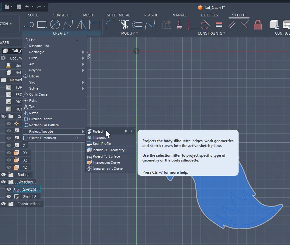
Then, select Project (Create -> Project/include -> Project) in order to get the projection from the Solid surface shape.
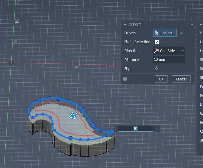
Apply “OffSet” by selecting the projected sketch.
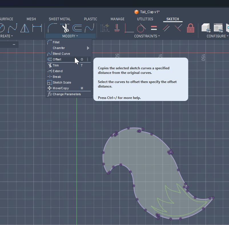
Offset done. In this case 10mm offset towards internal direction was made.
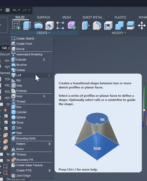
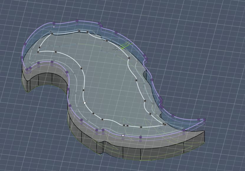
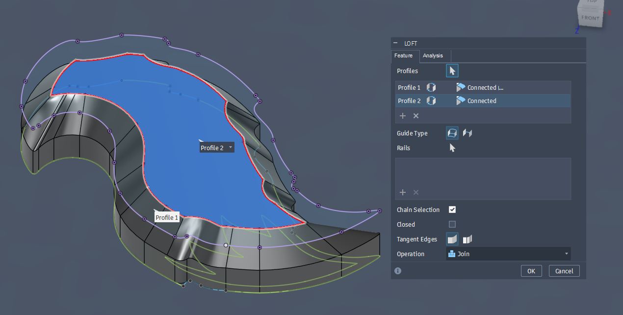
Select Loft Function (Create -> Loft).
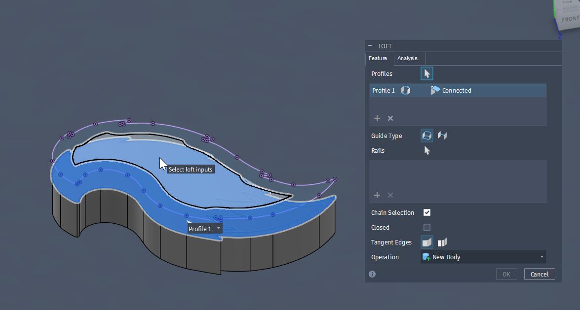
Choose the base layer of the Loft first.
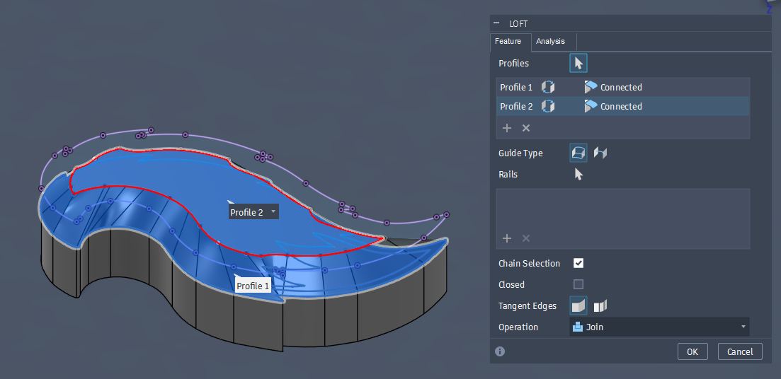
Choose the 2nd layer sketch which was made as an internally offset.
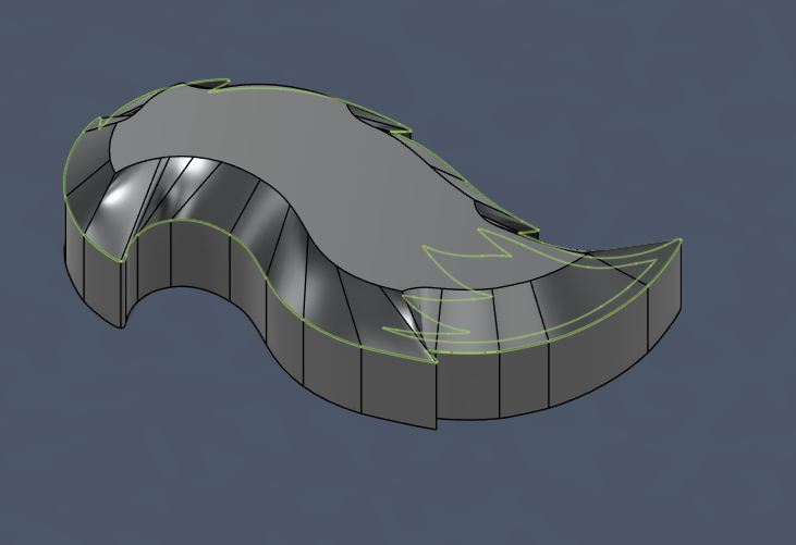
Loft was done.
I tried further smoothing trial by adding one more offset layer farther as a summit layer and add a point in the middle as the summit.
However, it was not completed.
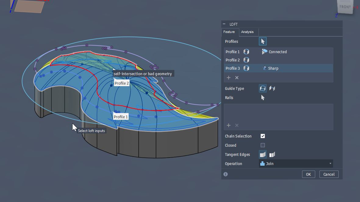
I was instructed that shaper edge than the end mill will make the milling difficult, so that I modified the sketch with smoother edge.
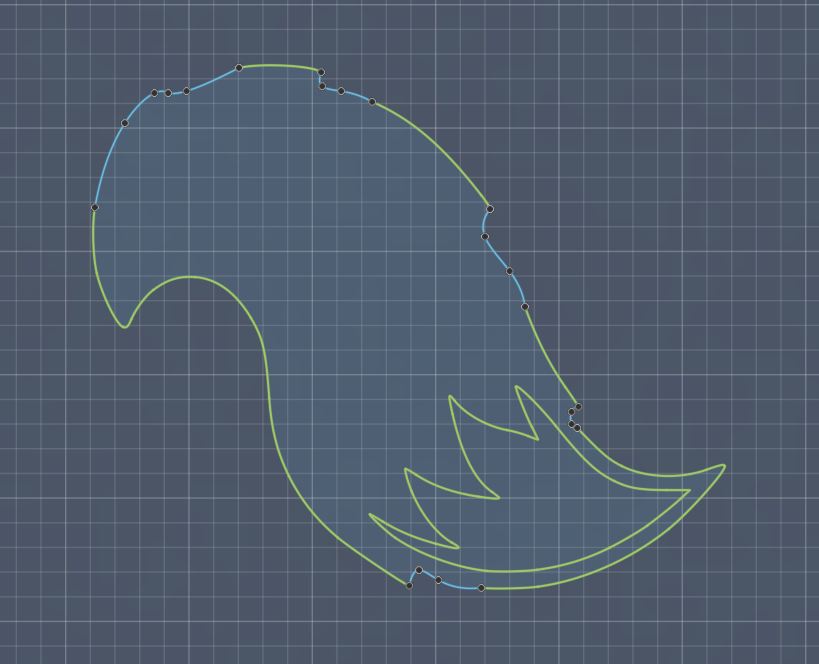
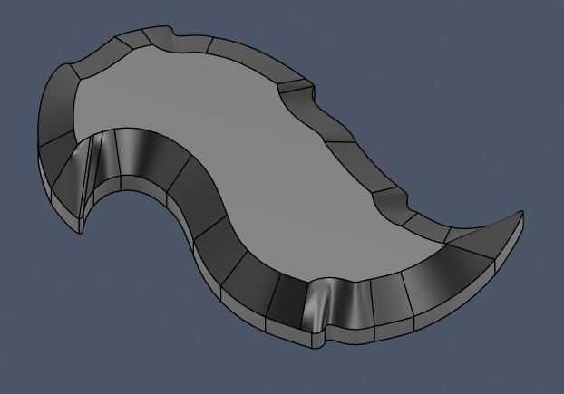
Smoother edged design
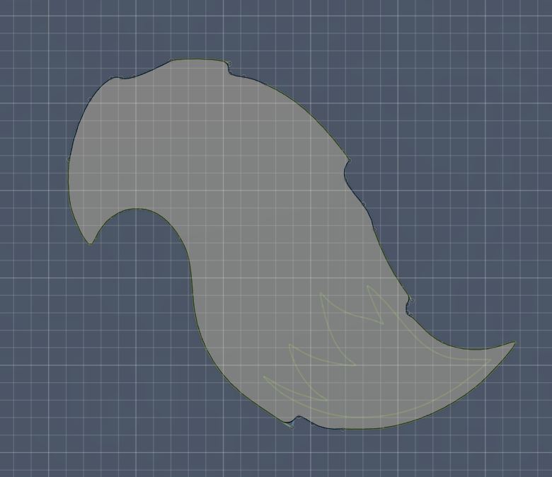
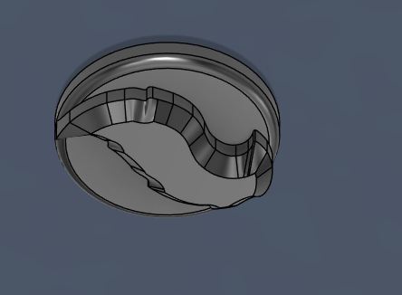
Then, applied loft again.
Lofted result
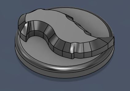
Extruded the circle which I drew at the beginning of Fusion drawing.
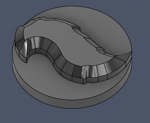
Applied Fillet at the corner.
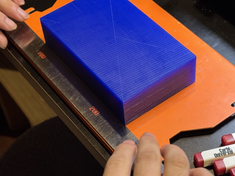
Measured the size of the Wax for Model drawing.
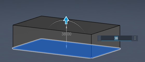
L=148mm, W=88mm, H=38mm
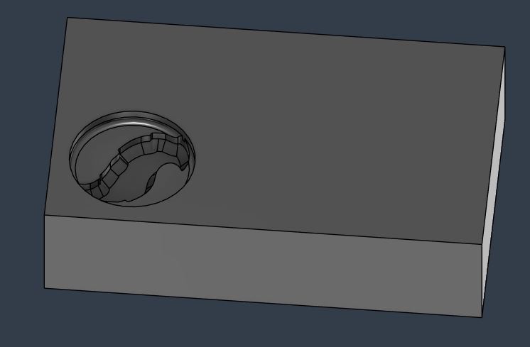
Draw the Sketch of Molding WAX.
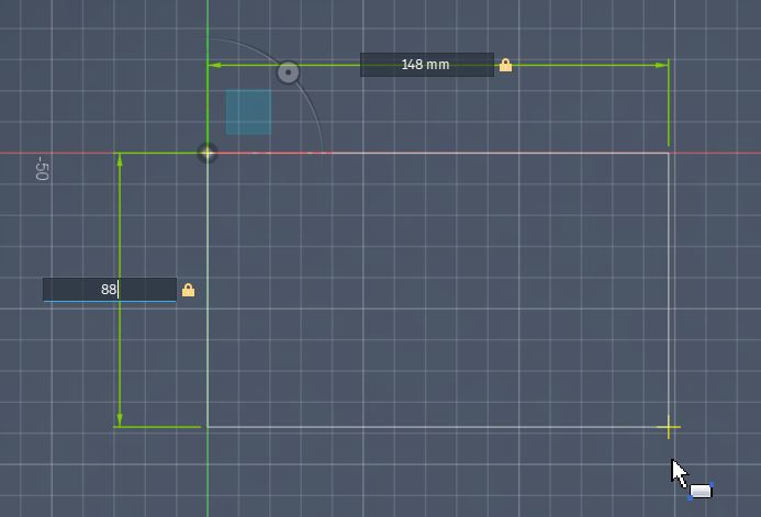
Extruding to make it solid.
Boolean by the fox tail emblem
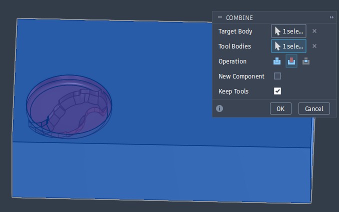
Negative molding was drawn.
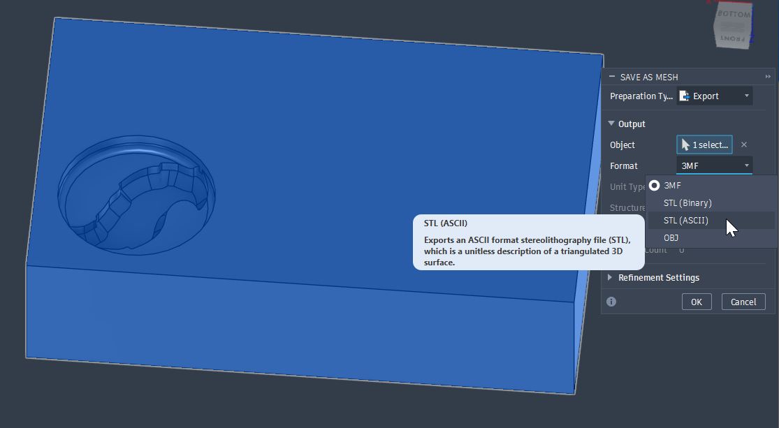
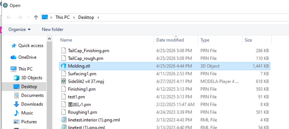
Save the Body as a STL file for SRM milling.
Milling Mold
Preparation for the milling
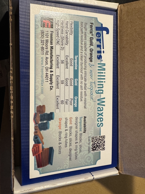
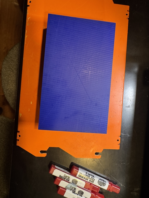
Prepare the Milling Wax.
Selection of End Mill.
In order to mill the molding wax, it is important to choose the end-mill long enough to mill from top to bottom of the Wax.
The below on the left two are the end-mills that I used this time.
The one on the right is normal end-mill for PCB milling.
The diameter of the end-mill is 1/8 inch.
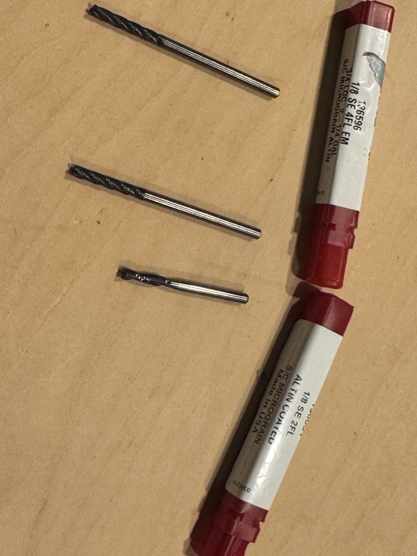
The end-mill length is long enough to reach the total thickness of the wax.
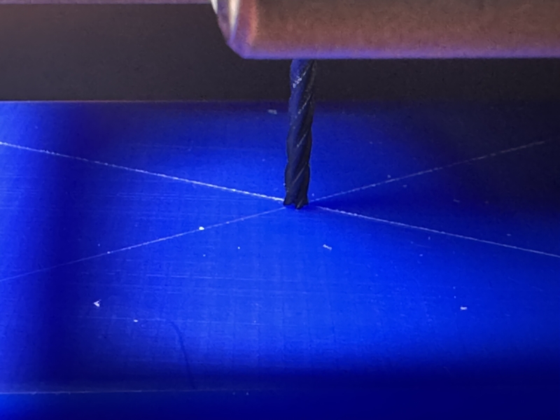
Draw cross lines to point the center as the model center for milling path.
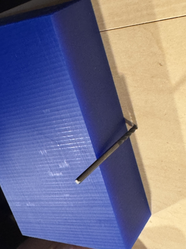
Place the both side tape at the back side of Molding Wax.
Place the wax in parallel to the base line.
Push to stick the wax against the milling base.
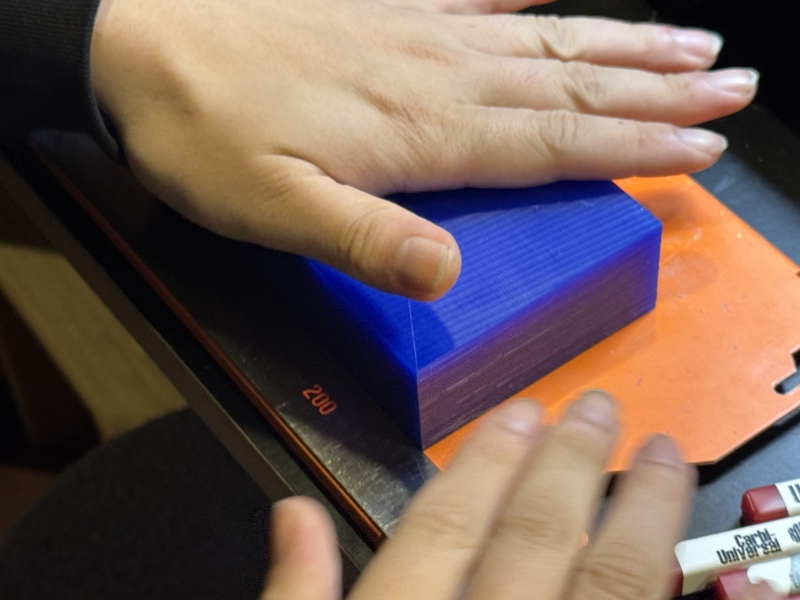
Set the end-mill so that it can reach the bottom of the wax.
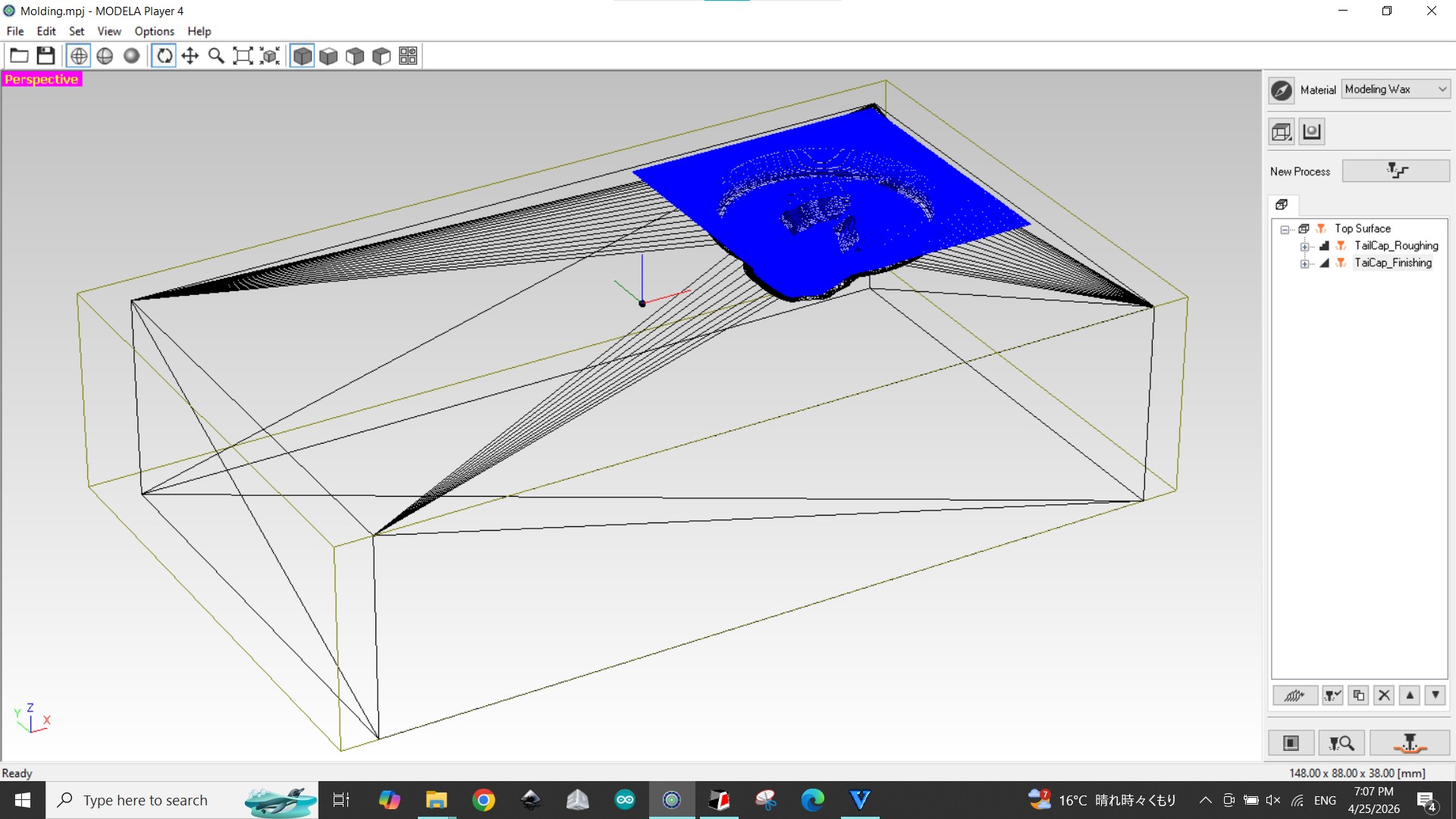
Open Modelaa Player 4 which is the default software for SRM20.
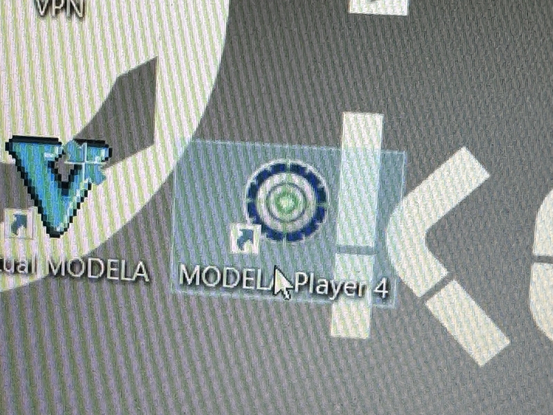
Open STL file from Modelaa Player 4.
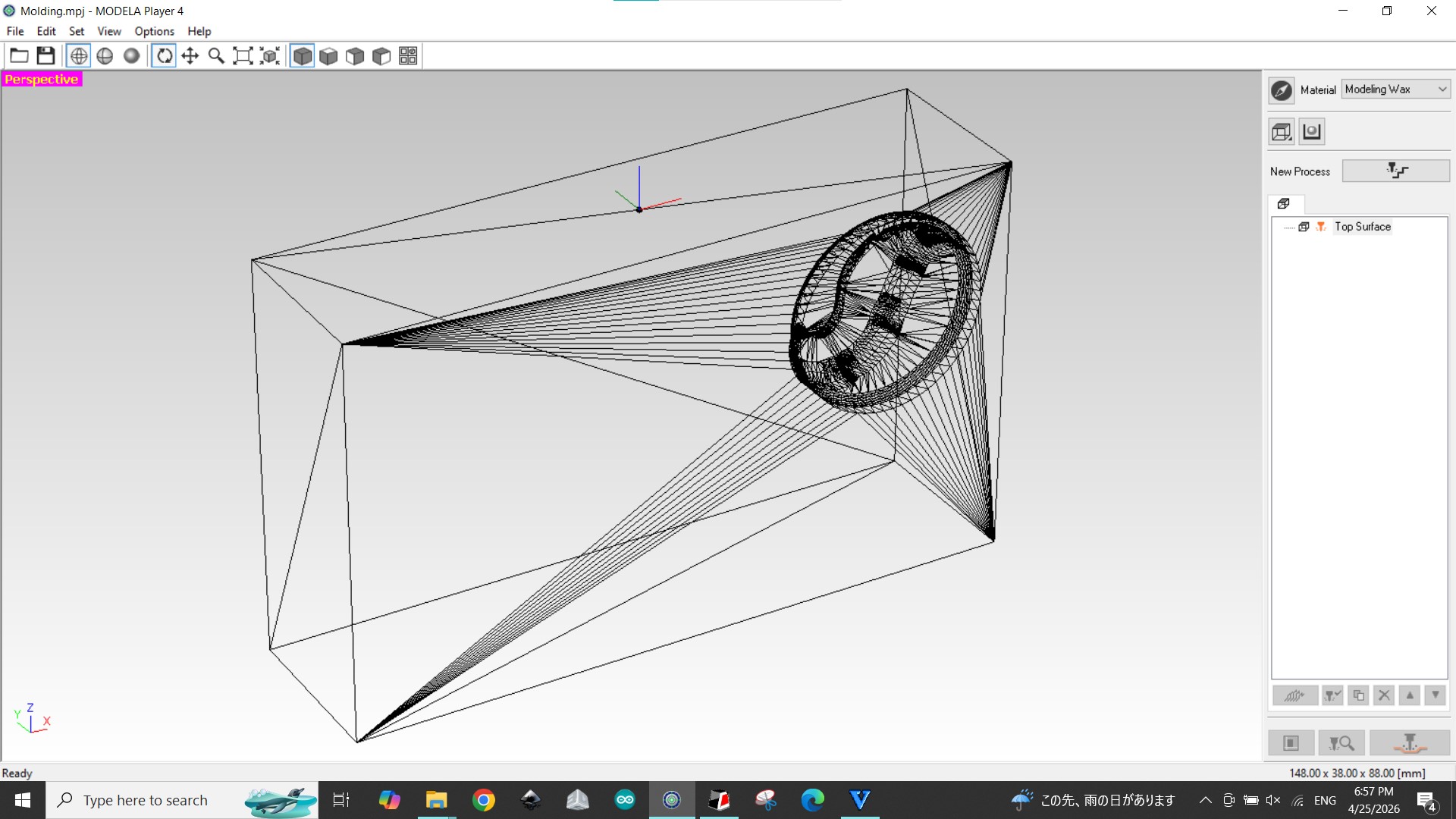
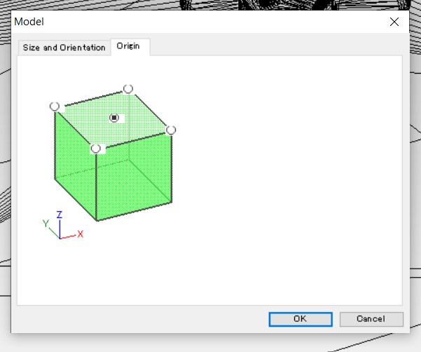
Set Model axis for coordination is not correct.
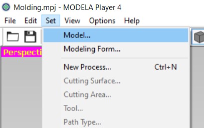
Setting axis.
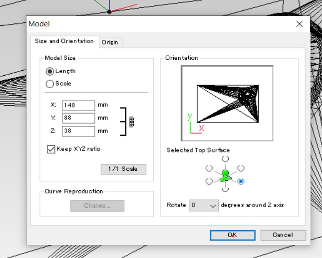
Axis was set correctly.
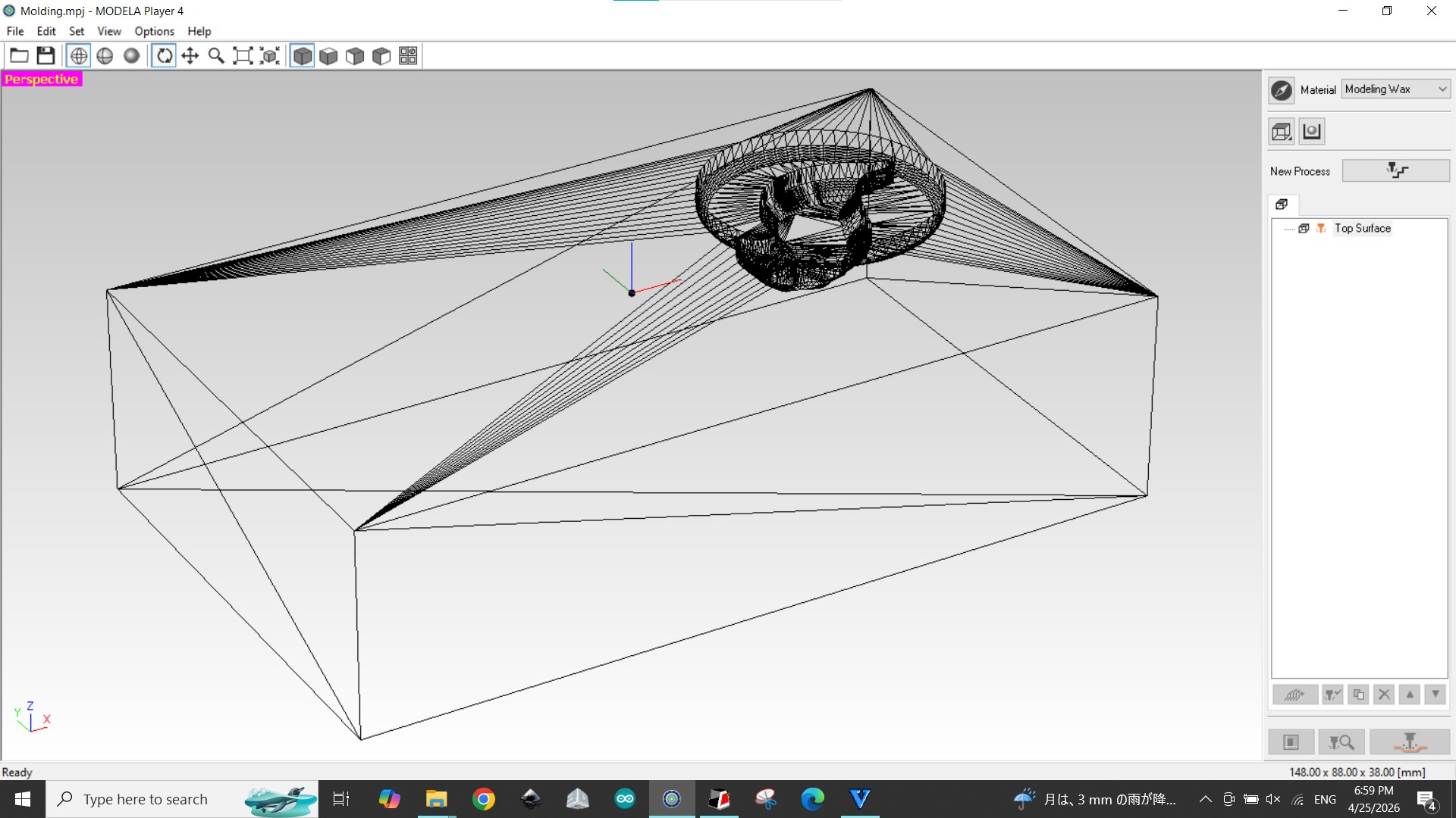
Milling Origin point was set as the center of the model, since it is difficult to manipulate the Mold Wax set at the corner and alignment.
Set end-mill at the center of the Wax on the surface with X-Y position and Z position.
Rough milling
Select Rough Milling menu and Material as Modeling Wax
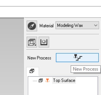
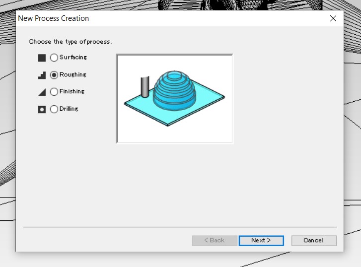
Select “Roughing”
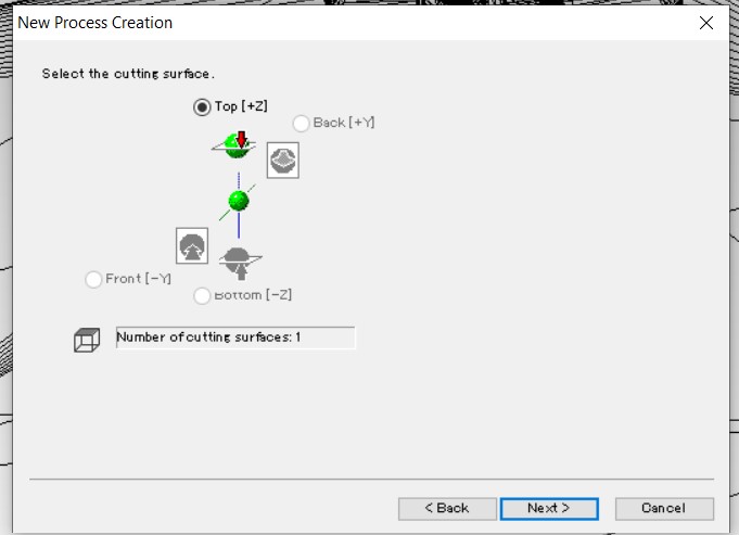
Select the cutting surface
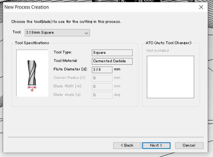
Tool selection
In this case, 3.18mm Square was chosen.
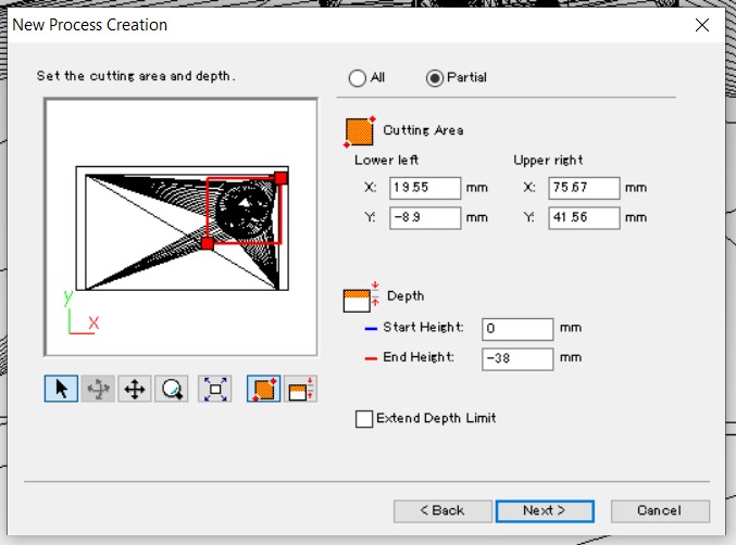
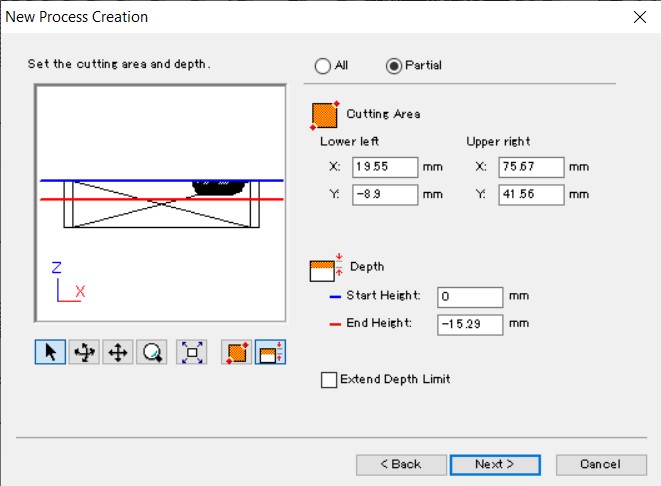
Set the milling area only to minimize the milling time for both X-Y plane and Y-Z plane.
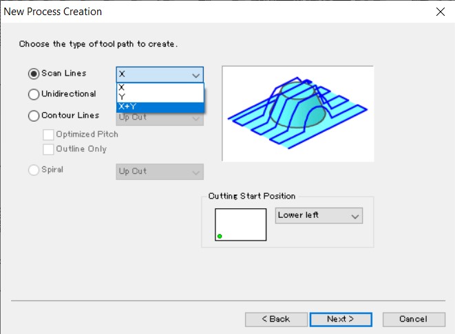
Choose the type of tool path to create.
In this case I set X-Y of Scan lines was chosen.
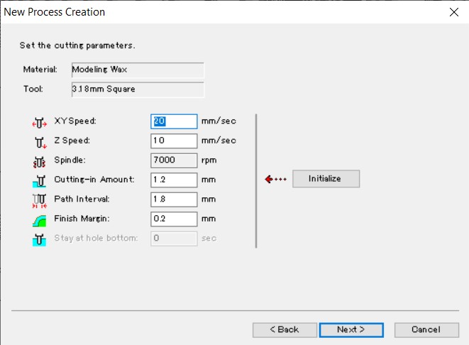
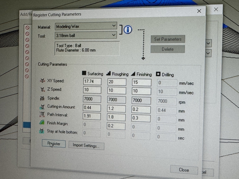
Set the cutting parameters.
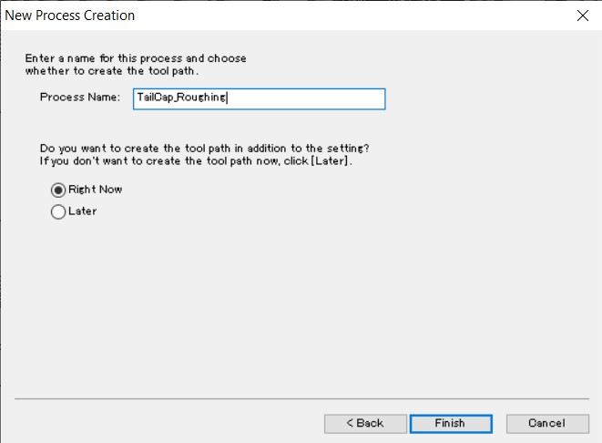
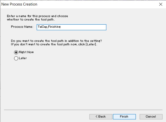
Create the tool path and save the file by naming it.
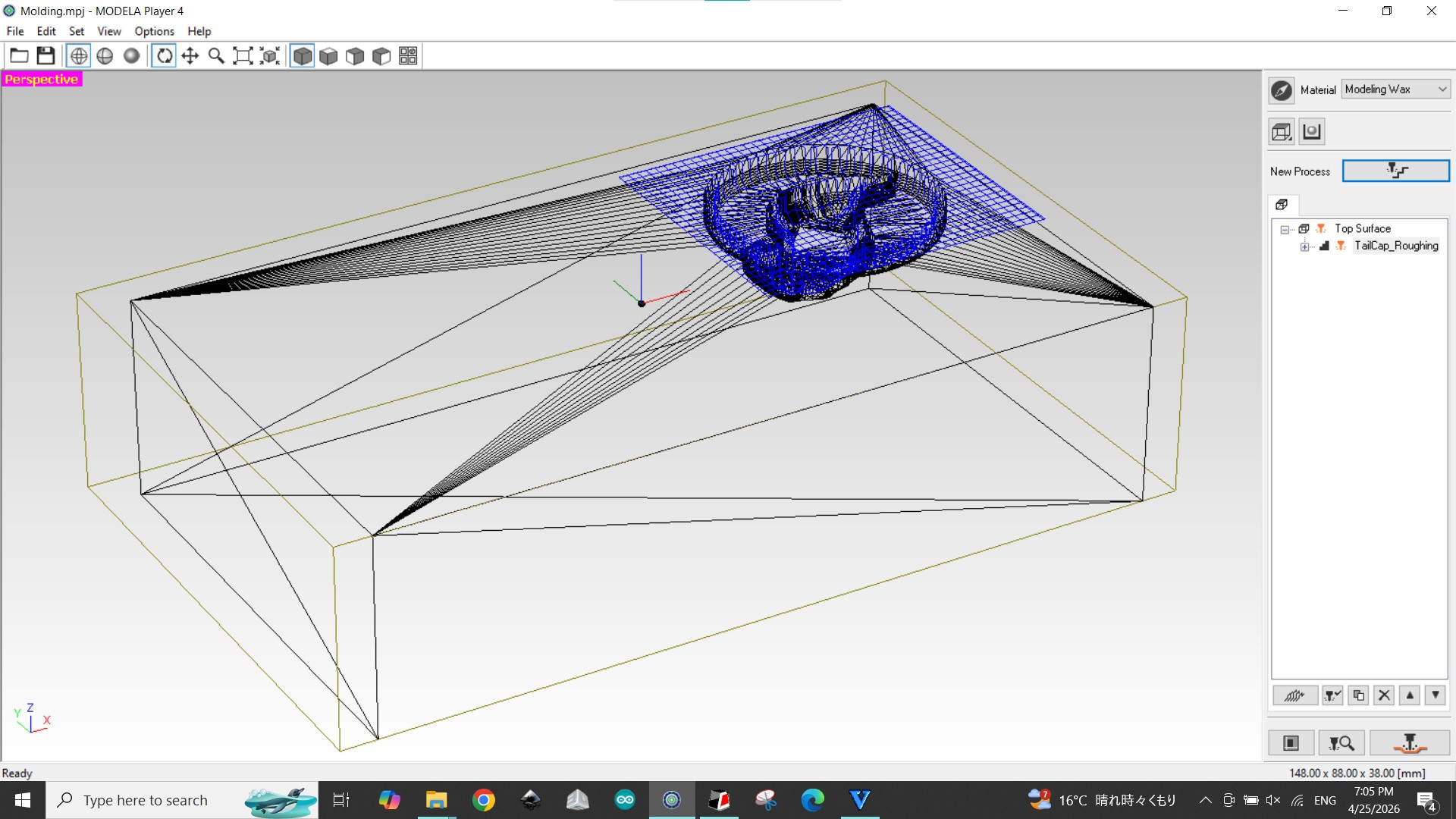
Tool path for Rough Milling was made.
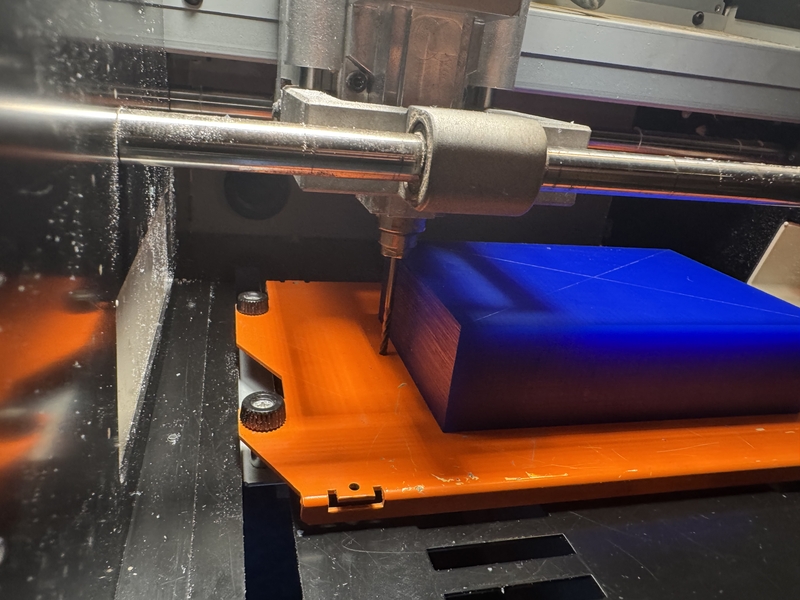
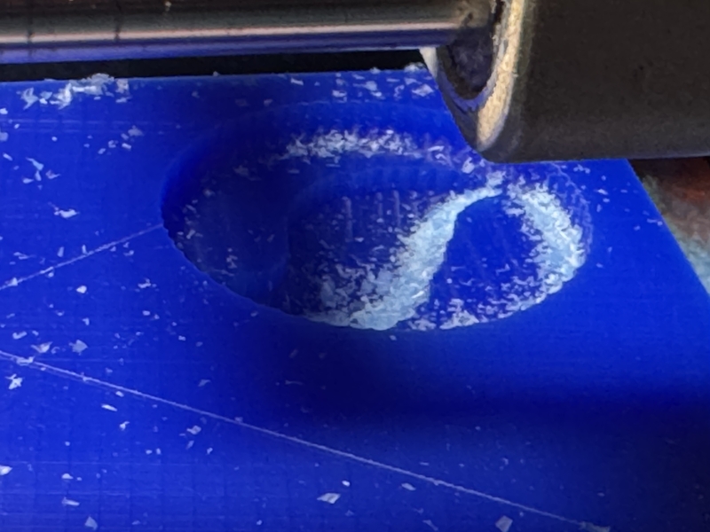
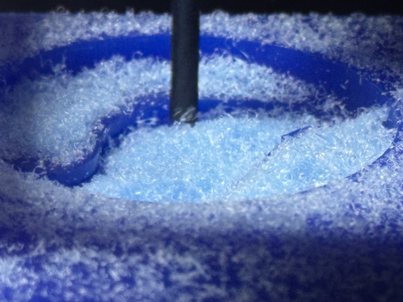
Started rough milling
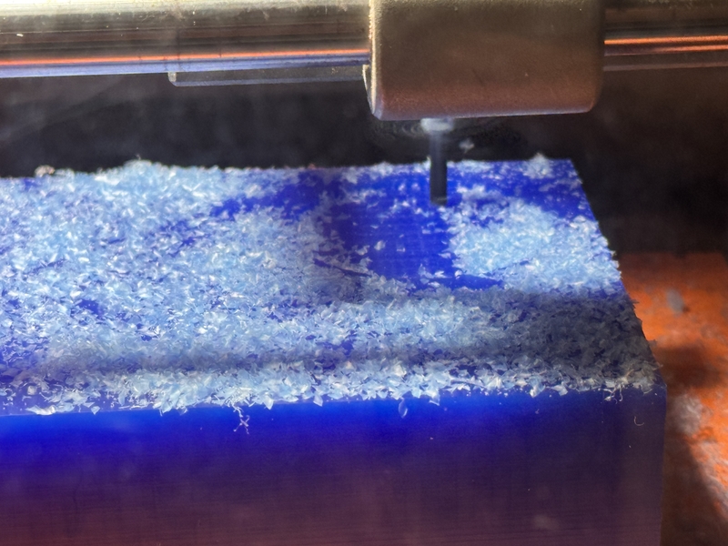
Surface getting covered with milling dust
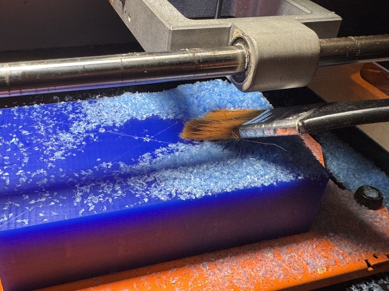
Cleaning the dust by pausing the machine
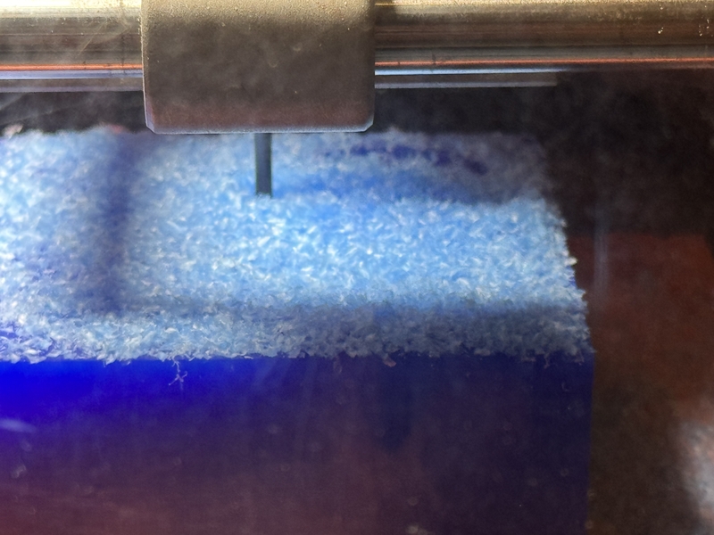
Continue milling
Rough cutting done
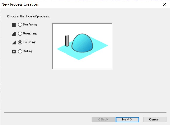
Finish milling
Choose the Finishing type of process.
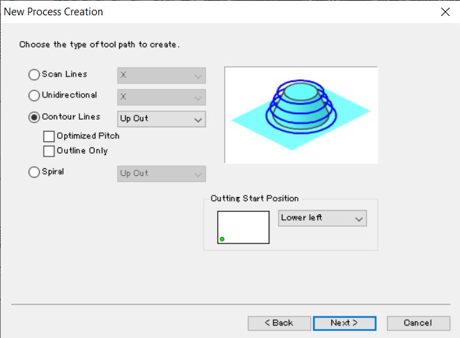
Chose contour type of tool path this time for Finishing.
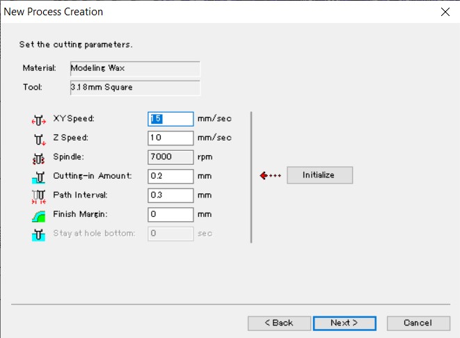
Set the cutting parameters
Create the tool path for finishing and named at the file.
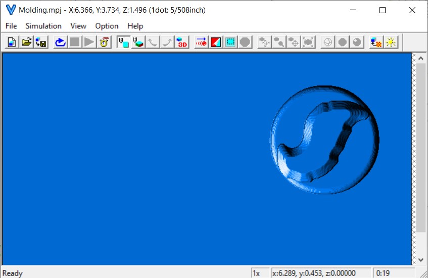
Milling pattern was created as the finishing cut.
Simulation result of finishing milling
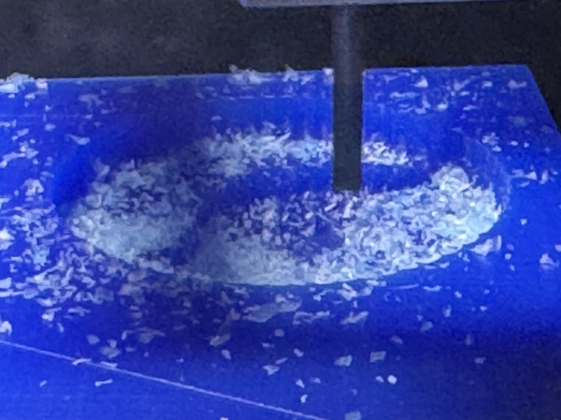
Started finish milling
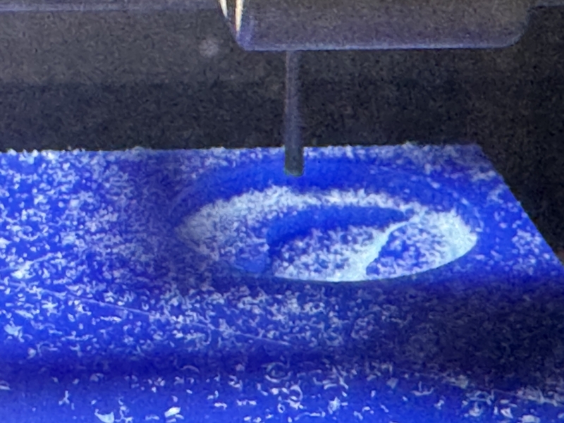
Finishing milling
Milling condition summary
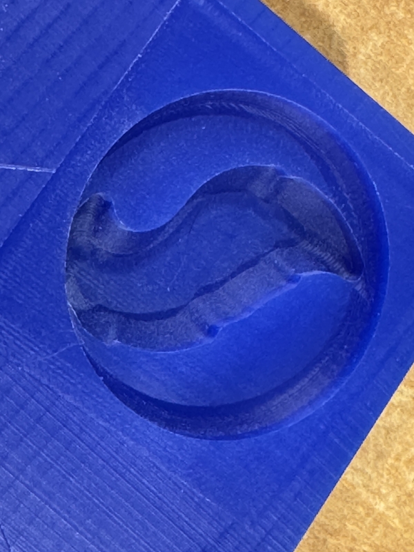
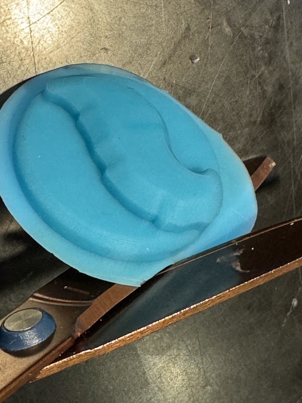
Finish milling result
Casting
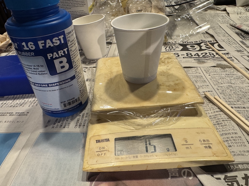
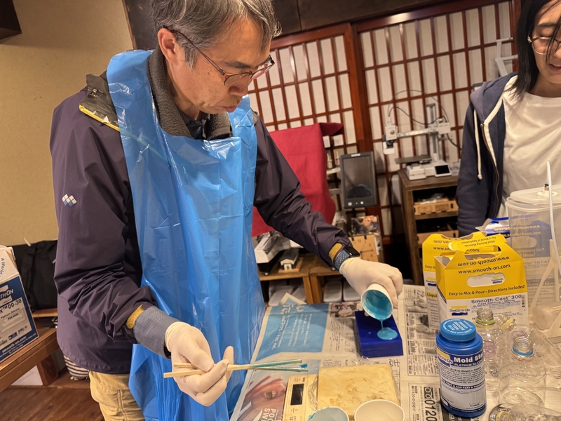
In order to make soft emblem like cover on the surface of motor, I decided to use “Mold Star 16 Fast” as the cast.
Measure 15g of Mold Star 16 A.
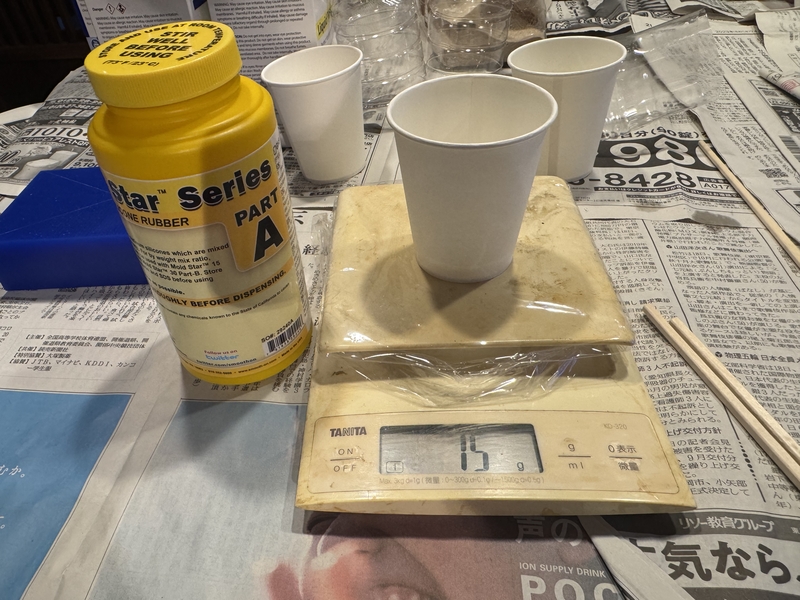
Measure 15g of Mold Star 16 B.
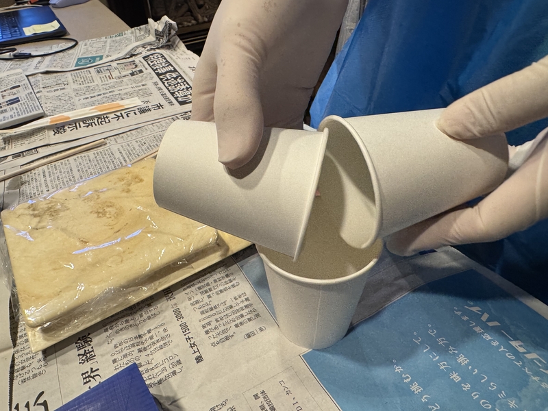
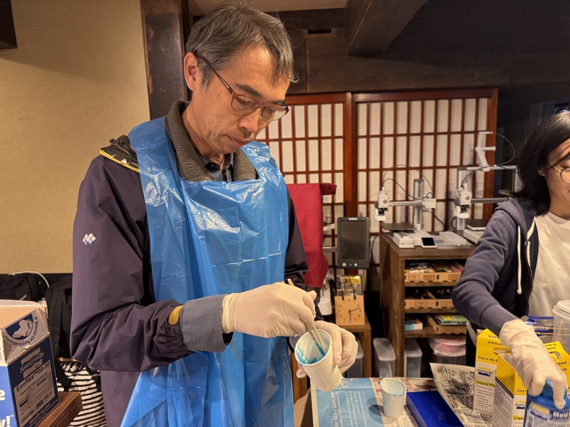
Mixing A and B
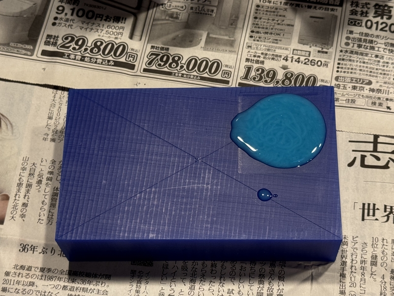
Pouring Mold Star 16 into the mold
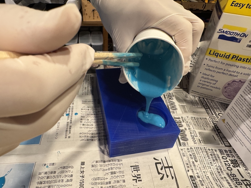
]
Poured all the cast
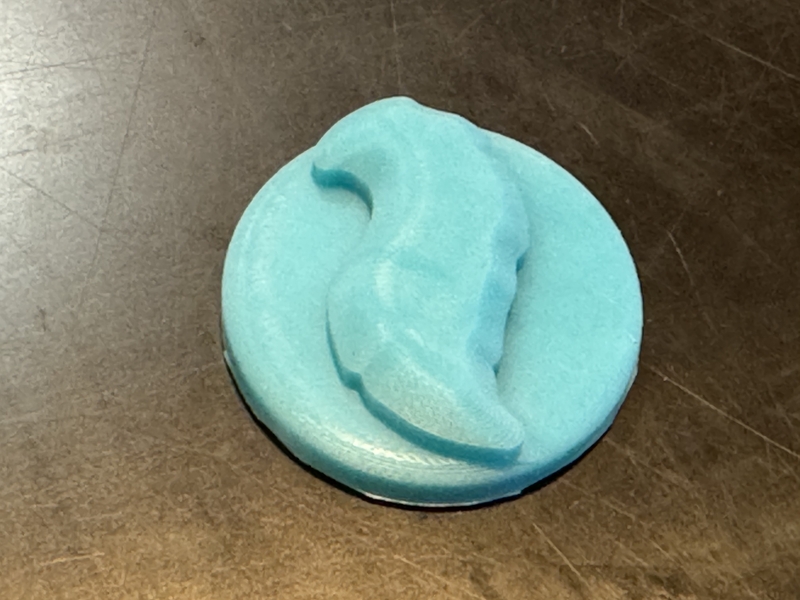
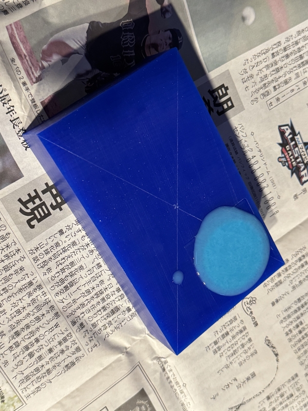
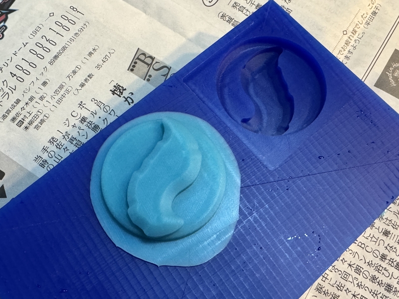
Casted condition next morning
Peeling off the cast
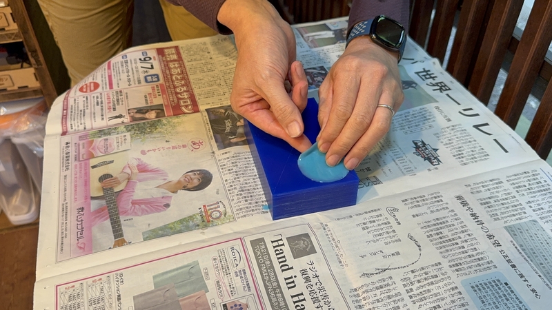
Mold and the Cast
Cutting the edge
Result of Mold and Cast