Magic Table
Final Project Slide
Final Project Video
Click here for my extended cut
Journey
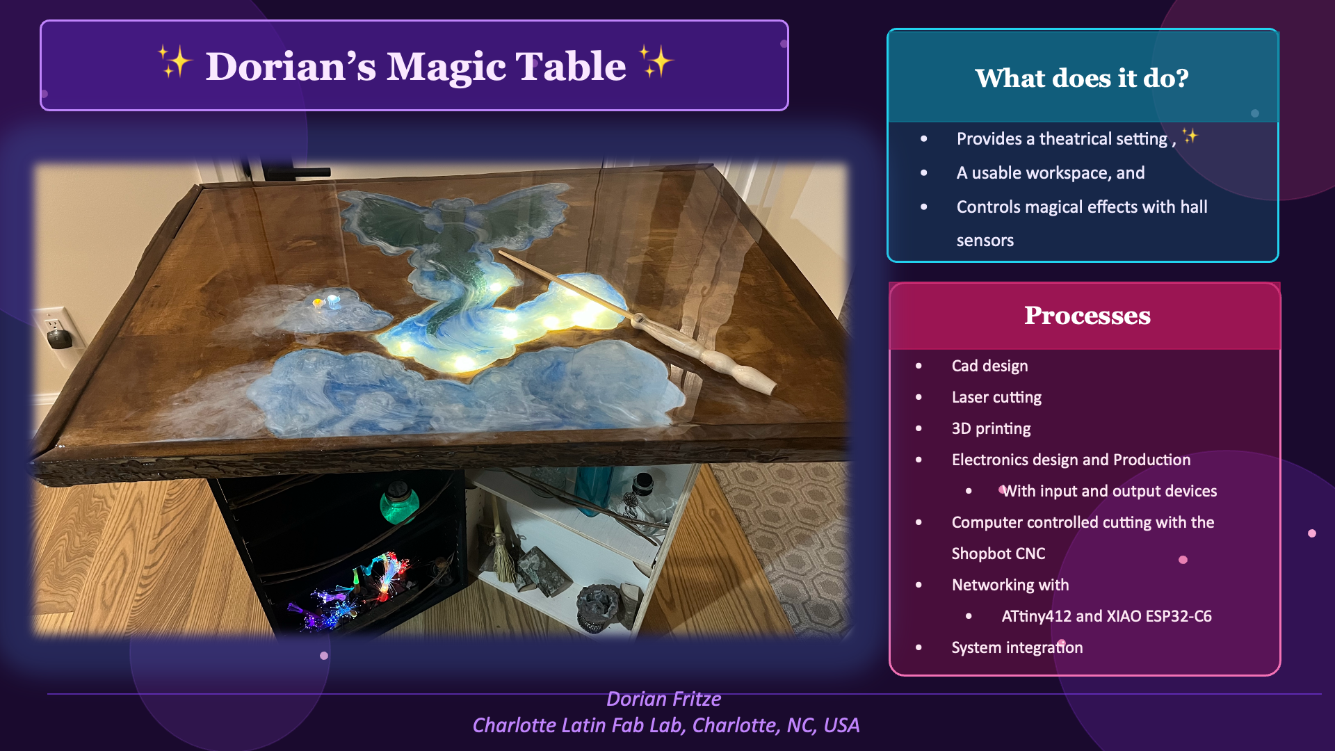
It all started with an idea, a sketch, and a wish list.
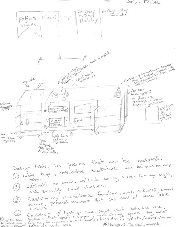
My dream is to create an interactive table for my magical demonstrations. I love to use magic to get people to step out of their comfort zone, ask why, and how? Because once you can understand how, you can explore what if?
Electronics design & Production:
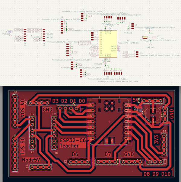
I created 3 PCBs for my magic table top:
- XIAO ESP32-C6 teacher
- facilitates communication
- over WiFi via Telnet
- to the Arduino IDE serial monitor for trouble shooting
- to a user interface through Processing
- through wired I2C communication with ATtiny412 student nodes
- compiles sensor data to run programming based on sequential sensor input
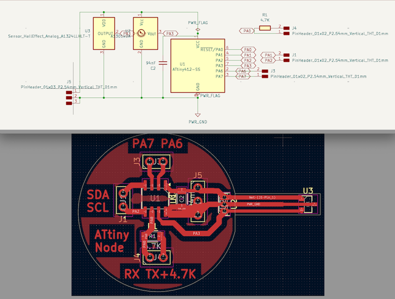
- ATtiny412 student nodes
- reads a sensor
- supports both 3144 digital hall sensors and A1324 analog hall sensors
- can control 1 digital or analog output
- universal code that is adjusted based on the requirements of that node. Address, node type (output type: none, digital, analog), the sensor (digital or analog)
- Switch
- needed for 5V components triggered by a series of sensors that require processing by the ESP32-C6, because the ESP32-C6 only has 3v3 pins
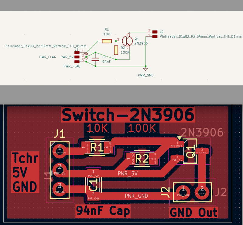
I removed this from my final project, because I used an ATtiny node as the switch. However, should I add a component that has a high current draw like a motor, I will add the switch back in.
Embedded Program & Networking:
Interfacing
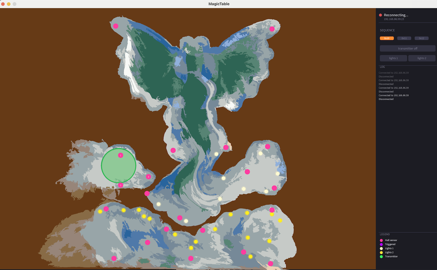
I created a User Interface using Processing UI. Currently it shows where the sensors and lights are located, and has a log. Click here Networking and communications to read more on my user interface.
The files to run my UI are found here: Processing folder
System Integration including Computer Controlled Machining, Laser cutting, and 3D printing
For my documentation on my system integration click here.
In it I go into details on the fabrication of my table top, wire management, and more.
Connecting PCBs and Wire Managment
My electronics were connected using color coded wires.
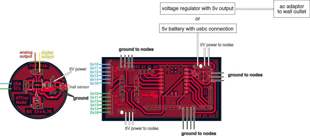
Each ATtiny node has the option for an analog output, red wire; digital output, yellow wire; SDA, blue wire; SCL, green wire; 5V power, white wire; 2 ground connections, black wires, jst connection for programming with RX, yellow wire and Tx, blue wire
0x10, 0x11, 0x12 are the nodes in charge of my Power Spell sequence 1, 2, and 3 respectively. They all had a red led and 1K resistor connected to P7 analog output as a last minute change so that I could see if they were triggered.
0x13 controls the cream colored led string directly surrounding the dragon from its PA7 analog output.
0x14 controls the yellow colored led string directly in the bottom cloud from its PA7 analog output.
0x16 controls the alarm from its PA7 analog output, and the wireless transmitter from its PA6 digital output. (It is the only node to have a special code. It was added at the end of the project as my first spiral. Previously it had just run the wireless transmitter as a regular node.)
0x15, 0x17, and 0x18 will control the red, green, and blue legs of a bunch of RGB LEDs respectively. These LEDs will fill the empty sensor caps until they are needed.
I connected the nodes to the teacher board with the SDA and SCL wires attaching in node number order so that I could easily troubleshoot. (0x15, 0x17 and 0x18 are for a future spiral.)
For wire management, I used cable clamps and 3d printed wire holders that secured the wires more firmly, which helped to hold the nodes in place while keeping the wires secure.
I used JST connections with the RX and TX connections on the ATtiny412 nodes, as well as the power and ground connections.
I would have liked to use them for all connections, but I ran out. The lab had screw terminal blocks, but while they were good for initial prototyping, because you can easily change the wire placement, they kept coming loose!
Future Additions
I would like to make the cabinet base using the files I created in week 7. For my full Week 7 documentation on making these cabinet pieces click here
You can see the cabinet pieces I had made as part of my work station in my final project video.
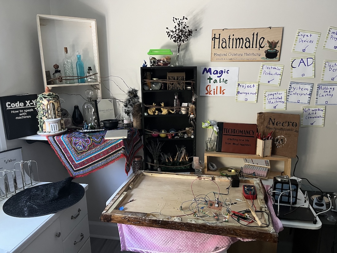
I included as many week's work as I could around my workstation. Flowers and my desk organizer from week 3, 3D printed Ferrgon from week 5, books created for our group machine week video, and wax candles cast in week 14.
Output devices for special effects:
- motors
-
for Fizzbit's tail and / or head
-
speakers
-
musical notes or screeching
-
LEDs -light up magical pathways or other special effects
Input devices so many sensors that could trigger interesting magic:
-
hall effect sensors detect magnetic fields
-
trigger with my magnetic wands
-
have a creature's cage/ box have a magnetic closure to trigger an alarm or monster screeching when opened
-
touch sensors can be used to sense when someone touches different parts of my table, creature enclosures, or potion bottles
-
photo resistor to detect light if a box is opened
-
I would need to use them with a program for reading the difference between readings instead of a threshold. As the daylight changes the ambient light from the windows drastically affects my readings. I would have to change my threshold each magic show depending on the time of day, overcast or sunny conditions, and number of windows in the room. However, if I were to measure the difference in the sensor readings instead, then I could detect a waving hand. This is a rough sketch of my idea as a program. It needs to be fixed, and an output chosen to fit the situation.
 #include <cmath>
 int light_1
 int light_2

 void loop() {
   j = 2
     for(j=>0){
       if(j==1){
         int light_1 = analogRead(PHOTO_PIN);
           if (light_1 => 0 && light_2 => 0);{
             if (abs(light_1 - light_2) => threshold){
               tone(BUZZER_PIN, 1000, 200);  // buzz on with difference in light like hand passing over
             }
           }
       }
       if(j==2){
         int light_2 = analogRead(PHOTO_PIN);
           if (light_2 => 0 && light_2 => 0);{
             if (abs(light_1 - light_2) => threshold){
               tone(BUZZER_PIN, 1000, 200);  // buzz on with difference in light like hand passing over
             }
           }
       }
 }
Bill of Materials
Click here for my full BOM
License
This Magic Table design is licensed under the Creative Commons Attribution-NonCommercial-ShareAlike (CC BY-NC-SA) license, which, "enables reusers to distribute, remix, adapt, and build upon the material in any medium or format for noncommercial purposes only if attribution is given to the creator. If you remix, adapt, or build upon the material, you must use the same license for modified material. CC BY-NC-SA