Interface and Application Programming
link to Fab Academy class links
Group assignment:
- Compare as many tool options as possible
- Document your work to the group work page and reflect on your individual page what you learned
Click here for our group site.
For our group assignment this week we compared different tool options for creating a GUI, Graphical User Interface. I looked into the Arduino IDE serial plotter and monitor. I hadn't realized that Arduino IDE had a serial plotter, but I have used the serial monitor before. I used Claude to help me research. click here for our conversation.
Arduino IDE is a simple, and basic. Great for someone like me who gets easily frustrated when working with programing, since it is within a program that I am already using to run my microprocessors. The downside is that it is visually basic too. So I am torn between wanting a simple program, but wanting it to look pretty too.
Individual assignment:
- Write an application that interfaces a user with an input and/or output device that you made
This week seems to take week11, networking and communications, to the next level. The devices are not just talking to eachother, but to the computer, and directly linked to a Graphical User Interface, GUI. The GUI is accessed through a website that provides controls and/or readouts of the linked devices.
This week expands on our group work for week 11, linked here, where we used espNow to create a webserver, and were able to send the command to turn on or off the led through the website.
three.js research
three.js is an open source JavaScript library that can work across virtual and augmented reality. This video explains the purpose of three.js, and points to where to find more information and support. Is Three.js Worth Learning? by Robot Bobby.
(Click here for threejs.org)https://threejs.org/examples/#webgl_animation_keyframes examples.
User manual for three.js is linked here
Processing.org
Dr. Taylor created a tutorial on Interfacing using Processing, MicroPython, and Thonny IDE. I thought it would be a good place to start.
I downloaded Processing, an open source GUI tool.
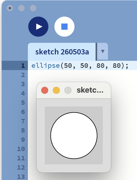
I started with Getting Started by Casey Reas and Ben Fry. First I made a circle:
ellipse(50, 50, 80, 80);
This creates an ellips at the point (50,50), with a height and width of 80.
It is interesting to note that the tutorial says this puts the center 50 from the left, and 50 down from the top. I would have expected it to be up from the bottom left like a typical graph.
The next step in the tutorial was to use this code to create a circle that follows your mouse, and changes to black when clicked.
void setup() {
  size(480, 120);
}

void draw() {
  if (mousePressed) {
    fill(0);
  } else {
    fill(255);
  }
  ellipse(mouseX, mouseY, 80, 80);
}
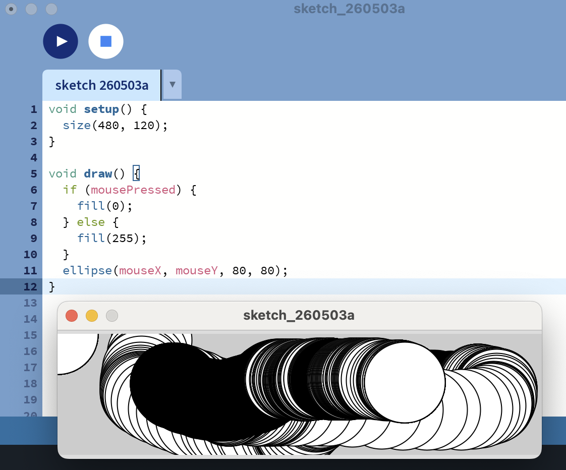
I hadn't realized that this was interfacing before. The mouse is the input. The position is given by the variables (mouseX, mouseY), and the input of the mouse click is given by the variable mousePressed.
These variables must be in the Processing libary, because I didn't create them.
Reading on in the Getting Started page explains how to save and share sketches. It also recomends keeping the Reference page open when coding to use their library of codes and variables. On the reference page I found mousePressed and other premade shortcut codes.
For the Reference page click here
I like that when using an example code I can control + click to pull up a help menu, from which I can choose "Find in Reference." That is very intuative and helpful for a beginner like me!
The site recomends saving my sketches often, and altering the names slightly so that when I break something, I can revert to an older working sketch.
It is like they know me...
Sketches are saved to the "sketchbook" by going through the File menu.
To share sketches use the Export Application in the File menu. It bundles code into a single folder, and creates an application for Windows, Mac or Linux. I am not sure what a self-contained, double-clickable version of my project is, but I assume I will find out shortly as that is what the Export Application makes.
Note that the application folders are written over each time you Export Application, so move your exported folder.
I watched some Processing tutorials on their website processing.org/tutorials
Starting with Hello Processing
Canvas the screen you are creating your image in. The grid origin is in the top left where positive x moves to the right, and positive y moves down.
Code Editor a place where you put code
toggle ruler turns the rulers on and off in the canvas
I made a rectangle.
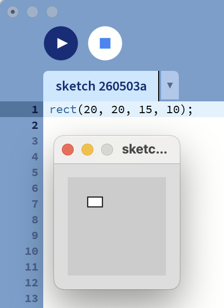
I tried to make it larger like the example, but my canvas is too small.
To change the size of the canvas the code is size(x,y); Set this up in void setup() as explained in the 4th lesson "Interact" of the Hello "Processing!" tutorial.
I created a surprized face using ellipse and rectangles, because I figured the code would be surprized that I created it.
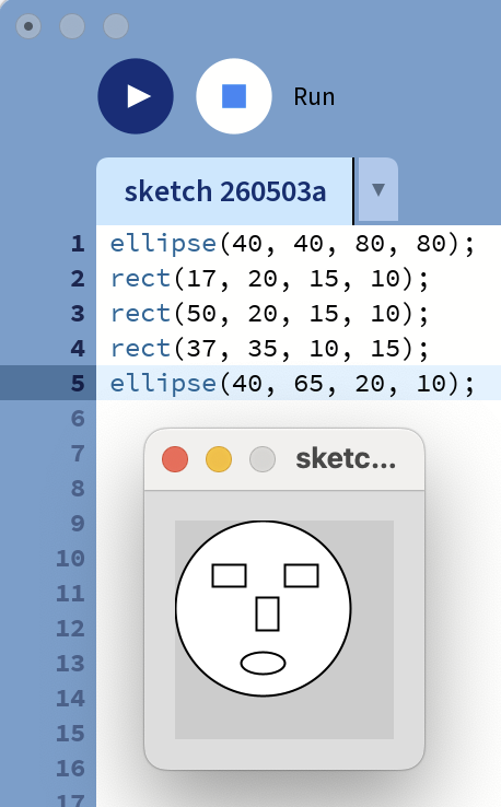
It is important to write the code in display order. The objects are filled with white so they will cover eachother.
To color the shapes:
stroke pen color stroke(R,G,B) or stroke(grayscale) fill fill of color fill(R,G,B) or fill(grayscale) background color of background
With RGB colors 0 is no color, and 255 is the maximum. With grayscale 0 is black, 255 is white.
call functions stroke() and fill() before your shape all objects created after the stroke() and fill() functions will be the called colors
The colors use light color blending not a paint color blending.
background(0,220,220);
fill(240,210,210);
ellipse(40, 40, 80, 80);
stroke(0,220,220);
fill(100,0,200);
rect(17, 20, 15, 10);
rect(50, 20, 15, 10);
fill(220,200,200);
stroke(100);
rect(37, 35, 10, 15);
fill(50);
ellipse(40, 65, 20, 10);
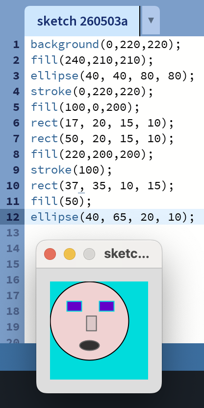
I made the background bluegreen, gave it cool purple glasses, made the face peach, and nose slightly darker, used gray to outline the nose and mouth, and fill the mouth.
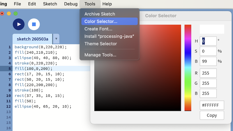
I tried to access the Color Picker tool by clicking on my color functions, but the help menu didn't have Color Picker in its options. I did find this page, Color, by Daniel Shiffman on selecting color. Click here for Color.
This tutorial explained that the color selector is in the Tools menu.
In lesson 4 Interact I learned to set up my canvas in the void setup() section of my program.
void setup() {
    size(500,400)
}
Commands in this section are only run once in the beginning of the program. In this example an ellipse is drawn where the mouse is on the screen. If I wanted to show each output like a brushstroke, I would define my background within the void setup() section. That way it does not redraw the background each time a cirle is made.
I first changed the code for the ellipse to move with the mouse.
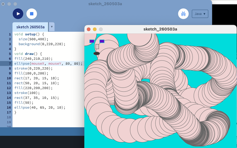
The face did not move with the ellipse. To fix this I changed all x to be mouseX+(40-x), and y to be mouseY+(40-y), since the original placement of the ellipse was (40,40)
Oops, my face was upside down. I altered my formula to add (40-x) and (40-y) instead.
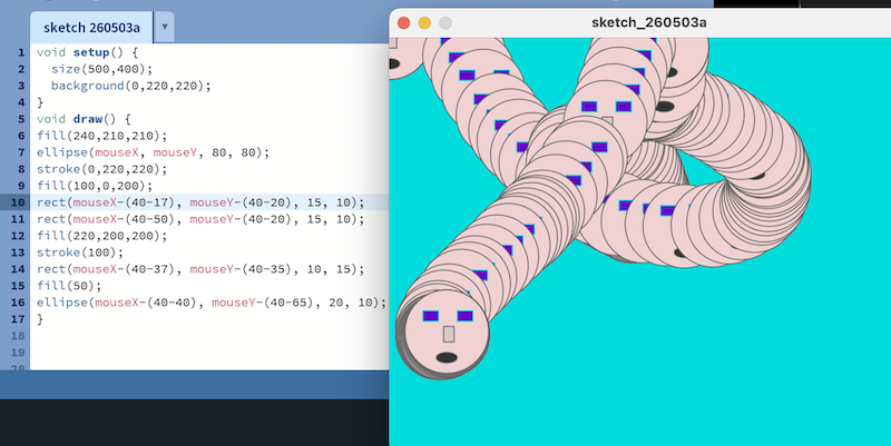
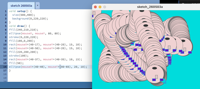
This worked, and my final code was:
void setup() {
  size(500,400);
  background(0,220,220);
}
void draw() {
fill(240,210,210);
ellipse(mouseX, mouseY, 80, 80);
stroke(0,220,220);
fill(100,0,200);
rect(mouseX-(40-17), mouseY-(40-20), 15, 10);
rect(mouseX-(40-50), mouseY-(40-20), 15, 10);
fill(220,200,200);
stroke(100);
rect(mouseX-(40-37), mouseY-(40-35), 10, 15);
fill(50);
ellipse(mouseX-(40-40), mouseY-(40-65), 20, 10);
}
In Dr. Taylor's tutorial, he used Thonny IDE to interface with Processing. I was hoping I could use Arduino IDE instead, since I have been using it. I asked Claude if that was possible. Yes I can use Arduino IDE, so I will try to use it now. For my conversation with Claude click here.
Also in that file, you will see my work with Claude to create my program that uses hall sensors to move a light from node to node. It will also be able to be controlled through a GUI using Processing, which interfaces with Arduino IDE.
When I used this code to determine the addresses of the nodes I received 3 very different responses.
#include <WiFi.h>
void setup() { Serial.begin(115200); WiFi.mode(WIFI_STA); Serial.println(WiFi.macAddress()); }
void loop() {}
Node 2: I2C Slave 2 ready at address 0x09 B4:3A:45:89:F2:B4
Node 3 (Teacher) Hello from Seeed Studio XIAO ESP32-C6 58:E6:C5:1A:7F:28
Claude said the "I2C Slave 2 ready at address 0x09" is from old I2C "garbage," likely from my networking week, and will go away when I upload the new program. I wonder why Claude didn't say anything about the responce form Node 3? It is the first time I have used this microprocessor. Could be a normal firt time message? It will likely go away with the new program too.
The first 3 bytes of the addresses show that the chips are all made by Espressif, and the first 2 were from the same batch.
After working out, and uploading the programs, I had trouble connecting.
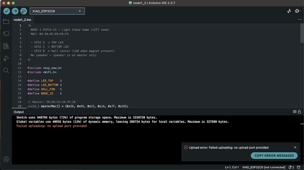
After trying all the regular fixes of unplugging and replugging, and pressing boot then reset and releasing reset then boot, I showed Claude the error. Claude said the Arduino IDE may have lost track with all the unplugging, and to Tools -> Port to make sure my
java /dev/cu.usbmodem101is selected.
That had been my problem!
I keep messing up pinouts! Why are they so confusing!
I now have my pins correct. On nodes, D2 is the top led, and D6 the bottom. D1 is the sensor.
D6 the bottom, and D7 top on the master with D1 the sensor.
The working files are linked below:
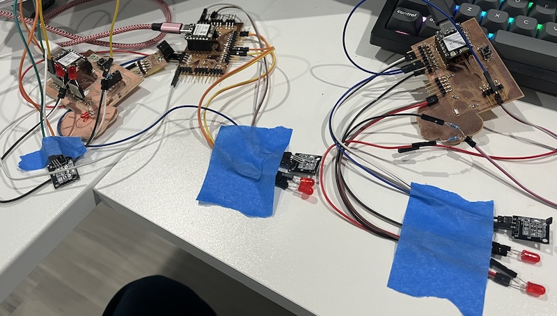
This video shows the lights being controlled by the arrow keys and the mouse. The hall sensors are triggered by the magnet in my wand. Should I not move the light or trigger a hall sensor in 10 seconds it.
This program is not perfect, but I am able to see how the inputs and outputs are effecting eachother and the Processing program. It is very cool to see!