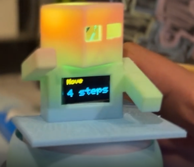
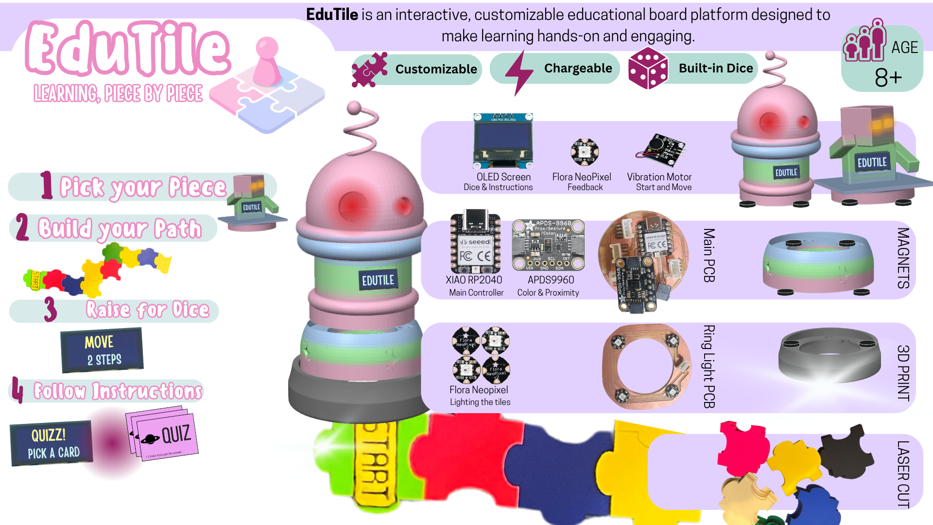
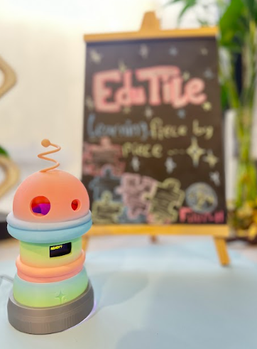
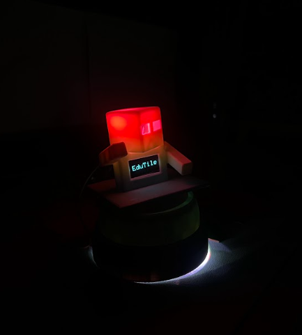
EduTile is an interactive, smart board game that transforms learning into a hands-on adventure. Players move across educator-designed tiles using a smart playing piece — a character embedded with a screen, sensors, and vibration feedback.
Unlock Learning Through Play with EduTile
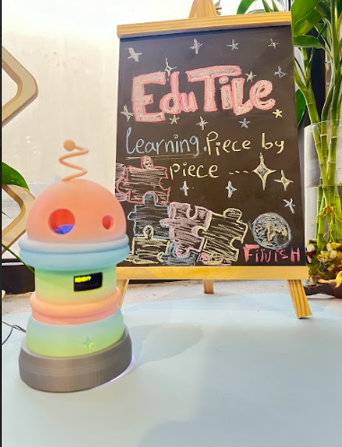
EduTile; Learning piece by piece
Set your pieces, Build your path, and let's go
EduTile is an interactive, smart board game that transforms learning into a hands-on adventure. Players move across educator-designed tiles using a smart playing piece — a character embedded with a screen, sensors, and vibration feedback.
Eduitile comes with ready-to-use themes that you can start with right away:

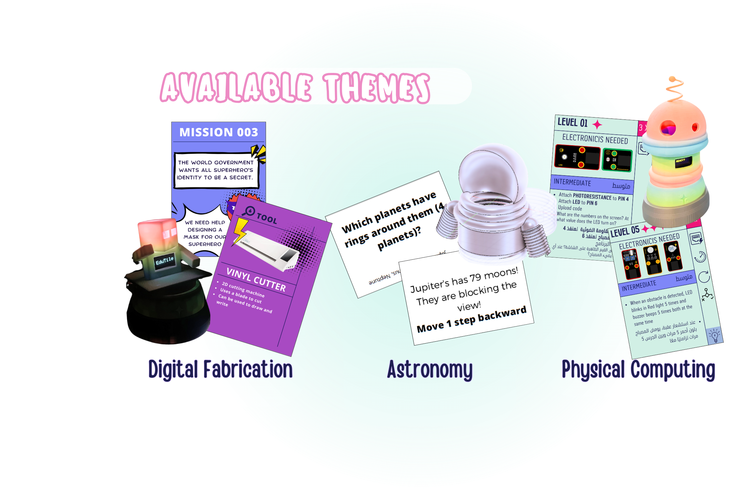
Each theme includes a set of cards and activities designed to introduce learners to these topics in a playful way.
But Eduitile is also fully customizable. As an educator, you can:
Create your own materials and content — for example:
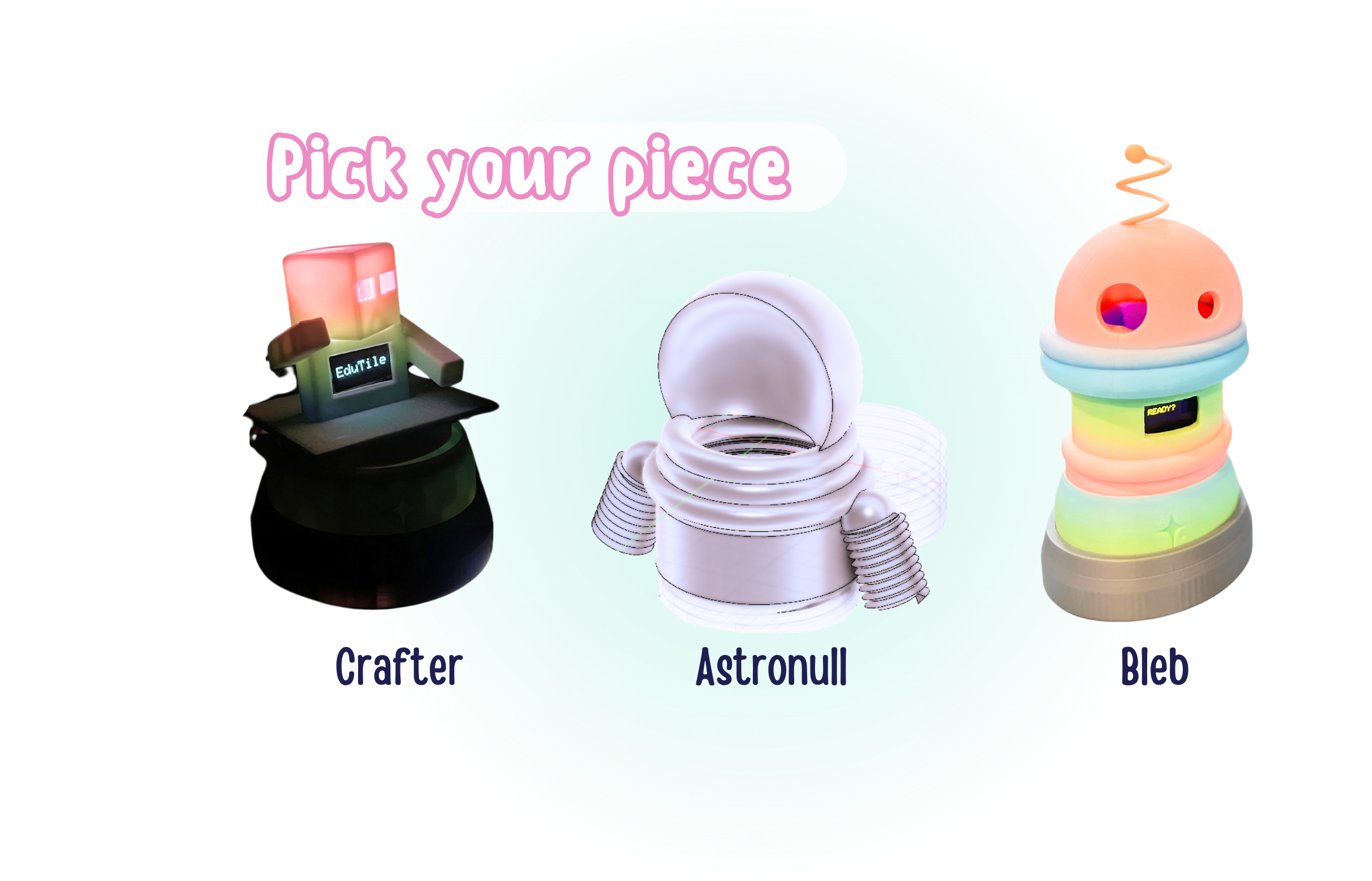
Design and print your own characters to match your subject or classroom theme, making the game more relatable for your learners.
This way, Eduitile becomes a flexible platform — you can use the existing themes or transform it into a tool that perfectly fits your teaching goals.
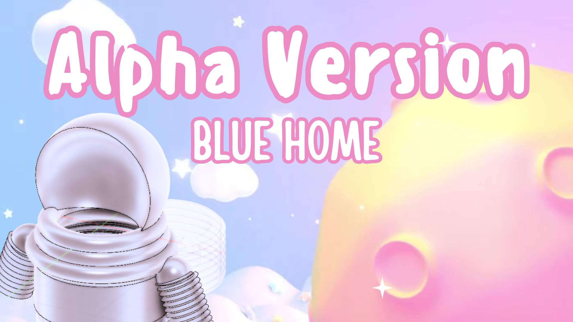
My passion for board games and educating people about the Solar System that we live in drove me to make this board game called Blue Home.

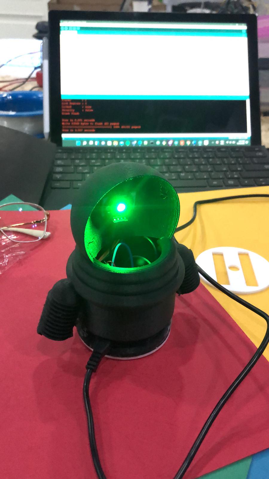
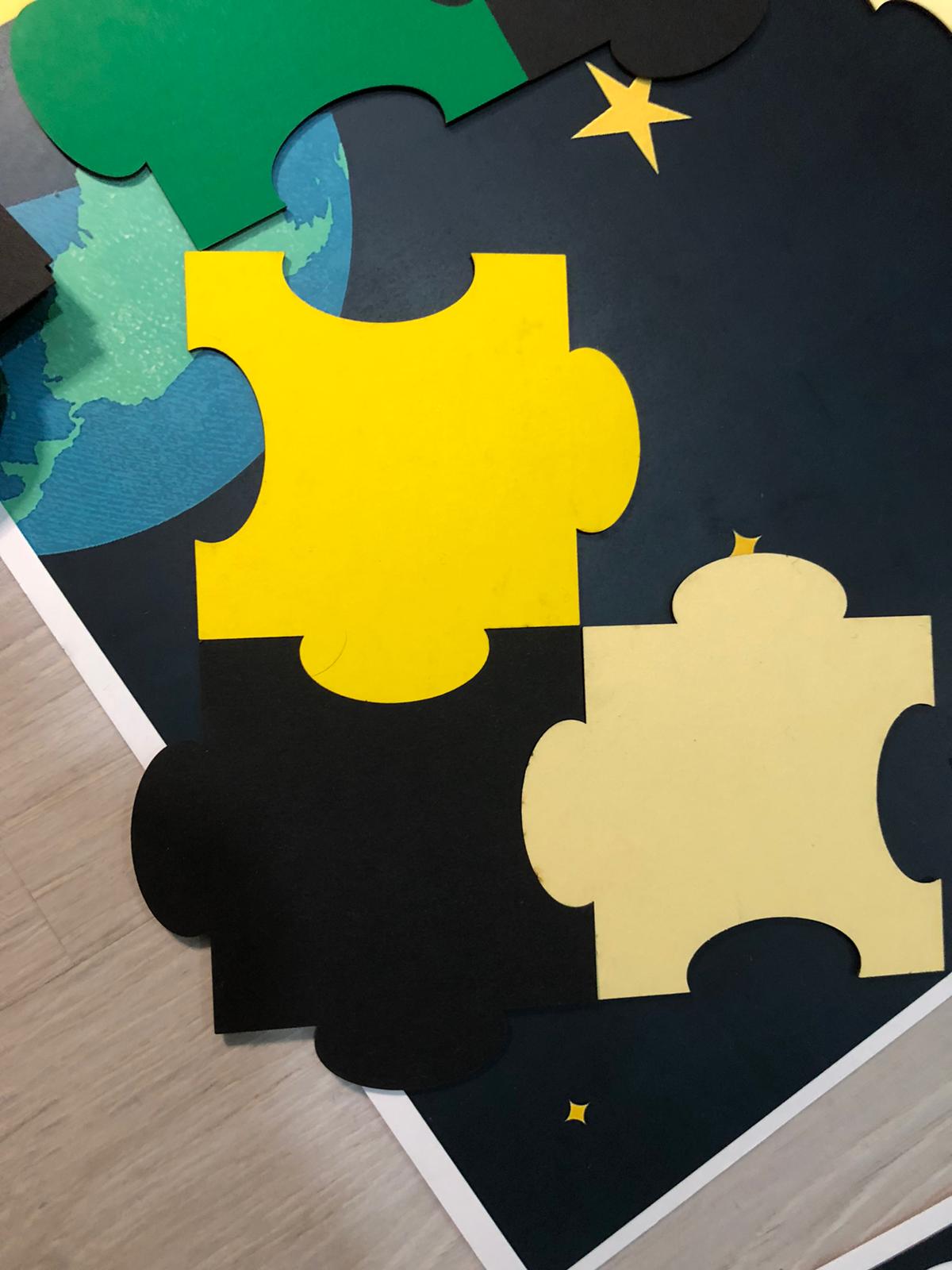
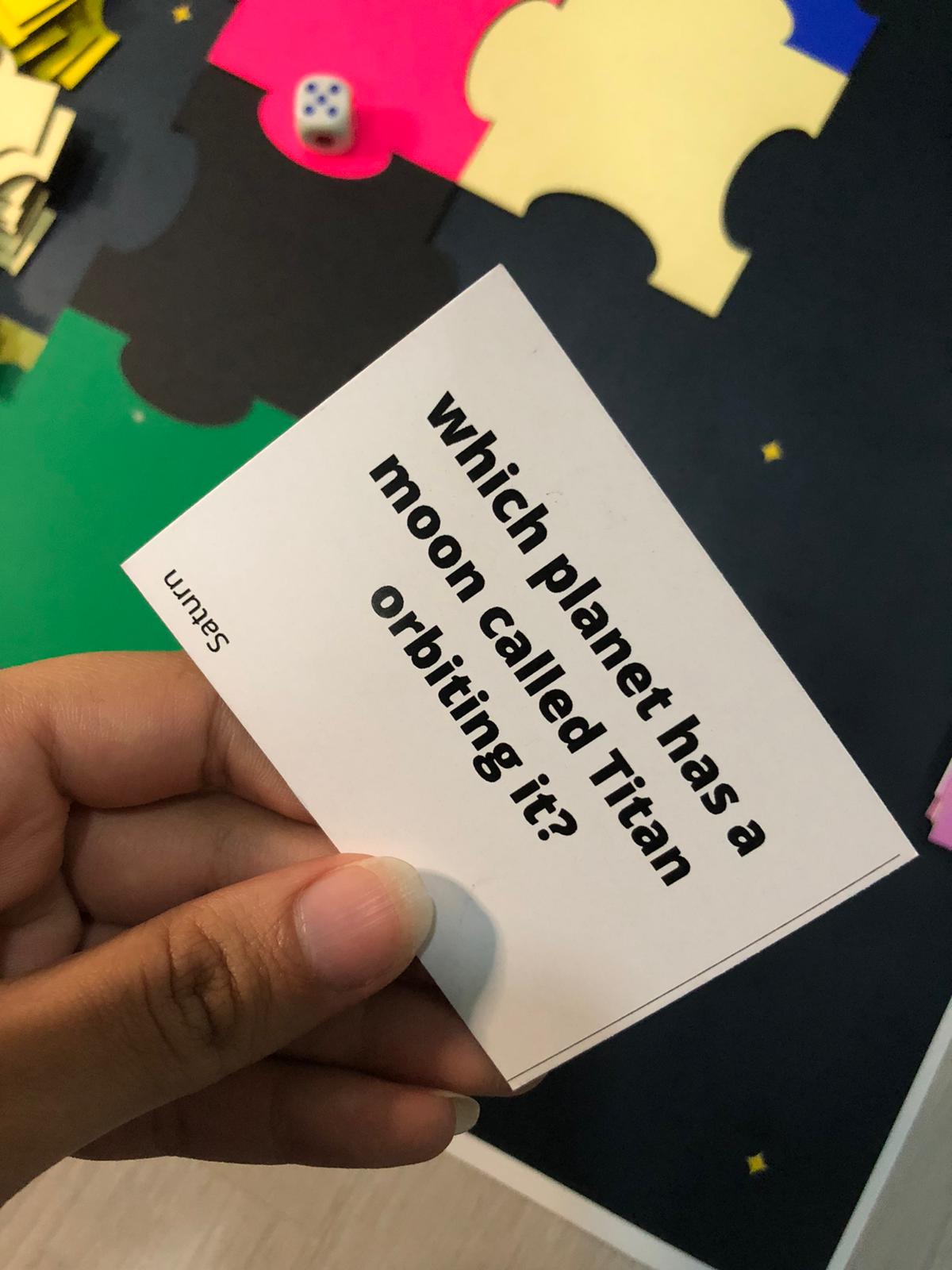
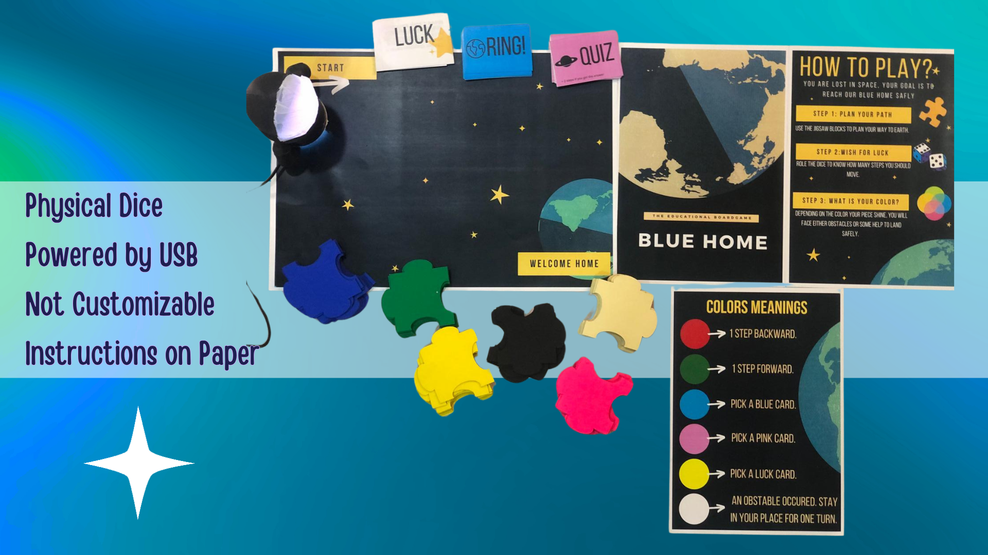
Blue Home is an educational interactive board game, played by 1+ and for ages 6+. Basically, it is for anyone who wants to get to know more about the planets around us and their moons in a fun way. It is about an astronaut who is lost in space and his goal is to reach his Blue Home safely, facing all the quizzes, obstacles, and using all needed help. You are that astronaut and your goal is to reach the Blue Home.
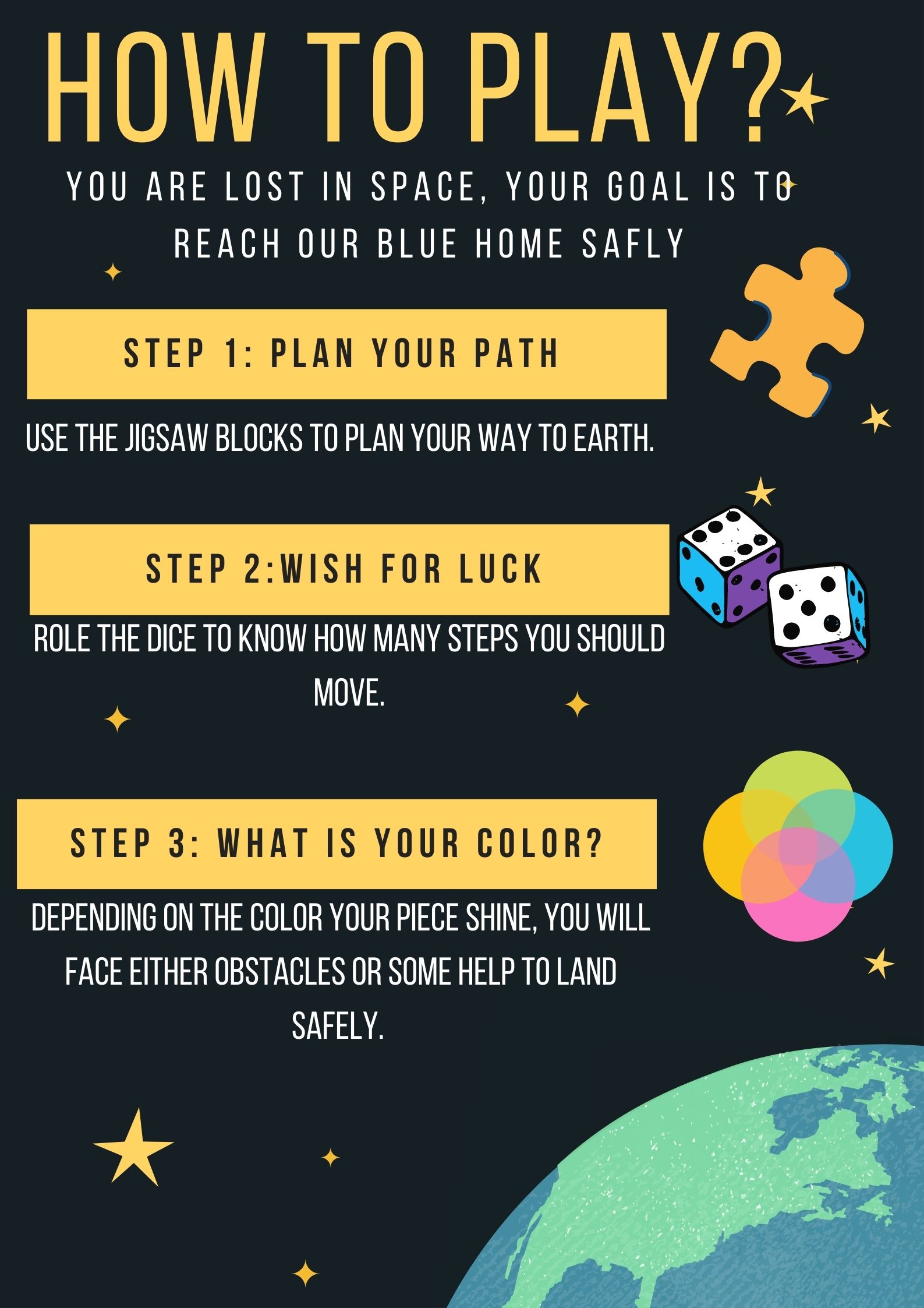
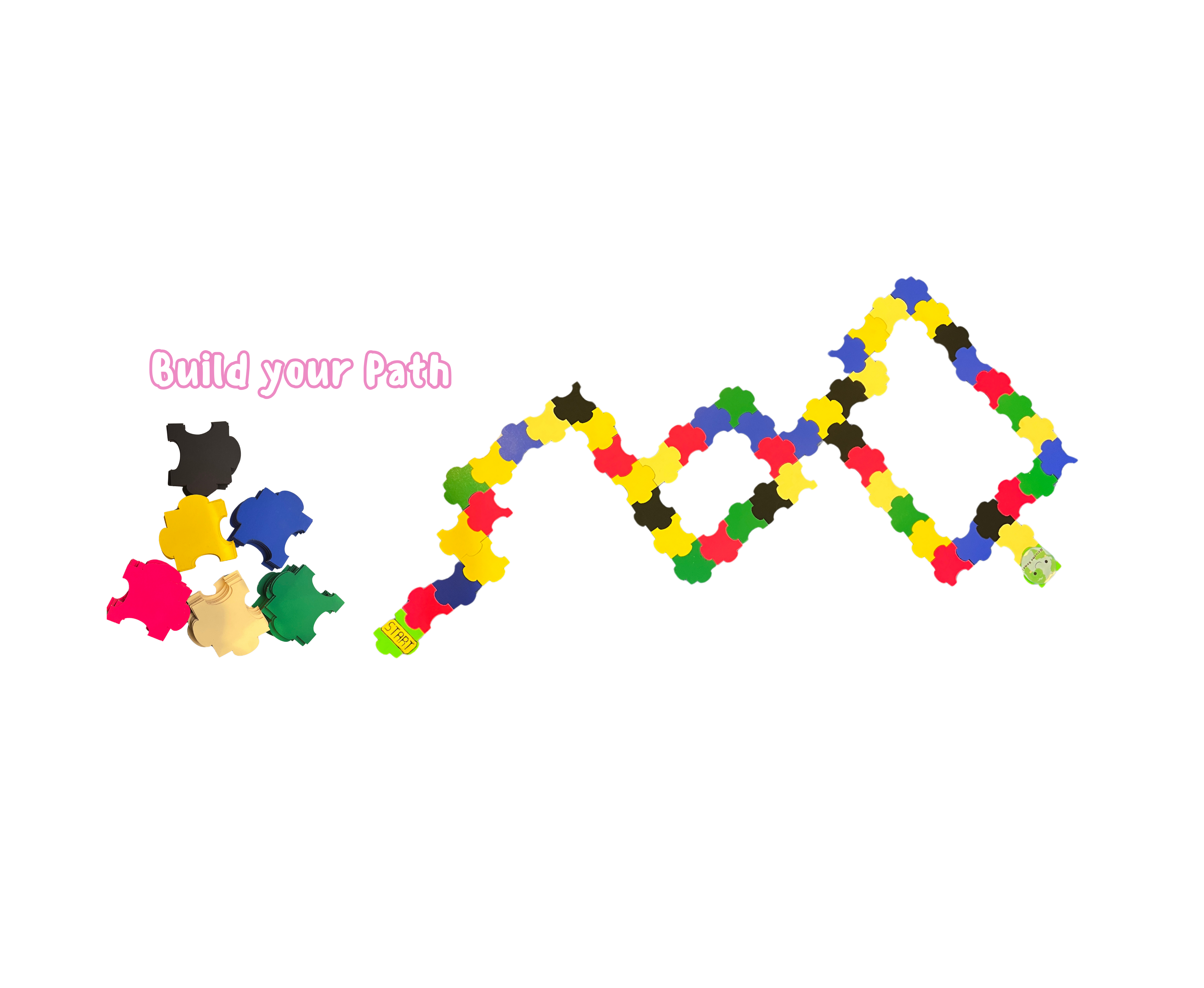
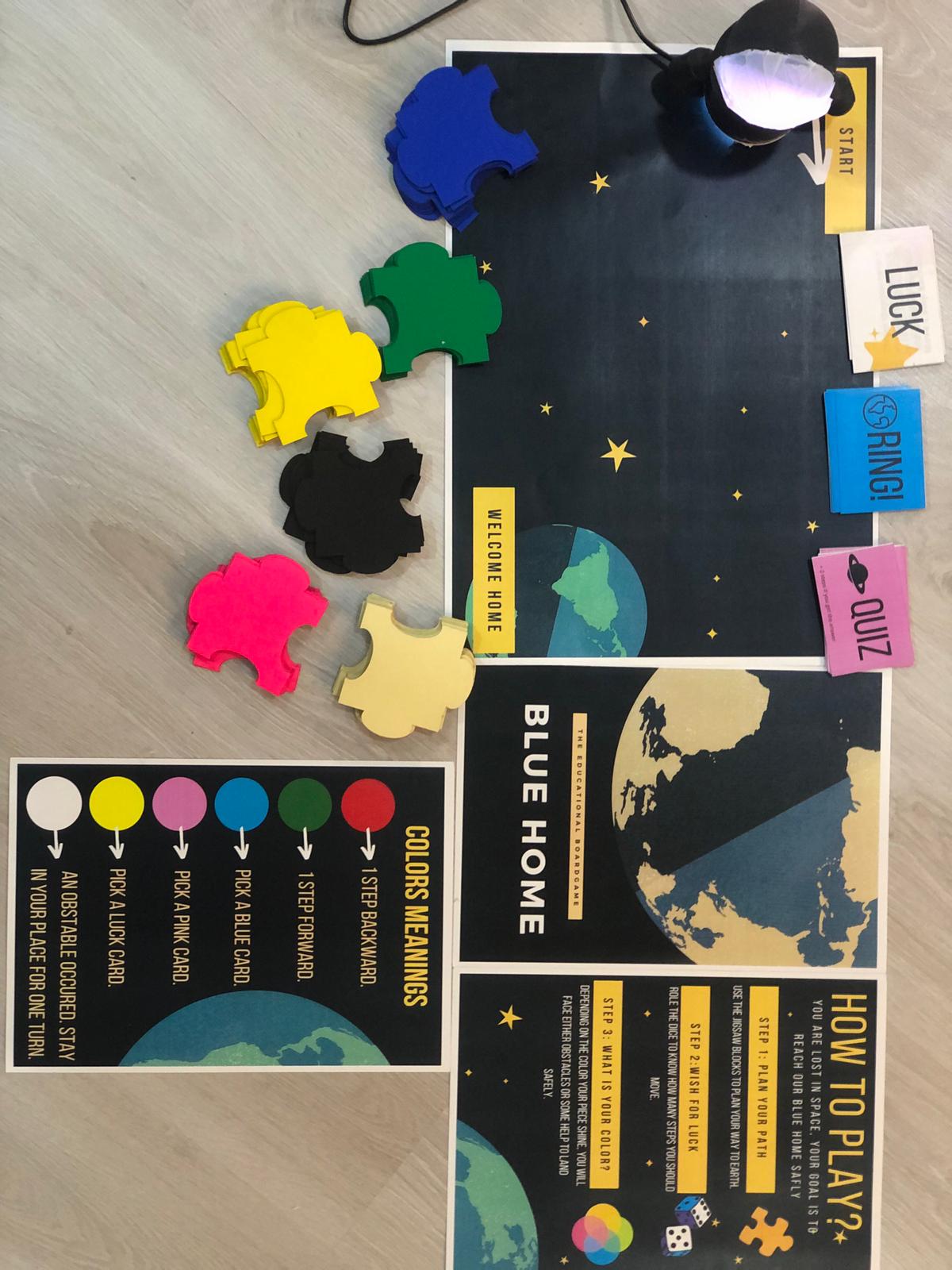
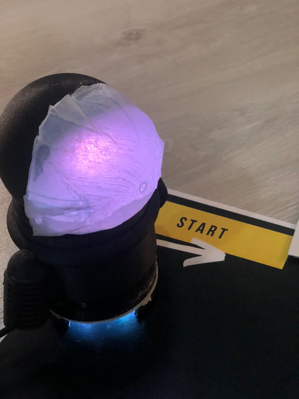
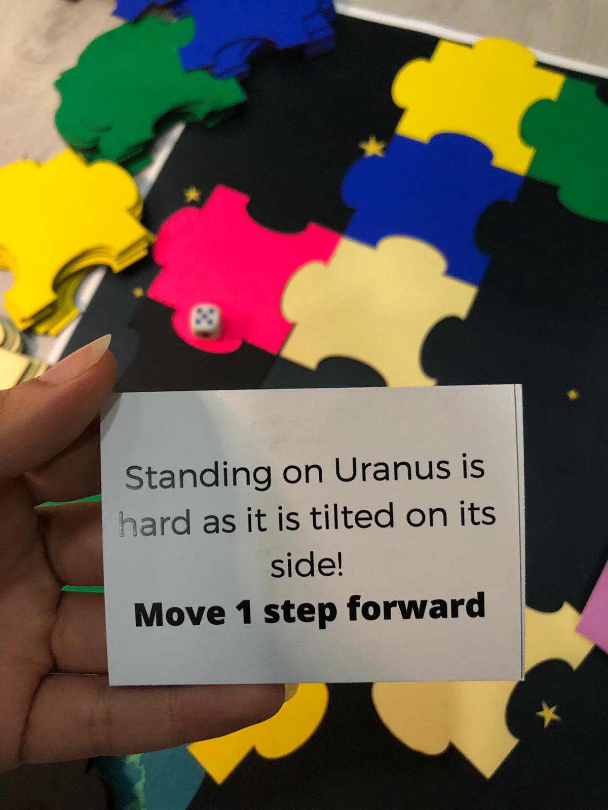
How To Play To Play Blue Home, first build your path using the colored jigsaw pieces. This will be your board that you will move on. After that, role the dice, and move your astronaut. The astronaut will then react randomly by vibrating and shining different colors. Depending on the color your piece shine, you will either move forward or backward, or pick a card.
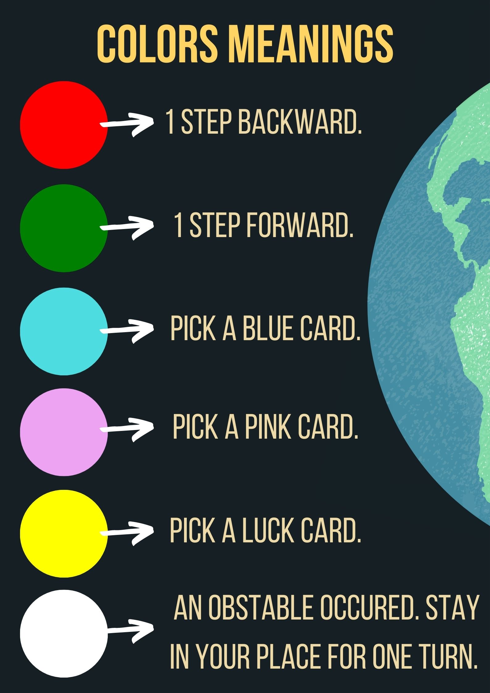
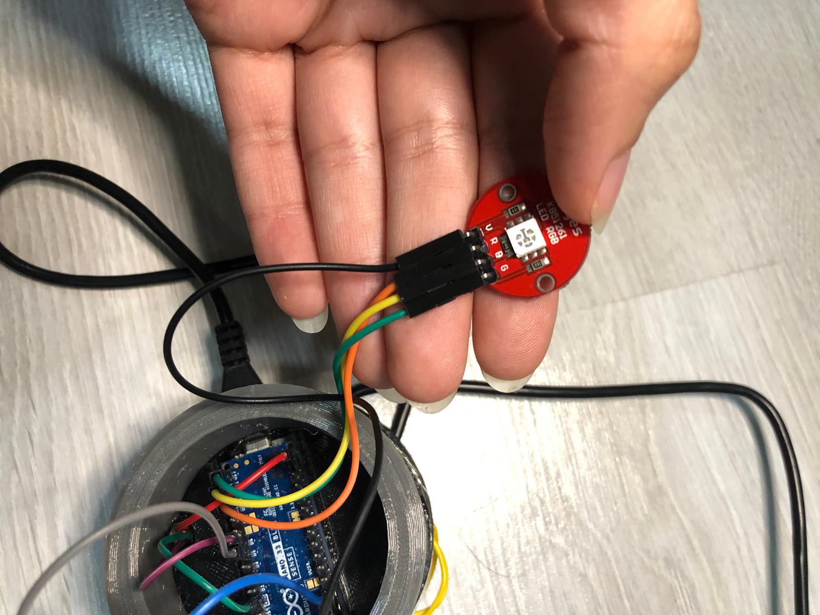
How does it work The main component of this game is the RGB built-in sensor in the Arduino. It is placed downward to detect the color of the jigsaw piece it is on and based on that there will be various reactions from the RGB LED.
| Qty | Description |
|---|---|
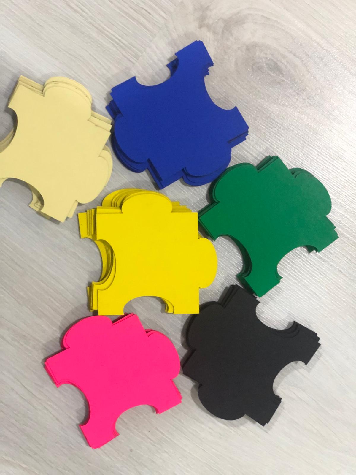
| 6 | Different colors 15mm Cardboard |
| 1 | RGB LED |
| 1 | Arduino Nano 33 BLE Sense |
| 2 | Addressable RGB LED Strips each with 3 LEDs |
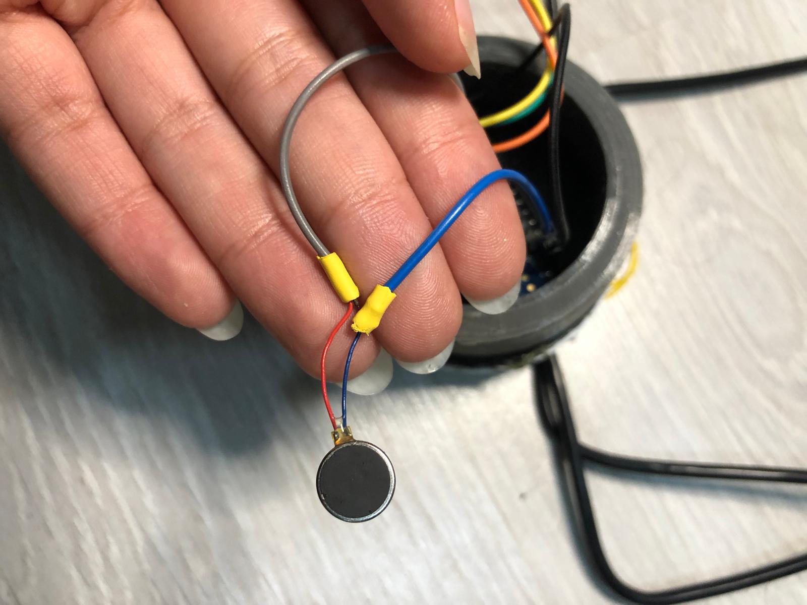
| 1 | Vibrating Mini |
| 1 | 3D printed Astronaut Piece |
| 30 | Printed Cards |
| 1 | Dice |
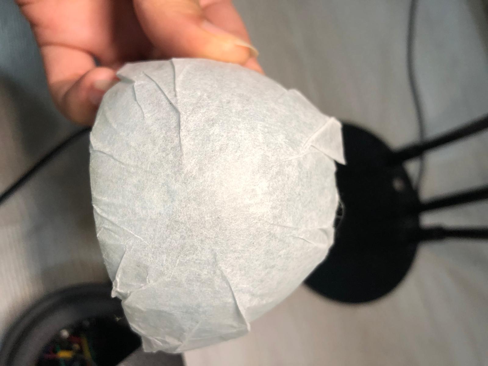
| 1 | Diffusive Paper |
The making of this board game consists of three main steps, fabrication, connecting the electronic parts and coding the game.
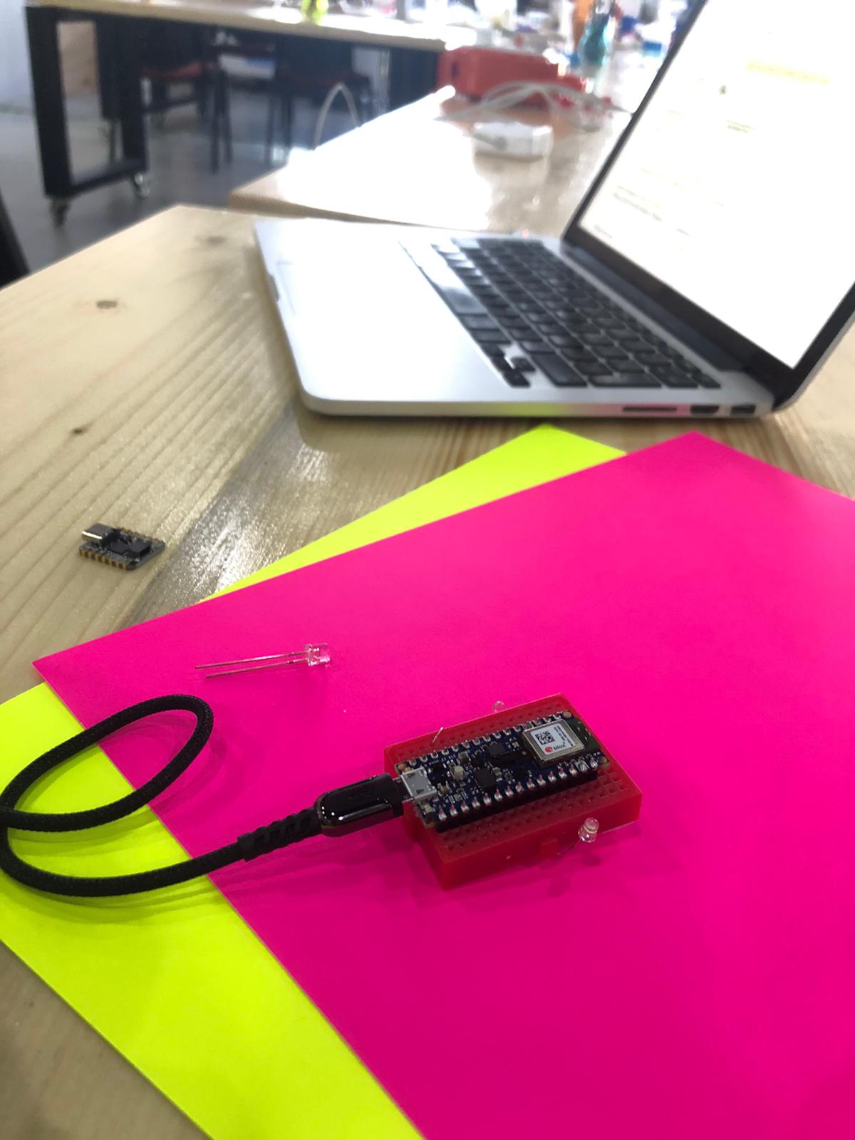
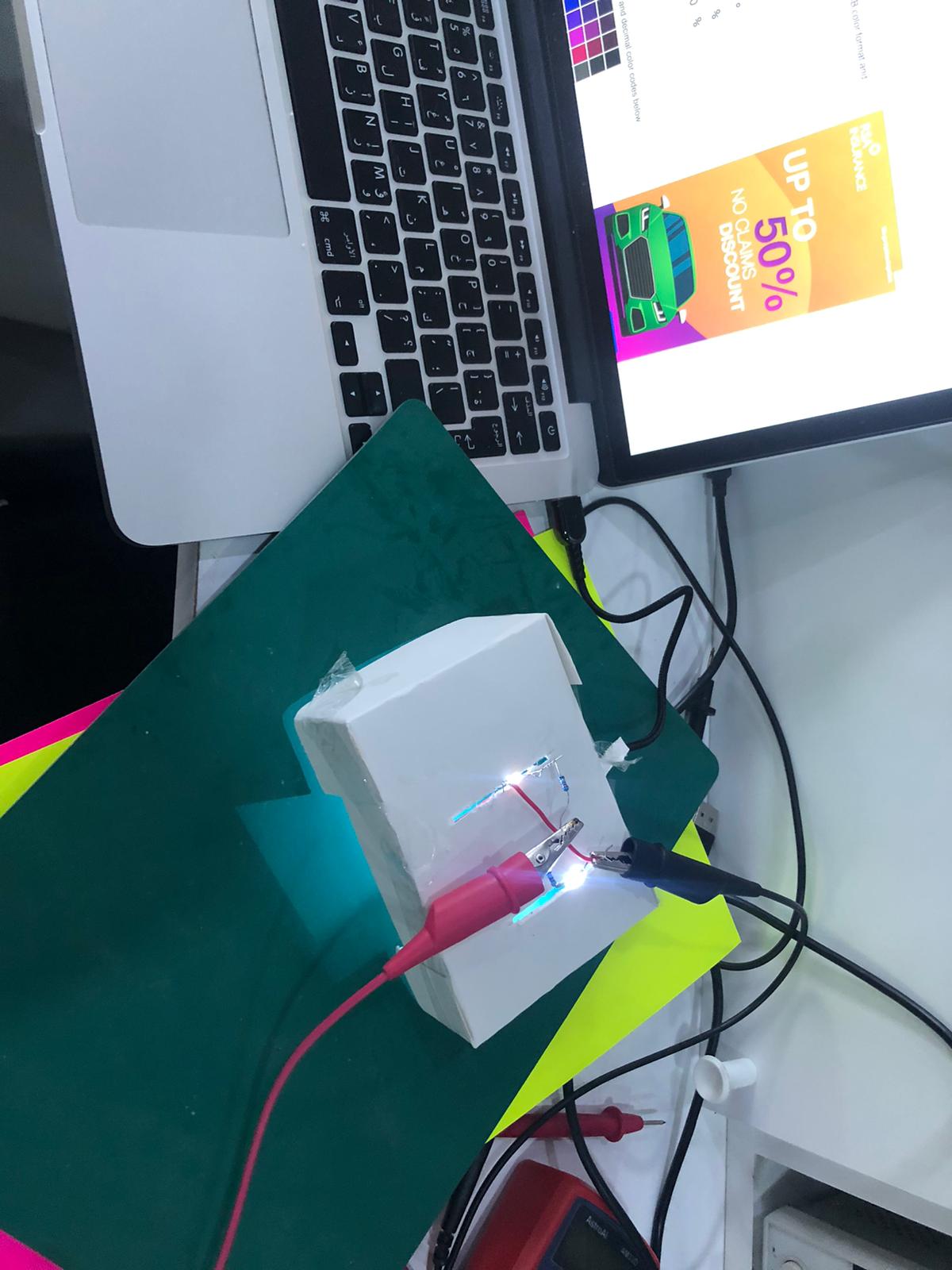
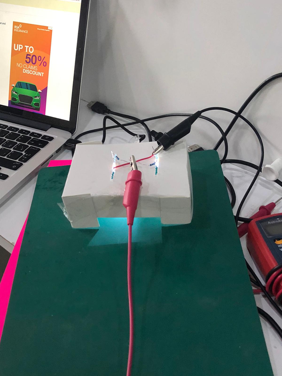
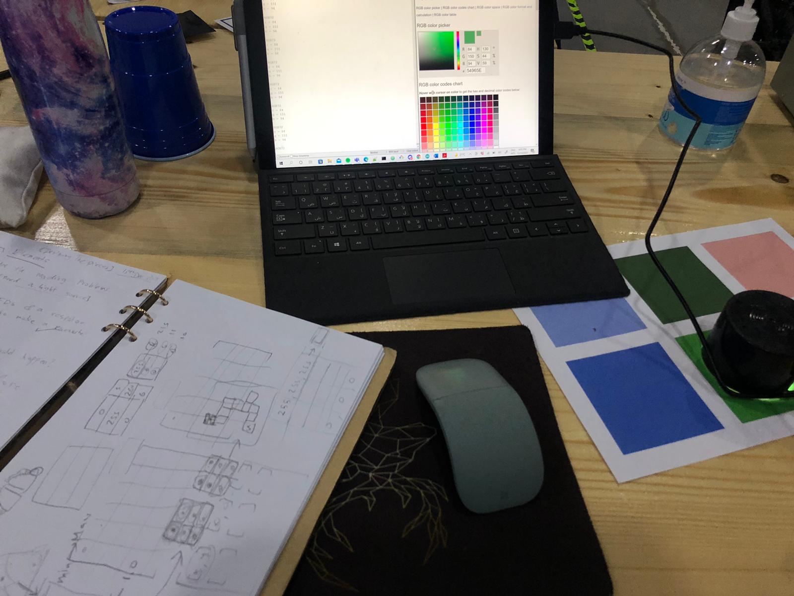
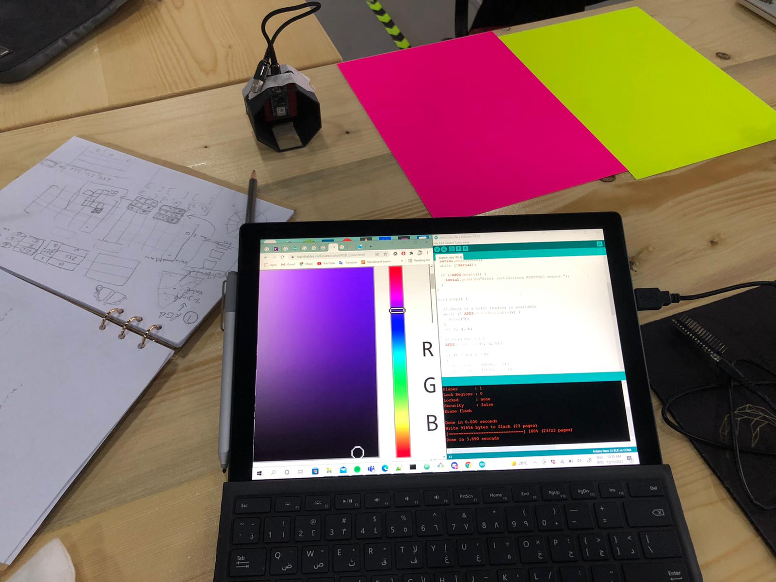
Before going and doing the fabrication, I started by testing the conditions that the RGB sensor will work in.
I started by making a sample model prototype using cardboard, and tested the reading of the sensor.
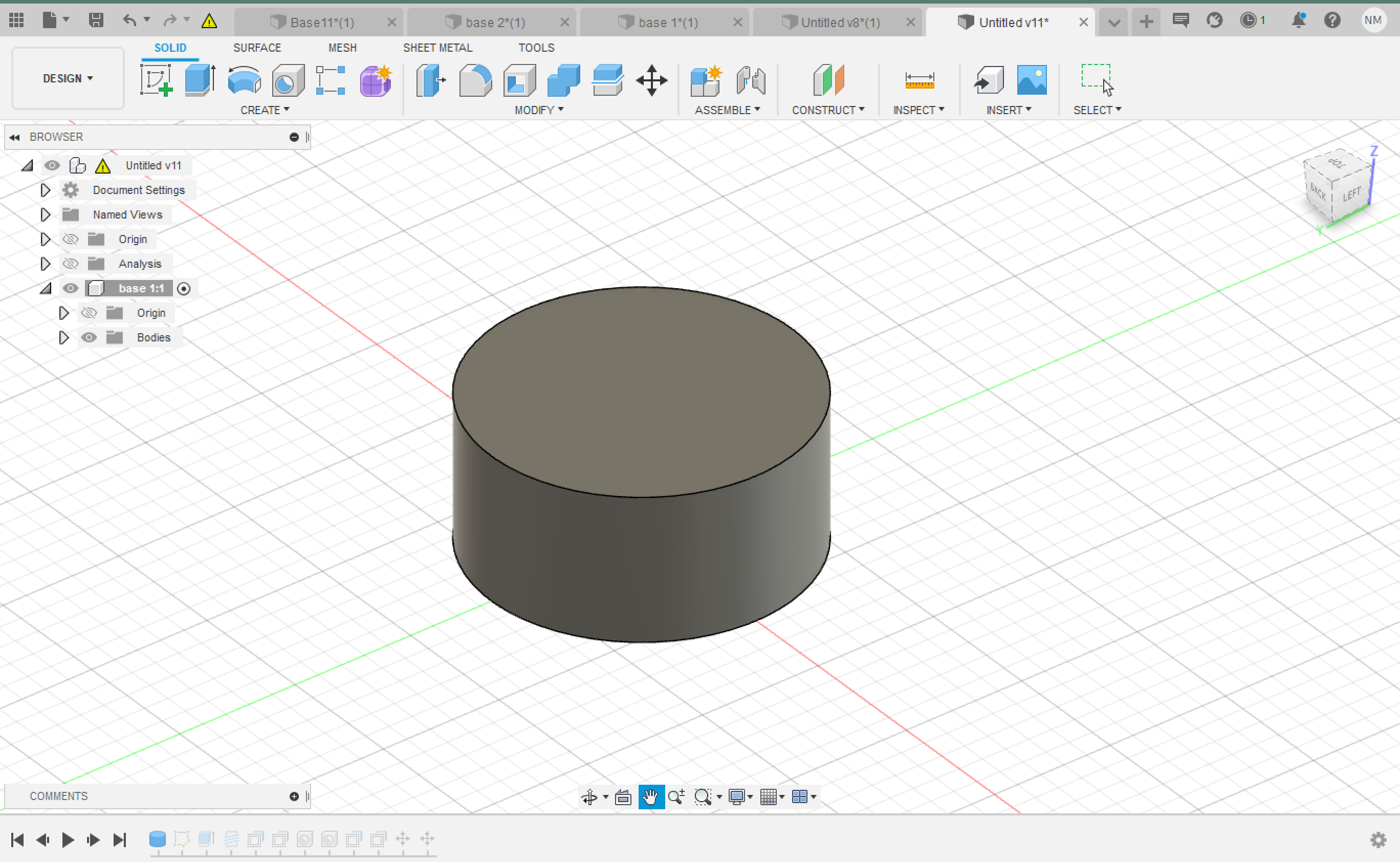
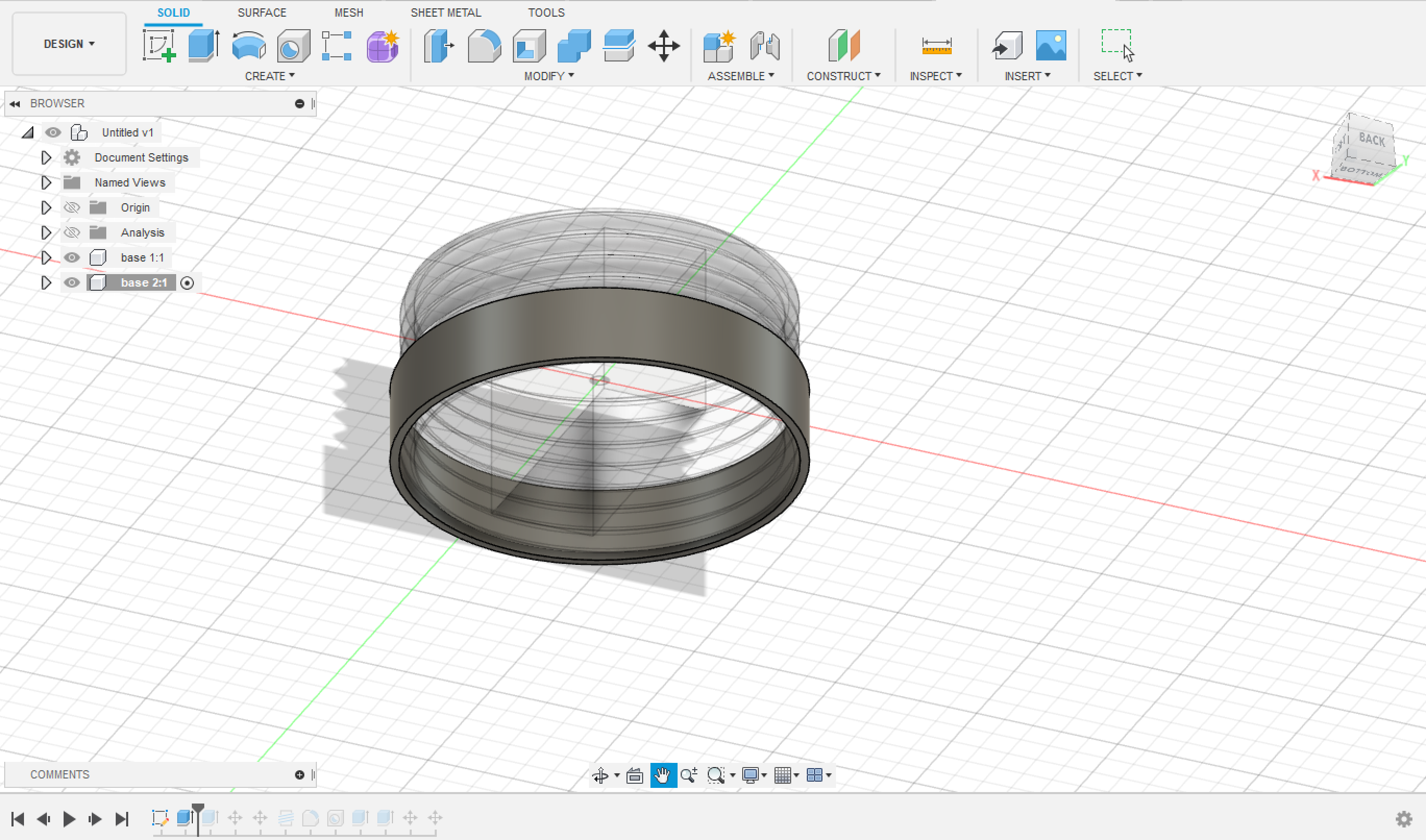
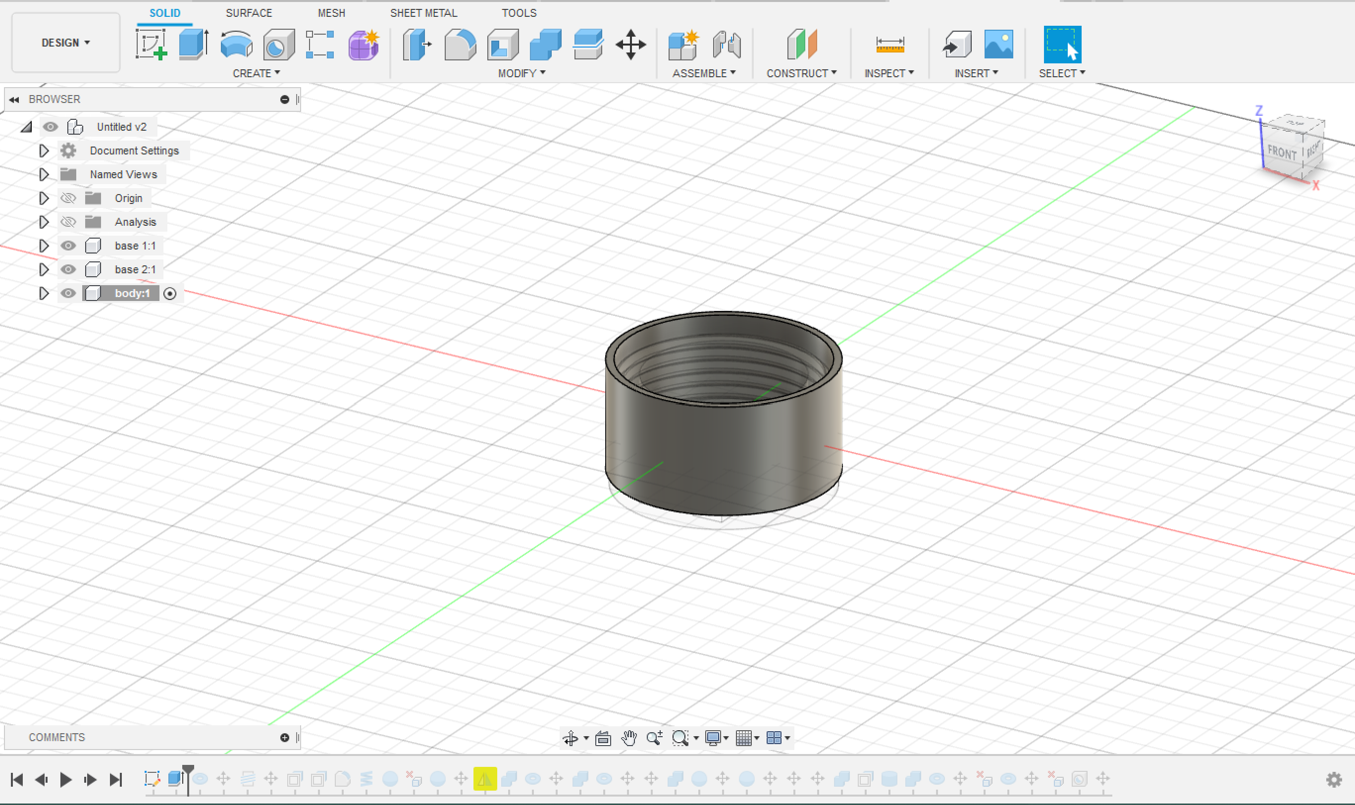
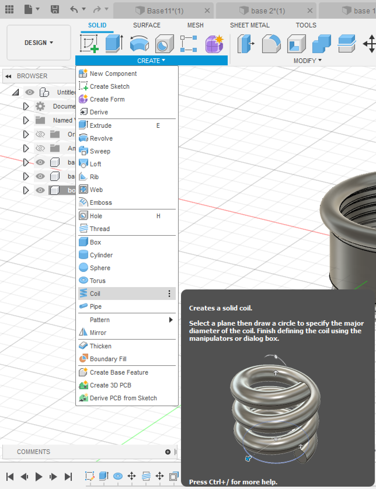
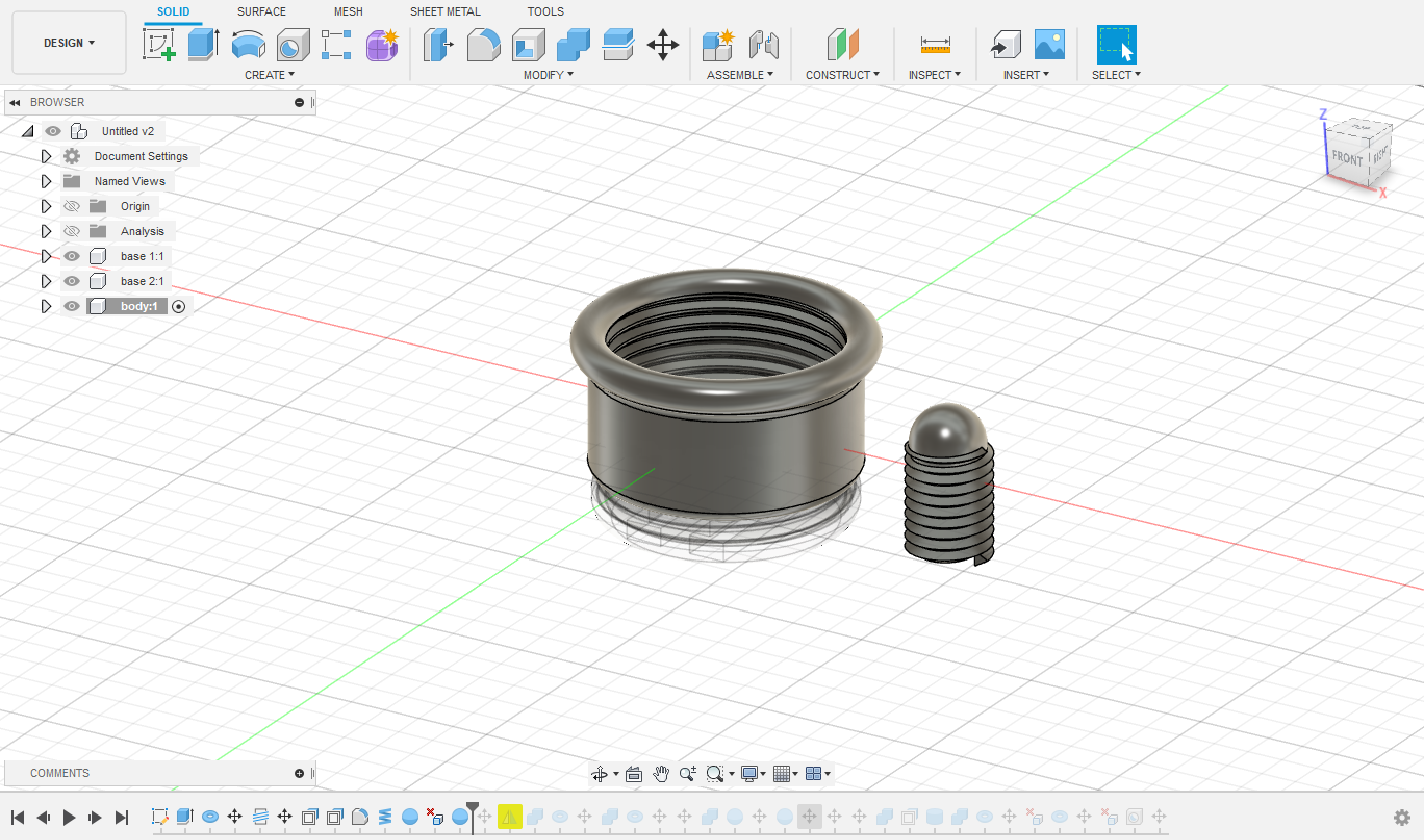
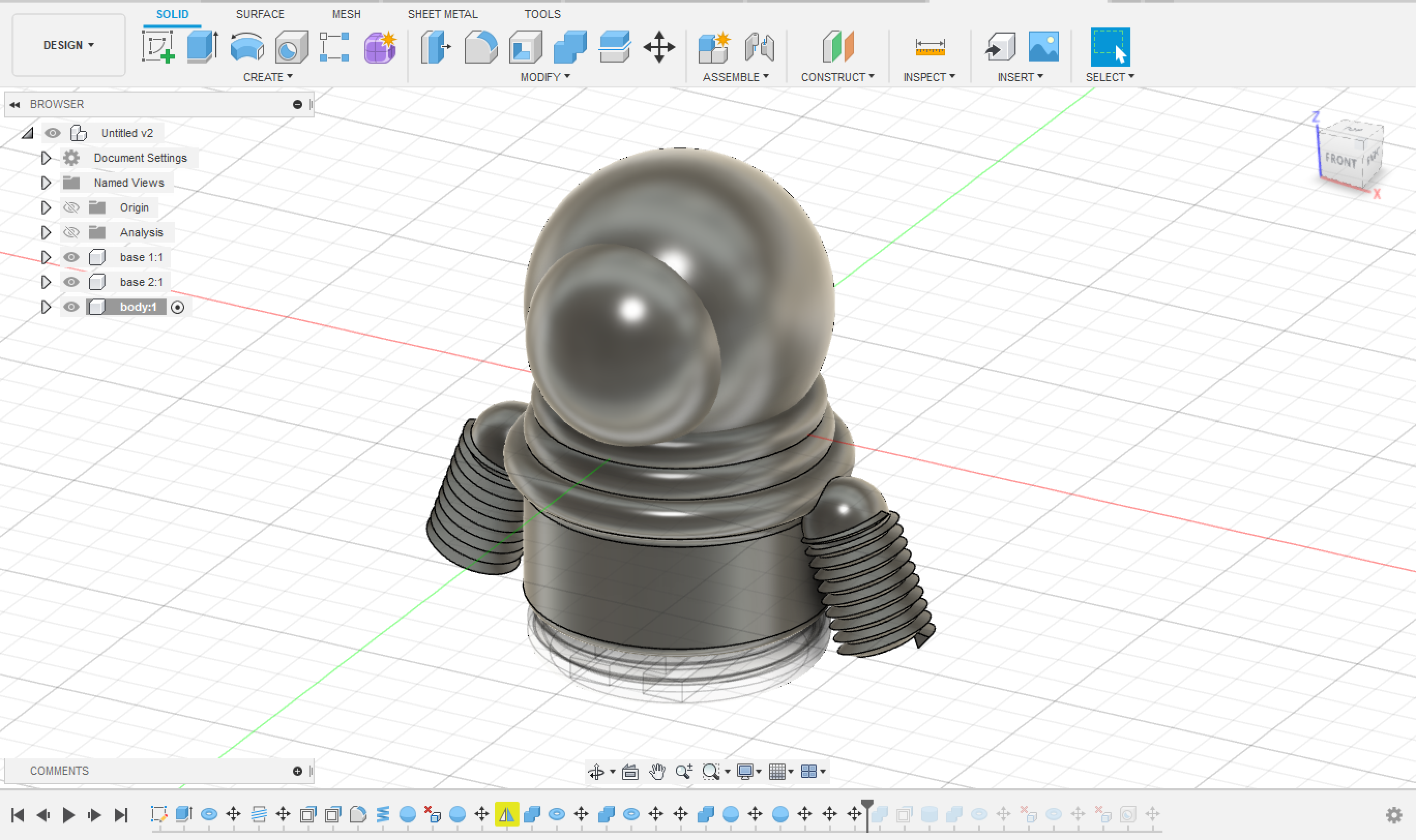
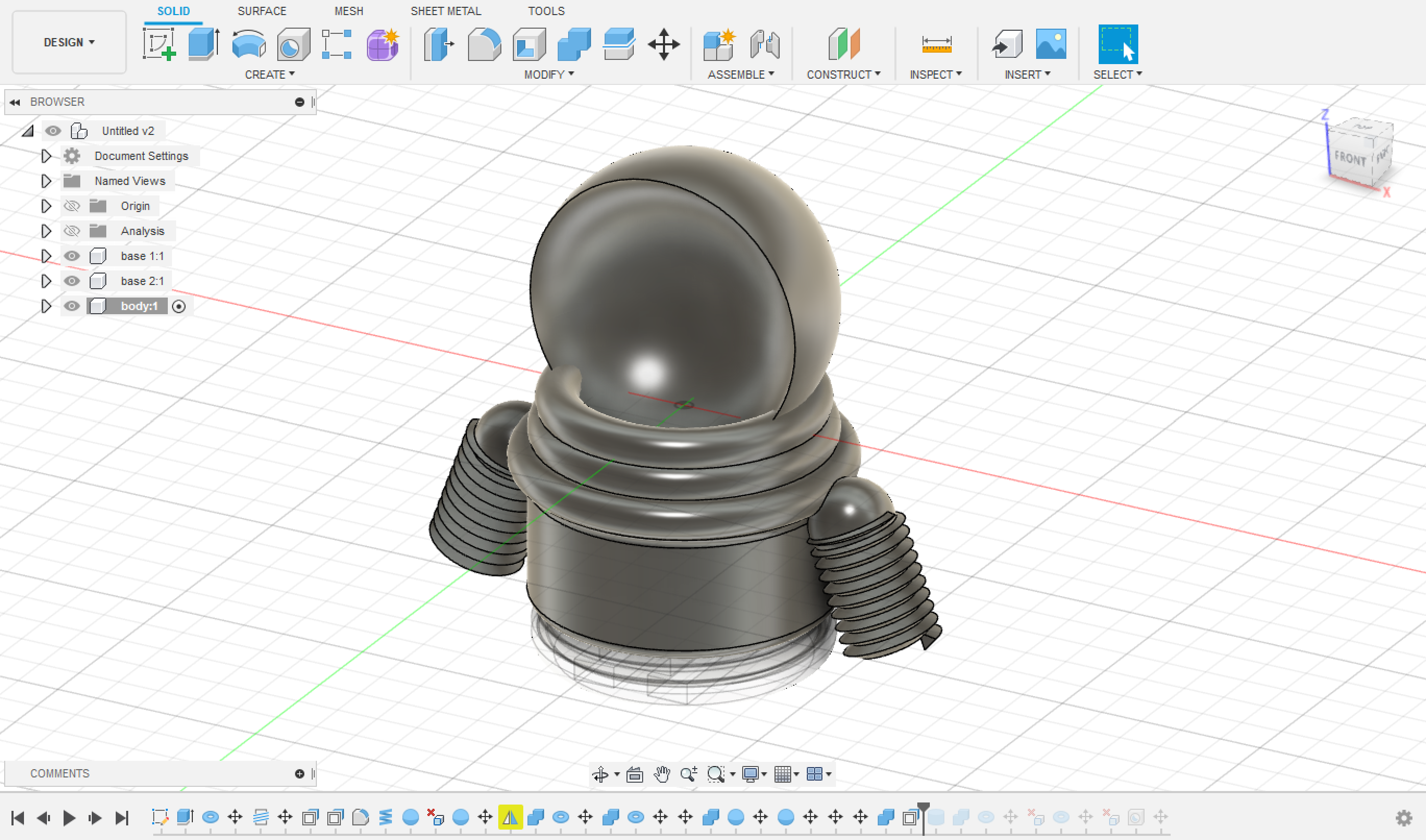
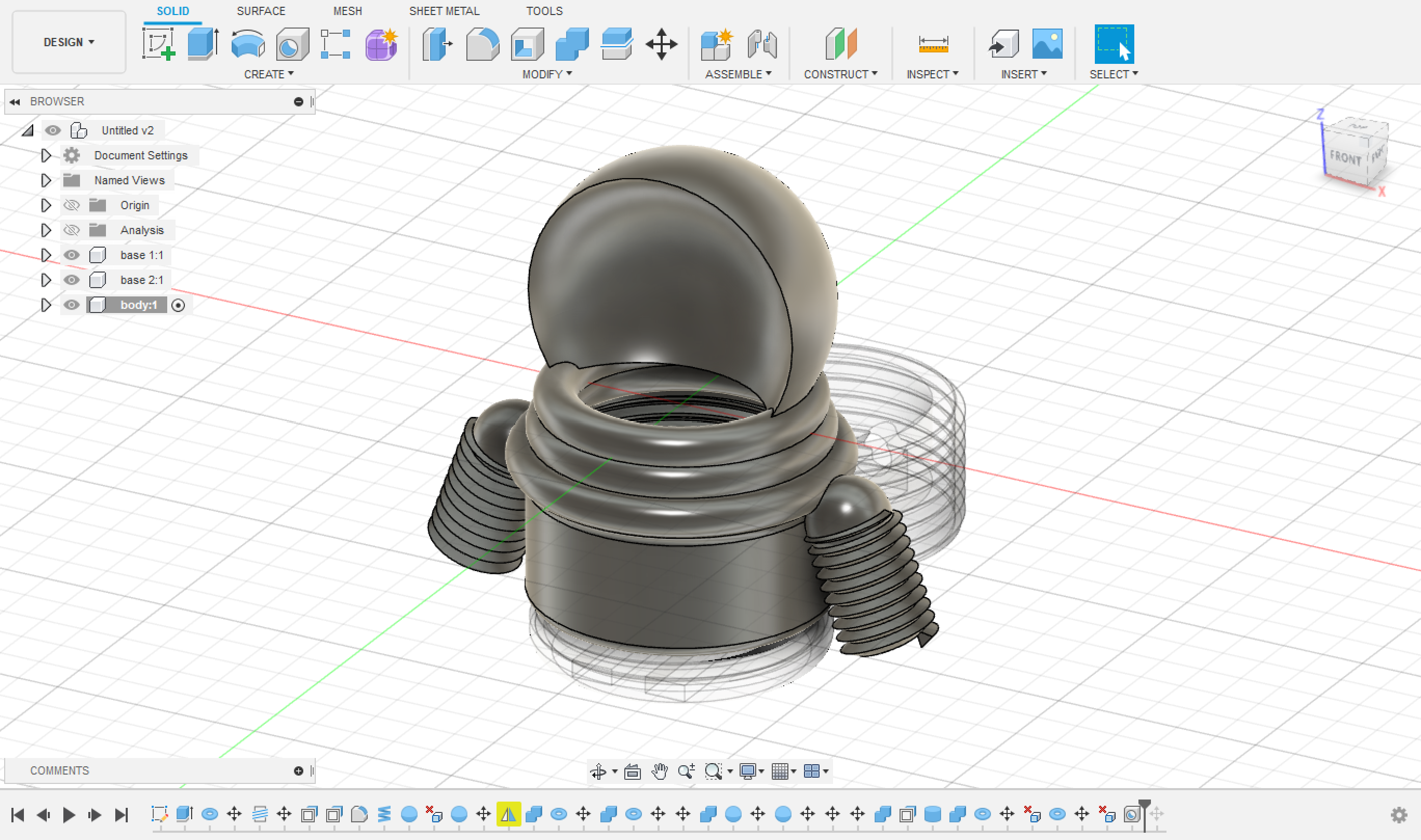
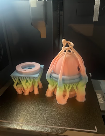
After knowing everything I need to include in my design for the piece, I then started the process of designing it and printing it.
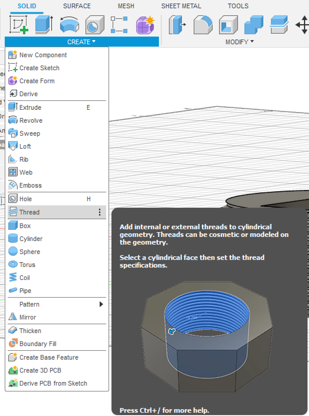
I used Fuion360 for the design, and I did it from scratch.
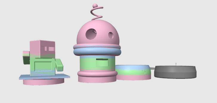
The design consists of three parts:
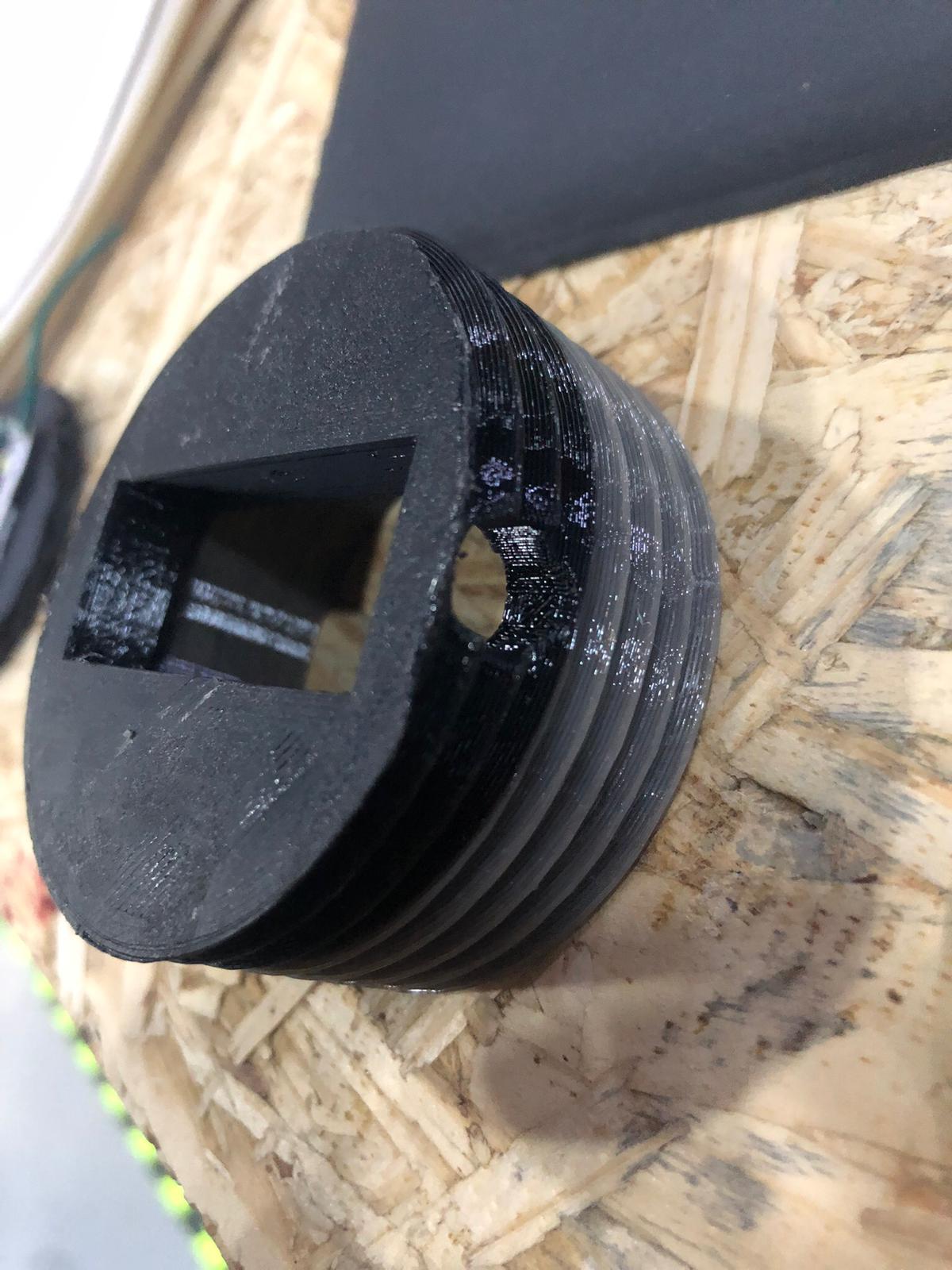
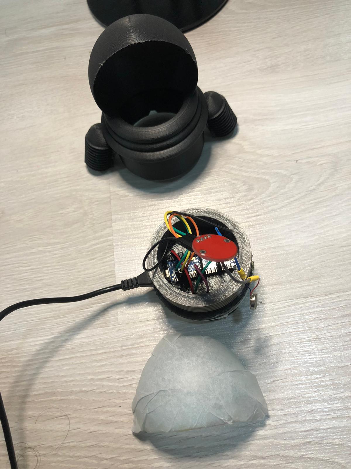
The 1st Base which holds on the Arduino, and it is tighten to the body and the 2nd base. It must have a hole for the USB wire and must be empty for the wires to be connected in the Pinouts of the Arduino.
The 2nd Base which tightens up to the 1st base, and has a placement for LED Strips. It must have a place for the wires of the LED strips to go all the way up and be connected to the pinouts of the Arduino.
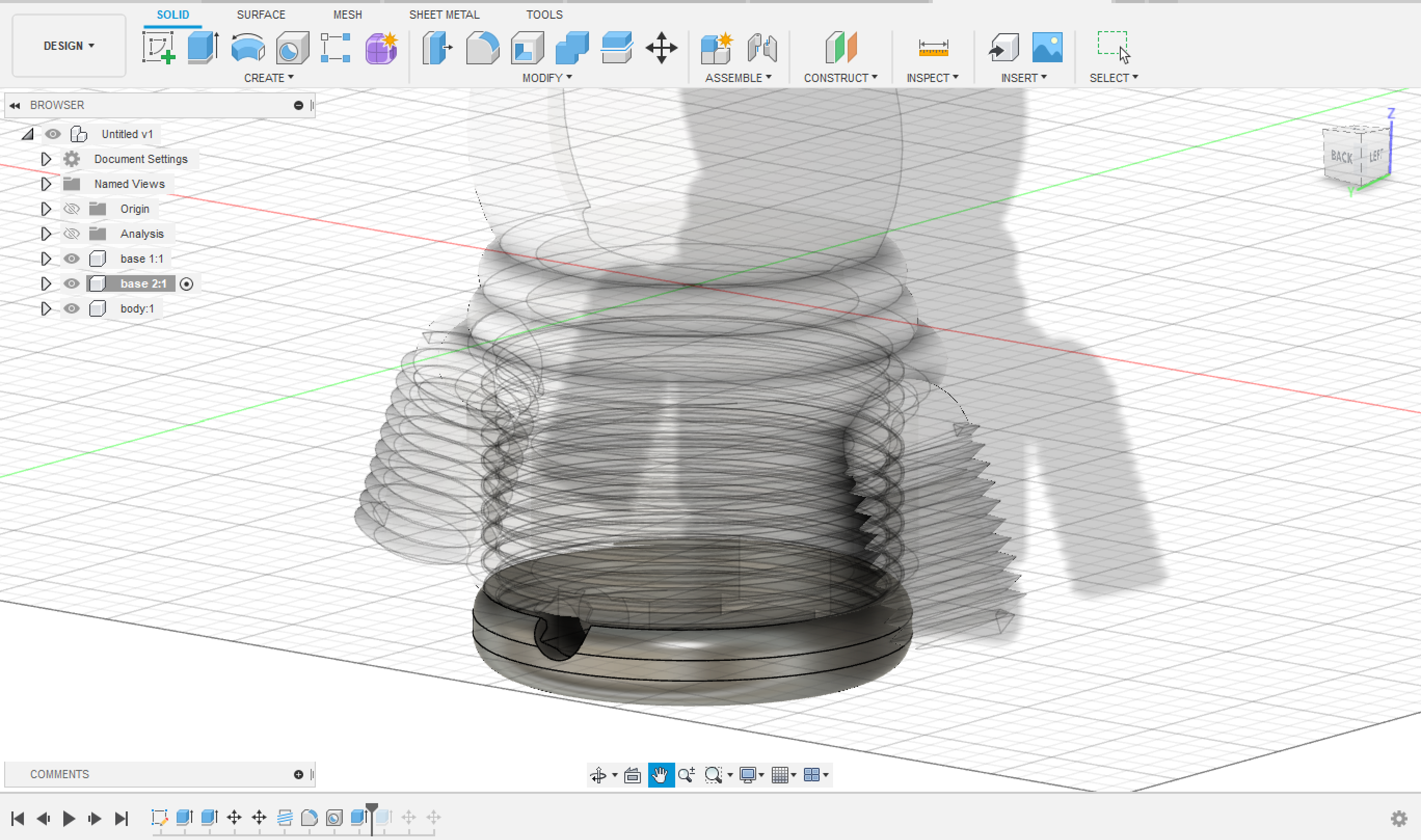
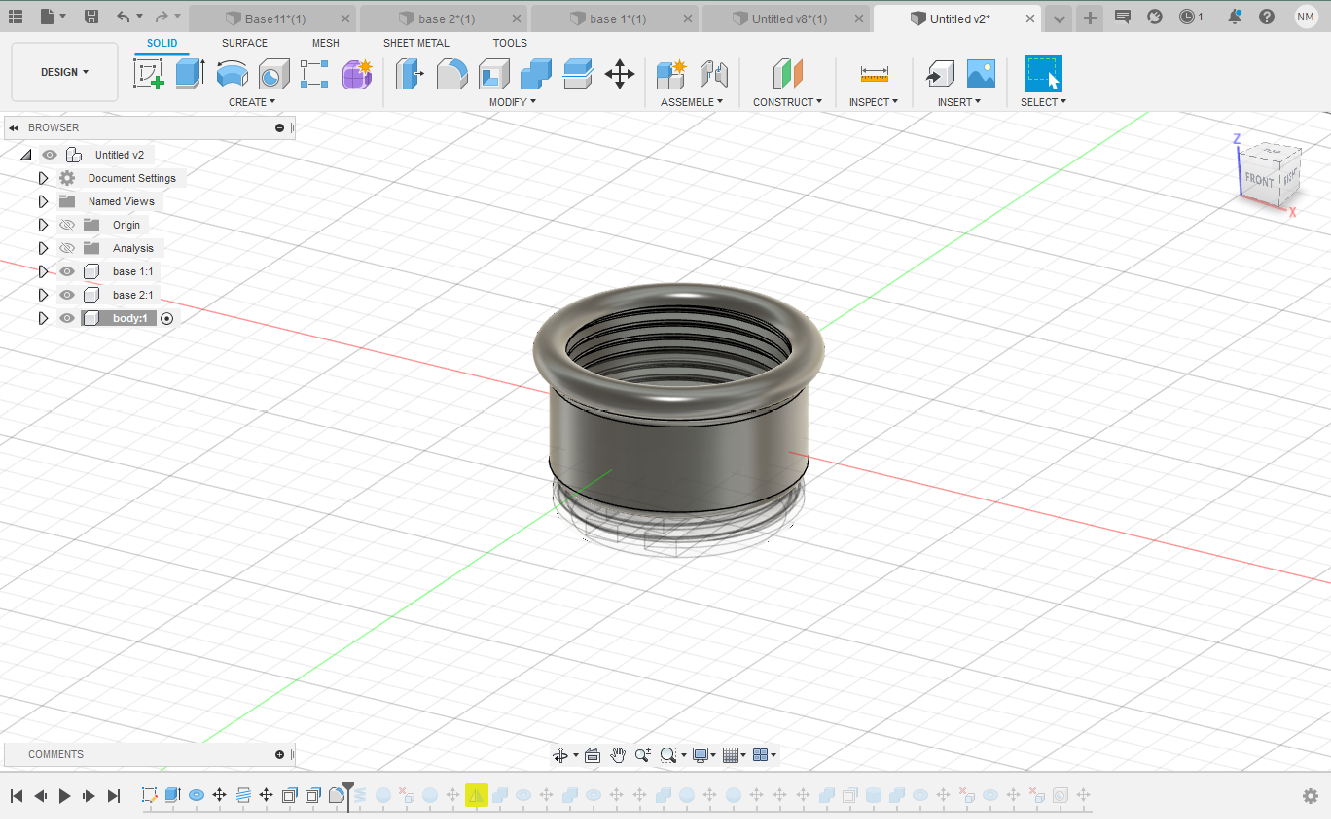
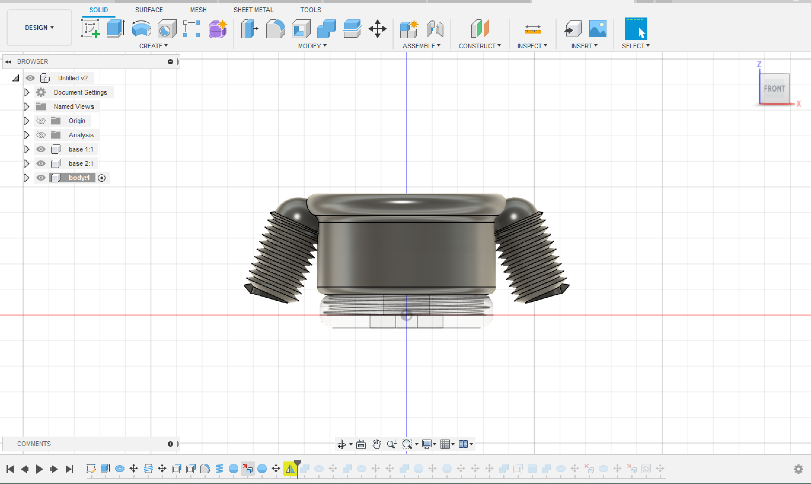
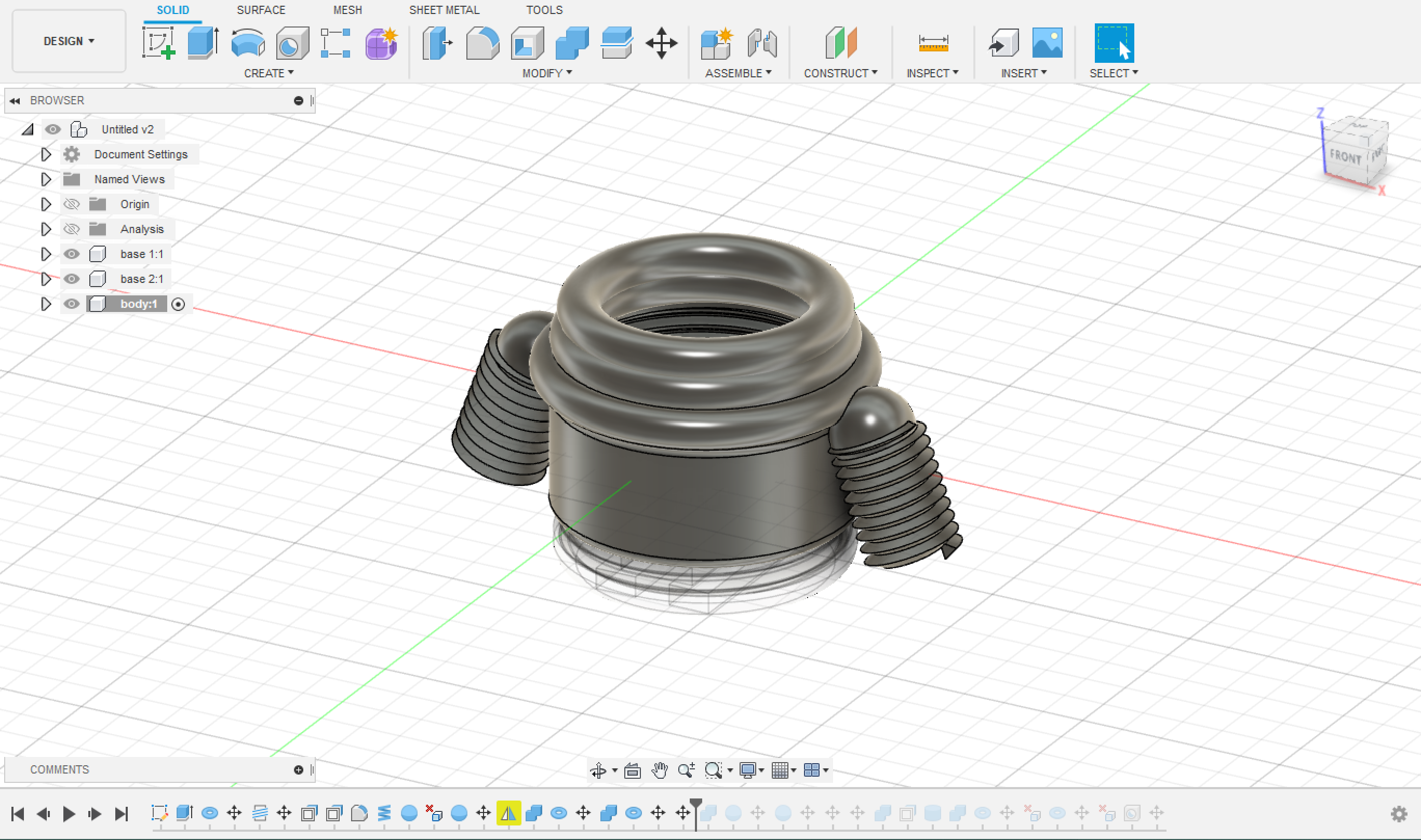
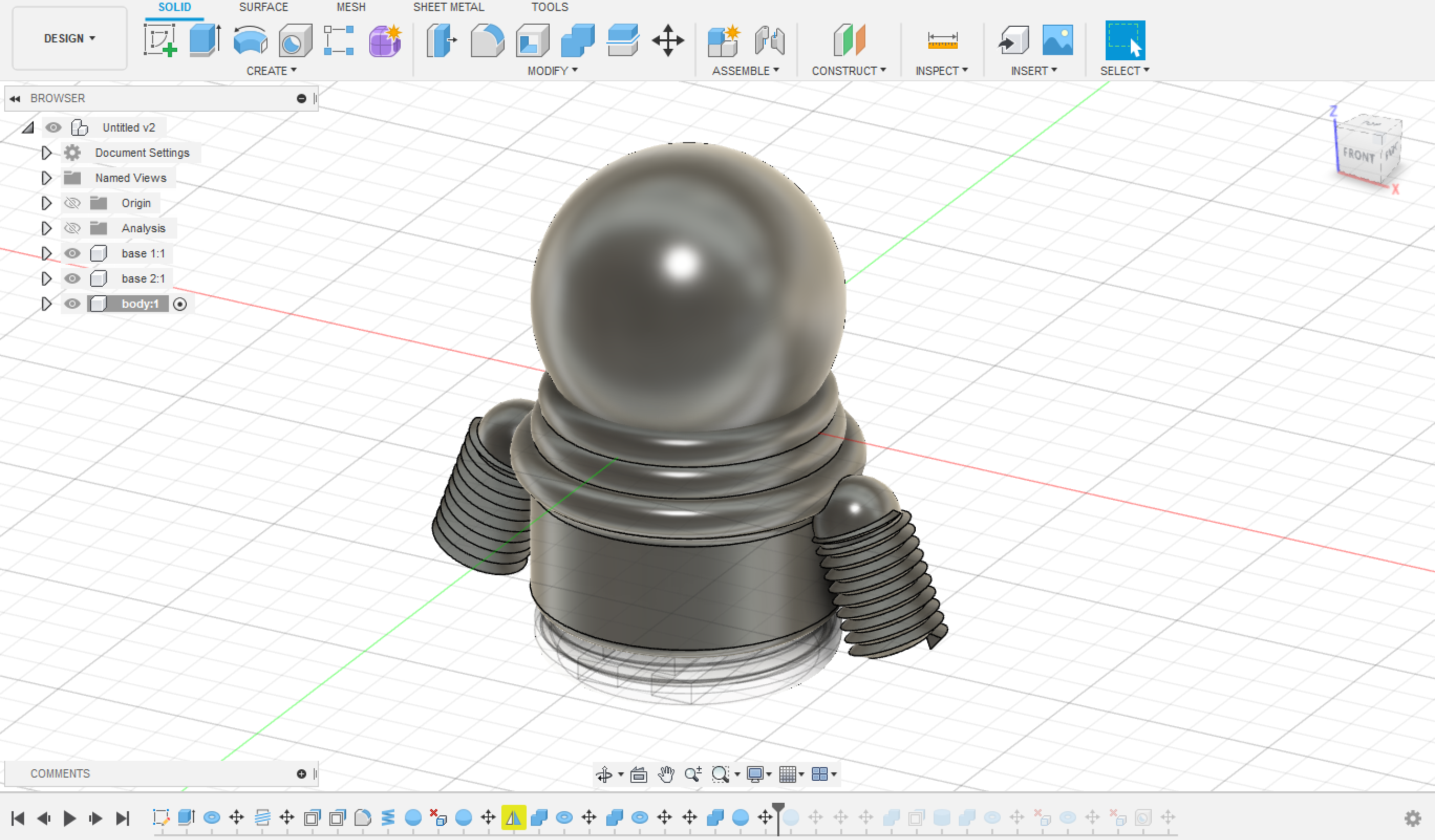
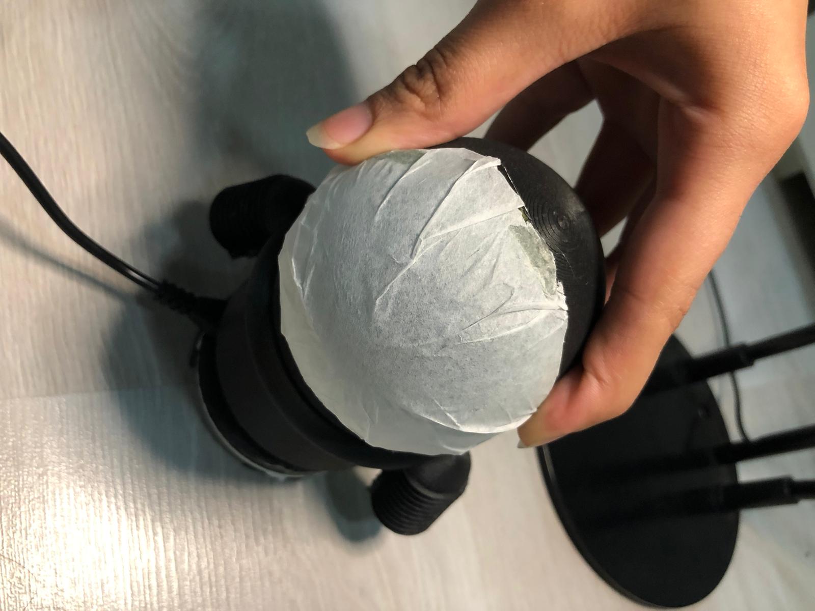
The Body which tighten up to the 1st base and basically it is the shape of the piece. It must be empty from the inside.
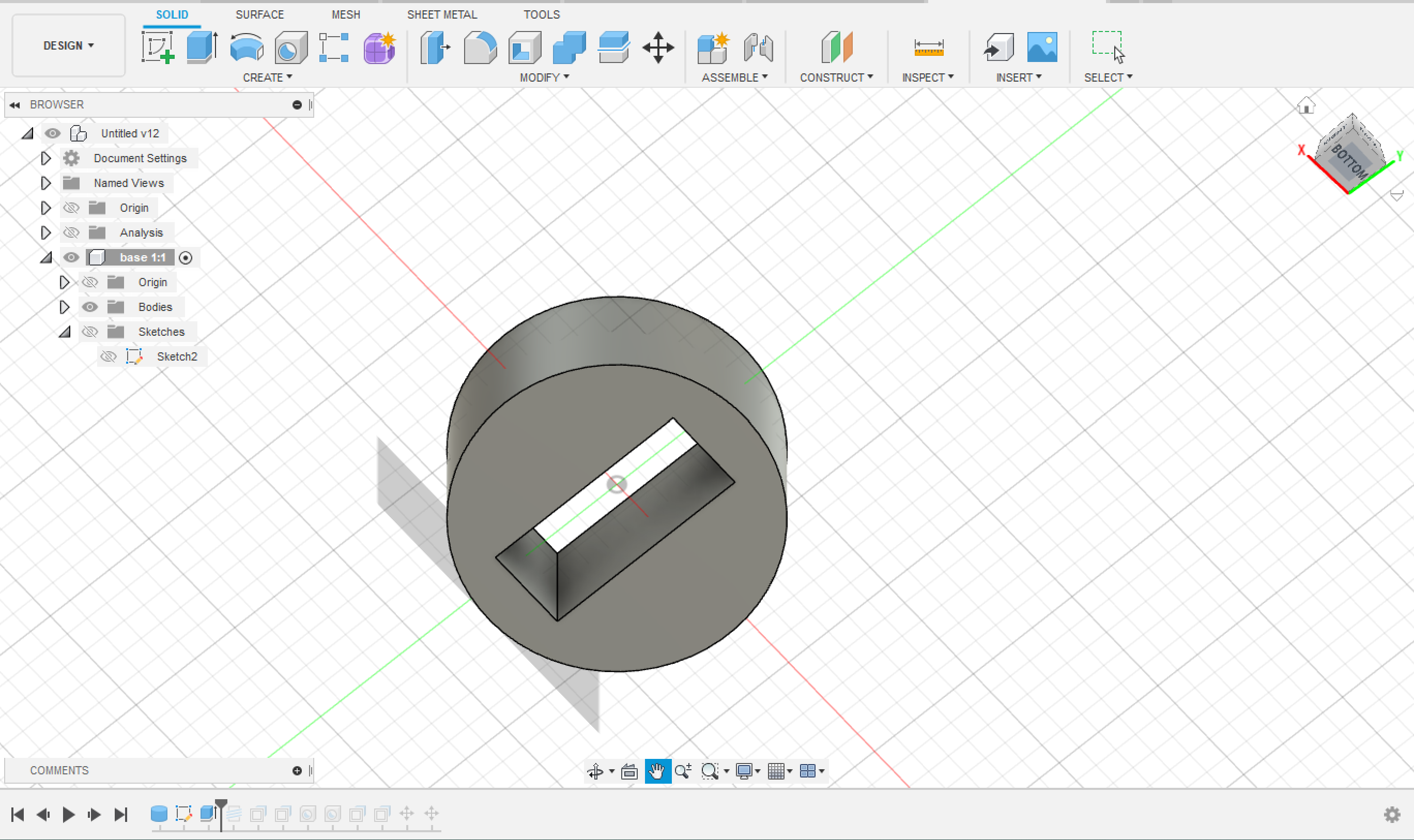
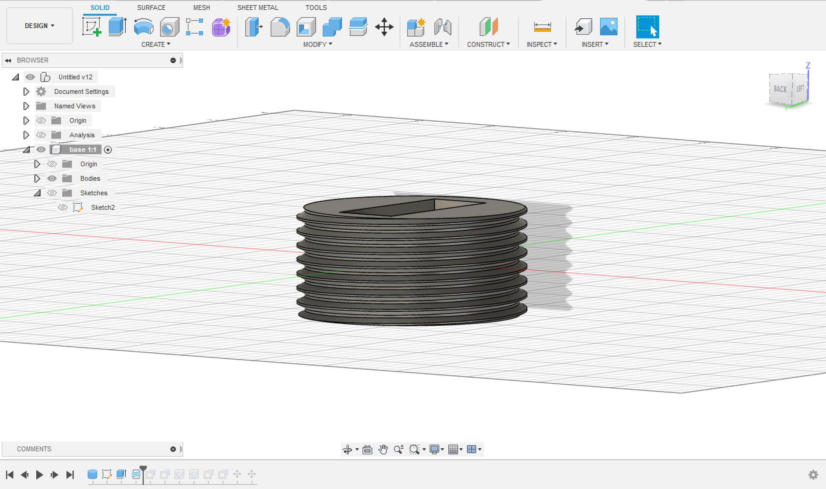
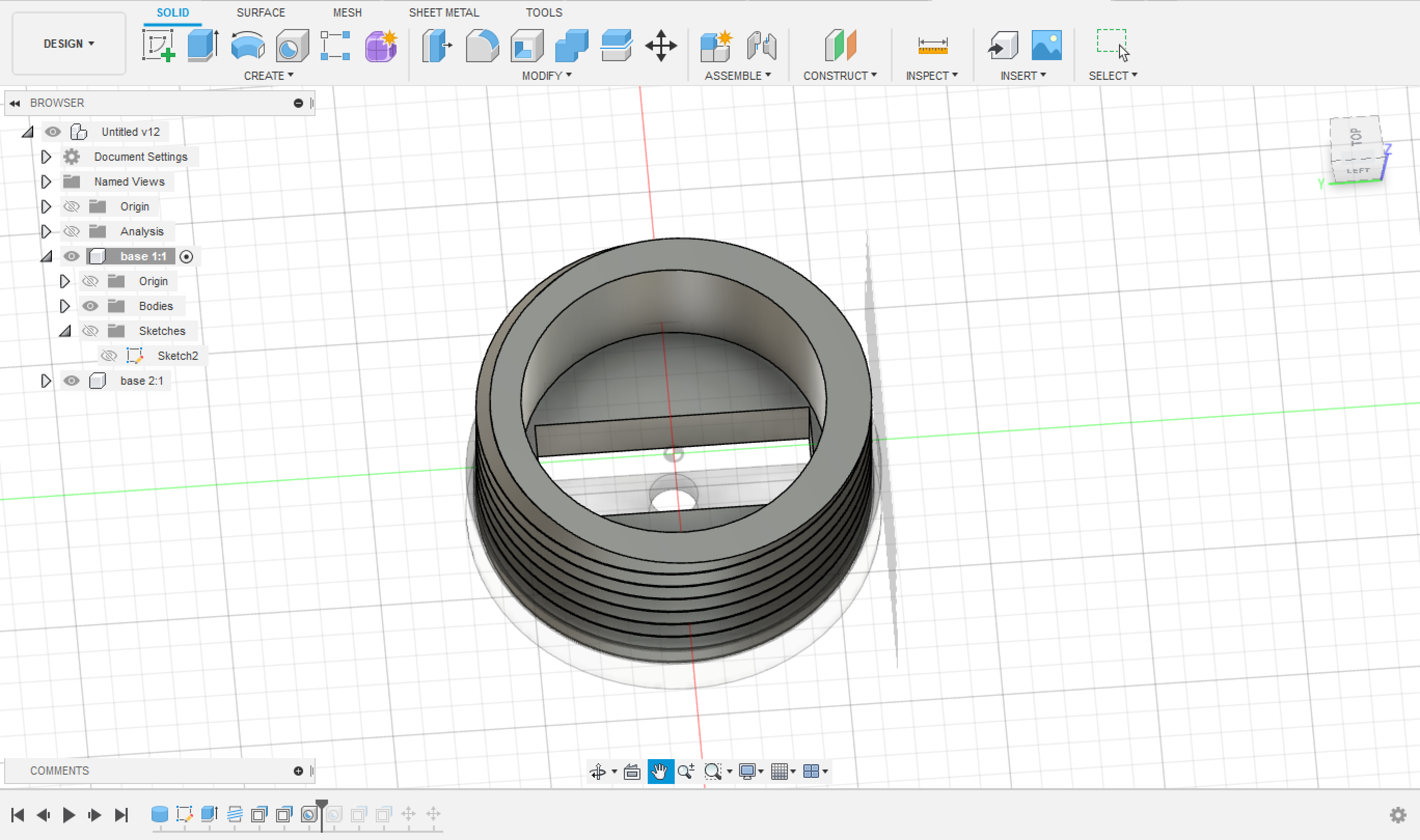
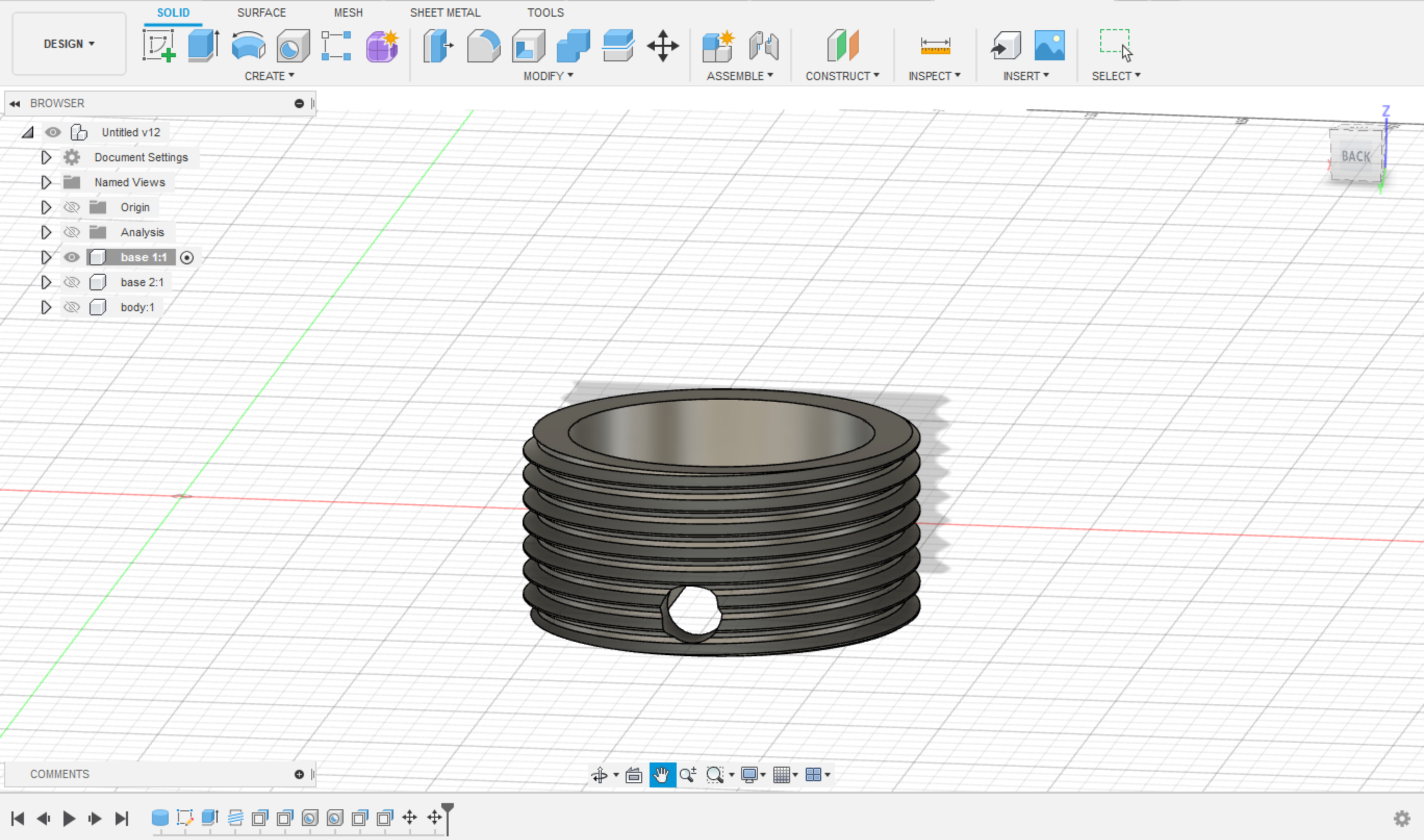
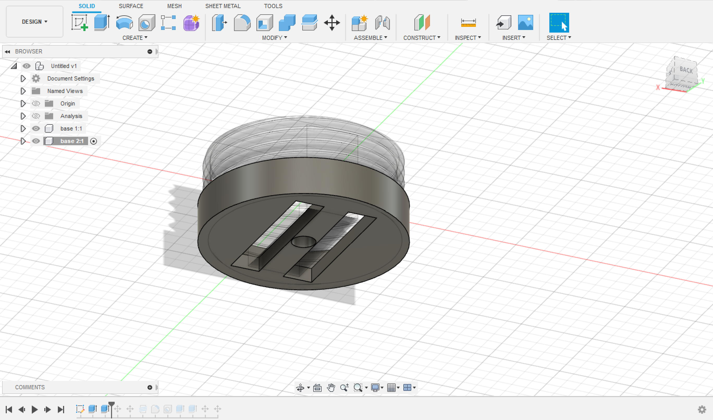
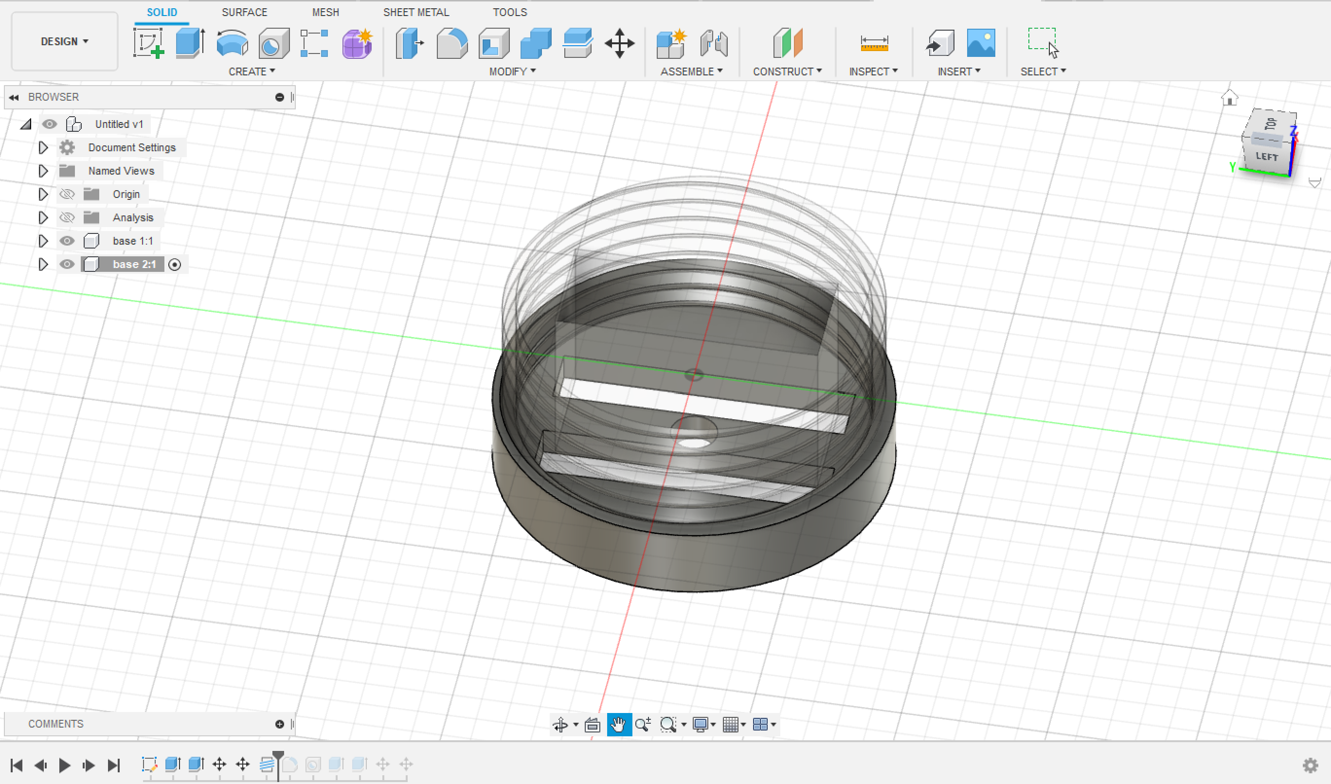
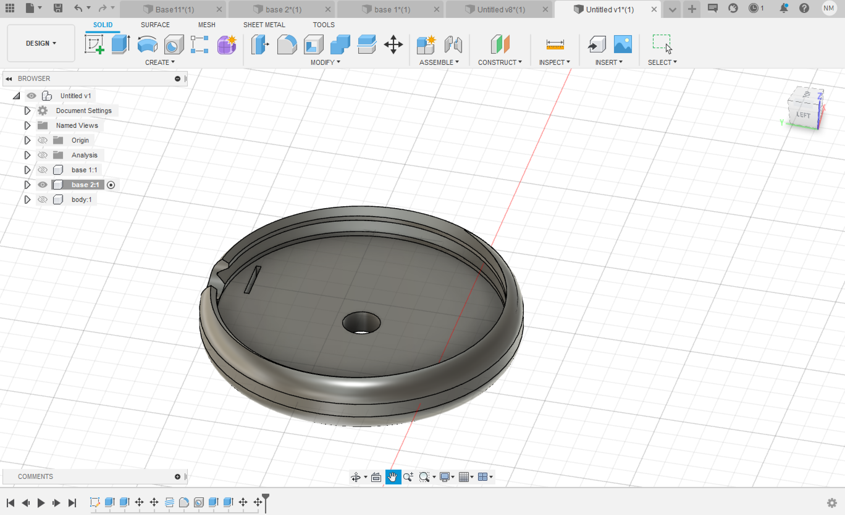
The final design of the 2nd Base is as seen:
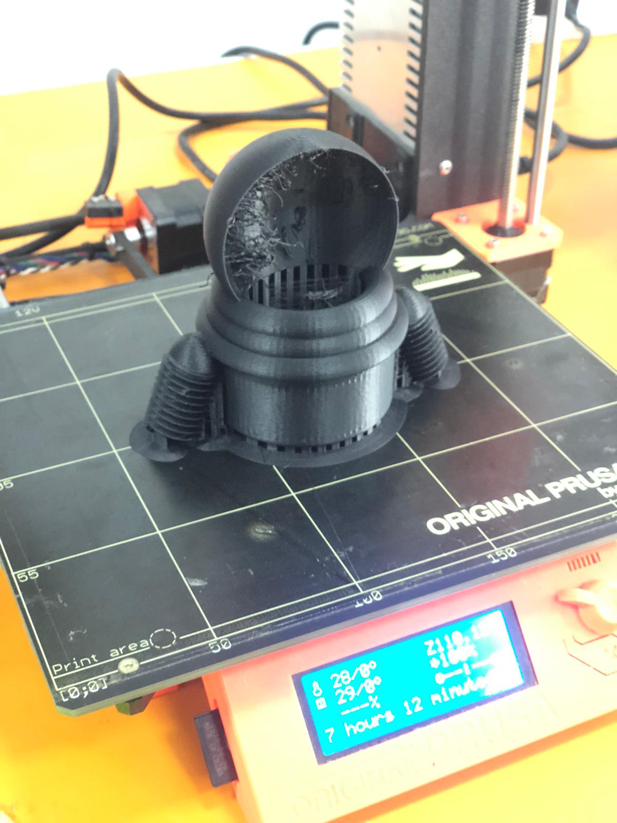
The 3 parts were 3D printed using Prusa i3 MK3S
I did the slicing in Ultimaker Cura; for further reading about the printer settings and how to 3D print Read This Page
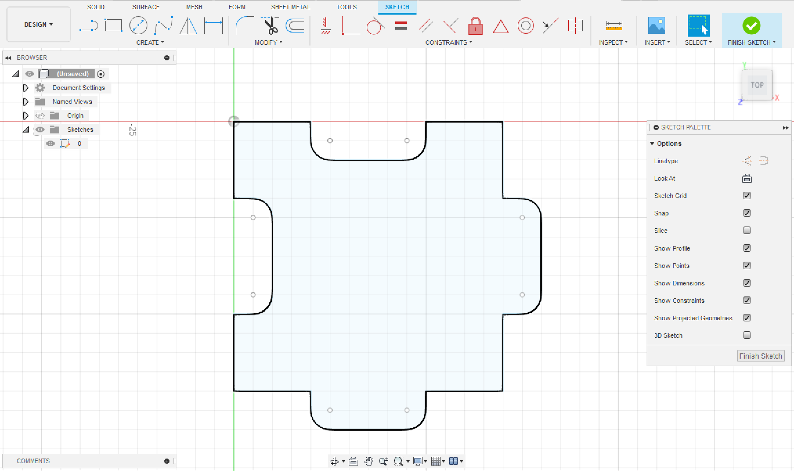
The design then was cut using a laser cutter, on different colored cardboards of height ~ 15mm.
To know more about the laser cutting process and the setting of the machine Read This Page
To download the file for the cards designs and the instructions see below.
Make sure to print the cards correctly as they are two-sided.
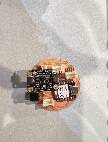
The electronic parts of this project are:
Wires for connections.
The electronic parts were connected as seen in the figure below:
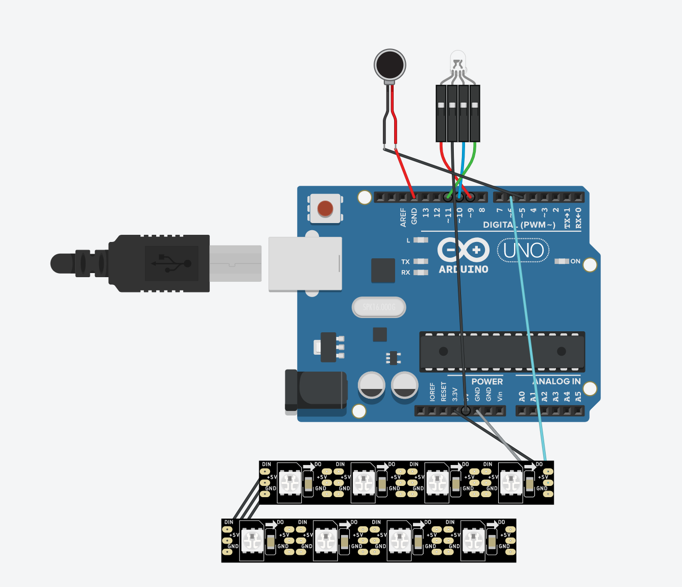
Simulation is done by TnkerCAD Note that Arduino Nano 33 BLE Sense was used in this project and not UNO.
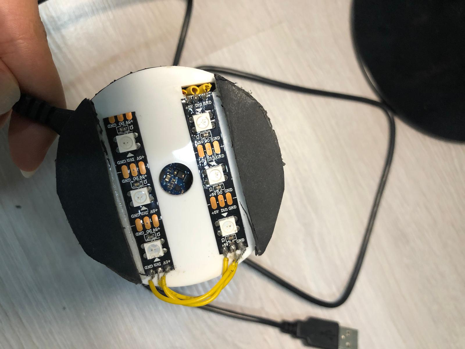
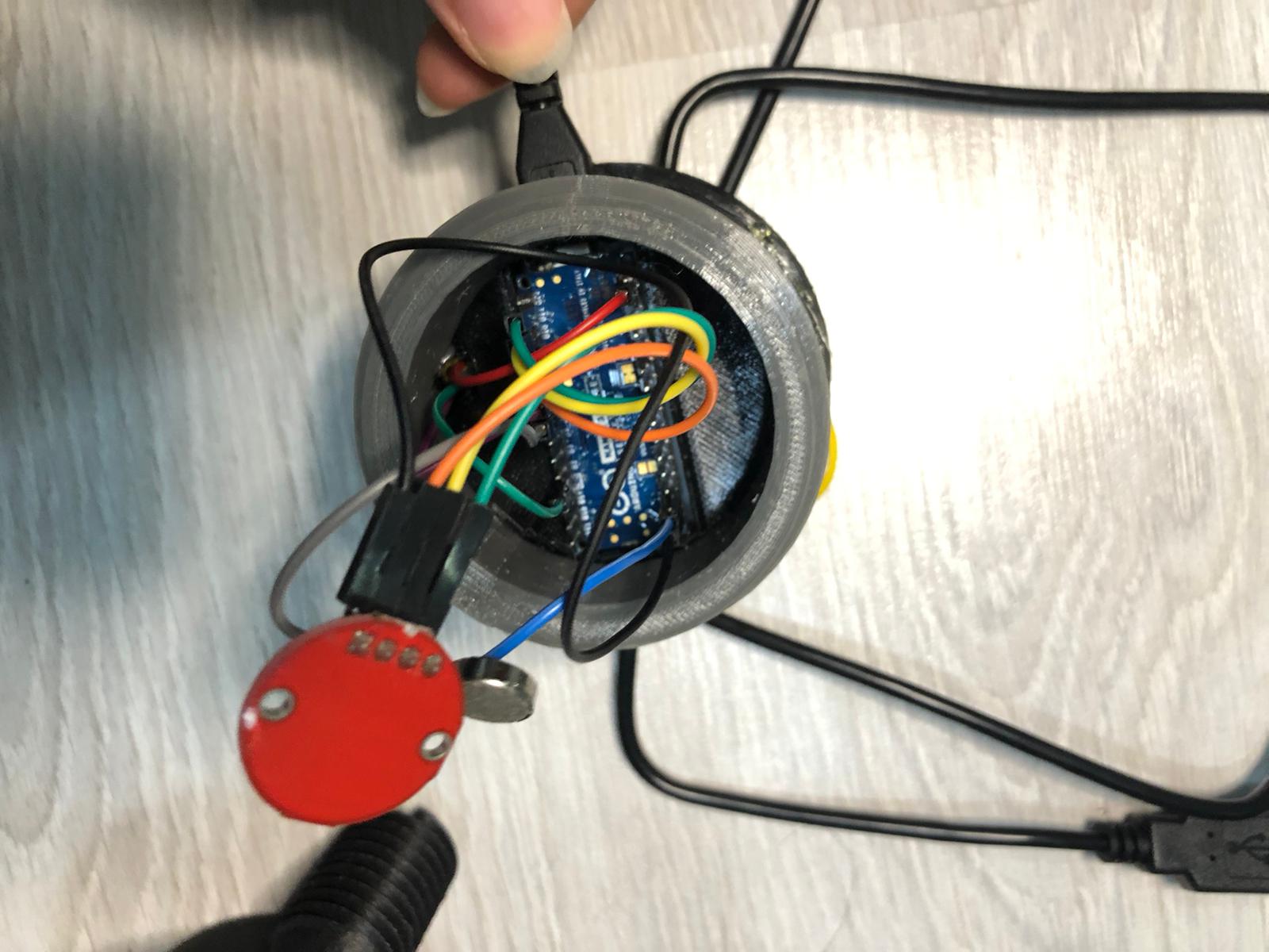
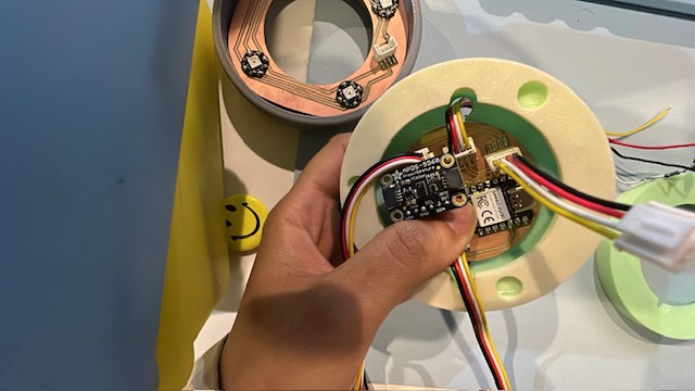
Now place the body part on top to cover all the electronics.
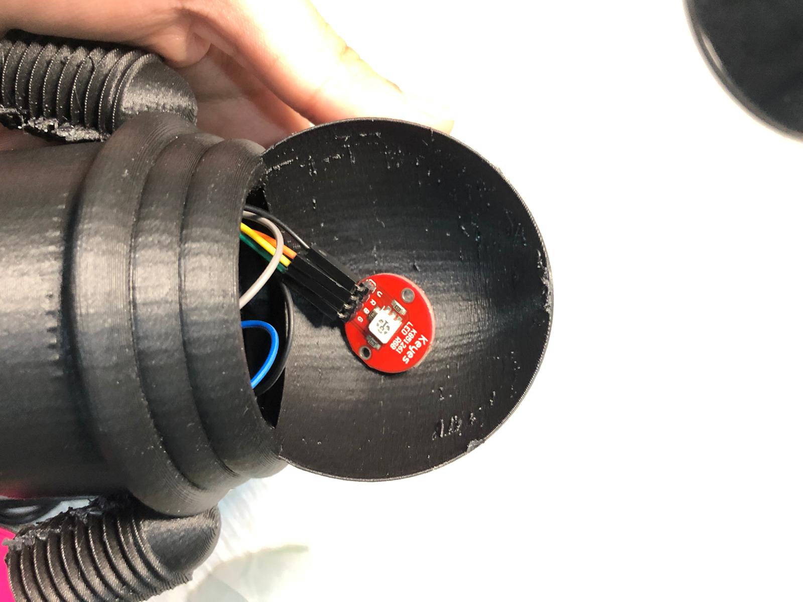
Make sure that the cords of the LED RGB are long enough for it to stick on the inside of the helmet of the astronaut.
The code of the game is as follows:
											// SENSOR LIBRARY
											#include <Arduino_APDS9960.h>

											//ADDRESSABLE RGB LED LIBRARY
											#include <Adafruit_NeoPixel.h>

											#ifdef __AVR__
											 #include <avr/power.h> // Required for 16 MHz Adafruit Trinket
											#endif
											// Which pin on the Arduino is connected to the NeoPixels?
											#define PIN        6 // LED PIN
											// How many NeoPixels are attached to the Arduino?
											#define NUMPIXELS 6 // Popular NeoPixel ring size
											Adafruit_NeoPixel pixels(NUMPIXELS, PIN, NEO_GRB + NEO_KHZ800);

											#define DELAYVAL 500 // Time (in milliseconds) to pause between pixels

											void setup() {

											#if defined(__AVR_ATtiny85__) && (F_CPU == 16000000)
											  clock_prescale_set(clock_div_1);
											#endif
											  // END of Trinket-specific code.

											  pixels.begin(); // INITIALIZE NeoPixel strip object (REQUIRED)

											  Serial.begin(9600);
											  while (!Serial);

											  if (!APDS.begin()) {
												Serial.println("Error initializing APDS-9960 sensor.");
											  }


												 pinMode(6, OUTPUT); //LED LIGHT (BASE)
												 pinMode(9, OUTPUT); // RED
												 pinMode(10, OUTPUT); //BLUE
												 pinMode(11, OUTPUT); //GREEN
												 pinMode(5, OUTPUT); //PUZZER


											}

											void loop() {


											  int r, g, b, a;
											  double rh, bh, gh, cmax, cmin, del, h, hf;

											  // read the color
											  APDS.readColor(r, g, b);

											  // print the values
											  Serial.print("r = ");
											  Serial.println(r);
											  Serial.print("g = ");
											  Serial.println(g);
											  Serial.print("b = ");
											  Serial.println(b);
											  Serial.println();

												// wait a bit before reading again
											  delay(500);


											  // LOWER LGB
											  pixels.clear(); // Set all pixel colors to 'off'

											  // The first NeoPixel in a strand is #0, second is 1, all the way up
											  // to the count of pixels minus one.
											  //for(int i=0; i<NUMPIXELS; i++) { // For each pixel...

												// pixels.Color() takes RGB values, from 0,0,0 up to 255,255,255

												pixels.setPixelColor(0, pixels.Color(255, 255, 255));
												pixels.setPixelColor(2,  pixels.Color(255, 255, 255));
												pixels.setPixelColor(3,  pixels.Color(255, 255, 255));
												pixels.setPixelColor(5,  pixels.Color(255, 255, 255));

												pixels.show();   // Send the updated pixel colors to the hardware.

												//delay(DELAYVAL); // Pause before next pass through loop
											  //}


											// SENSOR
											 // check if a color reading is available
											  while (! APDS.colorAvailable()) {
												delay(1);
											  }


											  //find new r,g,b,c,del
											  //rh=r/255;
											 // gh=g/255;
											  //bh=b/255;
											  cmax= max(r,g);
											  cmax= max(cmax,b);

											  cmin=min(r,g);
											  cmin= min(cmin,b);

											  del= (cmax-cmin);

											   // find HUE

											 if (r>g & r>b)
											  {h=60*((g-b)/del);}

											  if (g>r & g>b)
											  {h= 60*((b-r)/del+2);}

											  if (b>r & b>g)
											  {h=60*((r-g)/del+4);}

											if (h<0)
											{h=h+360;}

											  Serial.println();
											  Serial.println(h);
											  Serial.println();

											//GAME SETTINGS
											// depending on the value of h, the output led will change colors or the puzzer will turn on
											// REFRENCE FOR HUE VALUES FOR THE PIECES OF BLUE HOME GAME:

											while ( abs(h-hf) > 5.0)
											{
											// PINK
											if (h>220 & h <360)
											{
											  a= random(1,3);
											  }

											  //BLUE
											if (h<220 & h >210)
											{
												a= random(3,4);
											  }

											//BLACK
											if (h>180 & h <210)
											{
											  a=random(4,6);
											  }

											//GREEN
											if (h<180 & h >140)
											 {
											  a =random(1,3);
											  }

											  //OFFWHITE
											if (h<140 & h >40)
											{
											  a= random(4,8);
											  }

											 //YELLOW
											if (h<40 & h >0)
											{
											  a =random(3,5);
											  }

											//////////////////

											  if (a==1)
											{
											 digitalWrite(5, LOW ); // Turn the VIBRATING on
											 digitalWrite(9, LOW ); // RED
											 digitalWrite(10, LOW ); // BLUE
											 digitalWrite(11, HIGH ); //GREEN
											}

											if (a==2)

											{ digitalWrite(5, LOW ); // Turn the VIBRATING on
											 digitalWrite(9, HIGH ); // RED
											 digitalWrite(10, LOW ); // BLUE
											 digitalWrite(11, LOW ); //GREEN
											}

											if ( a==3)
											{
											 digitalWrite(5, LOW ); // Turn the VIBRATING on
											 digitalWrite(9, HIGH ); // RED
											 digitalWrite(10, LOW ); // BLUE
											 digitalWrite(11, LOW ); //GREEN
											 }


											if (a==4)
											{
											 digitalWrite(5, HIGH ); // Turn the VIBRATING on
											 digitalWrite(9, LOW ); // RED
											 digitalWrite(10, LOW ); // BLUE
											 digitalWrite(11, LOW ); //GREEN
											 }


											if (a==5)
											{
											 digitalWrite(5, LOW ); // Turn the VIBRATING on
											 digitalWrite(9, HIGH ); // RED
											 digitalWrite(10, HIGH ); // BLUE
											 digitalWrite(11, LOW ); //GREEN
											 }


											if (a==6)
											{
											 digitalWrite(5, HIGH ); // Turn the VIBRATING on
											 digitalWrite(9, LOW ); // RED
											 digitalWrite(10, HIGH ); // BLUE
											 digitalWrite(11, HIGH ); //GREEN
											 }


											if (a==7)
											{
											 digitalWrite(5, LOW ); // Turn the VIBRATING on
											 digitalWrite(9, LOW ); // RED
											 digitalWrite(10, HIGH ); // BLUE
											 digitalWrite(11, LOW ); //GREEN
											 }

											 hf = h;
											}


											  Serial.print("hf = ");
											  Serial.println(hf);
											  Serial.println();

											}
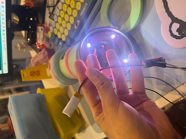
The code runs the LED in the base to light up the area under the piece so it is visible for the Arduino Built-In sensor, this LED is turned on through out the game.
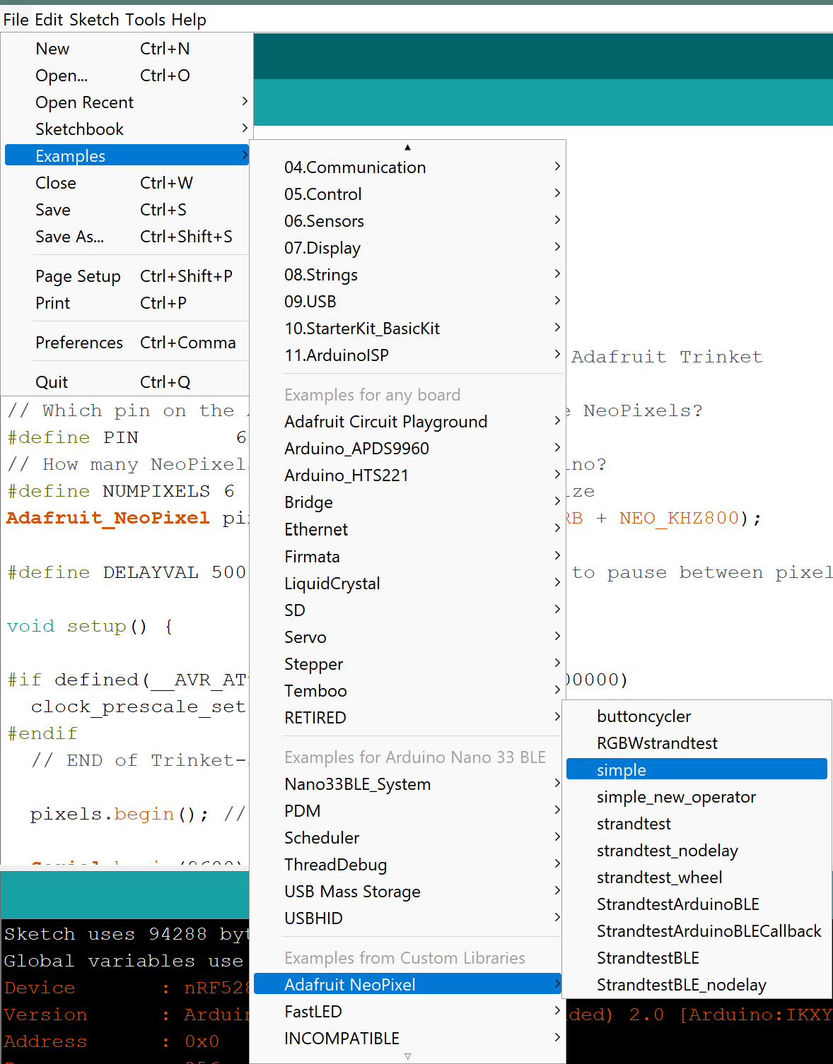
Note that the library for the addressable RGB LED strips is needed to be downloaded and included in the code. Adafruit NeoPixel Library
The Simple example helped me understand how to program the LED Strips, As they are vey bright I ended up using only 4 out of 6 LEDs.
The RGB sensor's library needs to be included in the code, the library is APDS9960.
The sensor reads values of RGB and then using equations convert them to a single value which is hue (h).
Then this value is compared to the previous calculated value of hue, and if there is a difference (meaning the piece has moved) then the piece will randomly react depending on the color it sensed.
The reaction is the change of the head's color (White/Red/Pink/Cyan/Yellow/Green) or a vibration.
A useful page to understand how RGB sensor works here
// NeoPixel Ring simple sketch (c) 2013 Shae Erisson
											// Released under the GPLv3 license to match the rest of the
											// Adafruit NeoPixel library

											#include <Adafruit_NeoPixel.h>
											#ifdef __AVR__
											 #include <avr/power.h> // Required for 16 MHz Adafruit Trinket
											#endif

											// Which pin on the Arduino is connected to the NeoPixels?
											#define PIN        6 // On Trinket or Gemma, suggest changing this to 1

											// How many NeoPixels are attached to the Arduino?
											#define NUMPIXELS 16 // Popular NeoPixel ring size

											// When setting up the NeoPixel library, we tell it how many pixels,
											// and which pin to use to send signals. Note that for older NeoPixel
											// strips you might need to change the third parameter -- see the
											// strandtest example for more information on possible values.
											Adafruit_NeoPixel pixels(NUMPIXELS, PIN, NEO_GRB + NEO_KHZ800);

											#define DELAYVAL 500 // Time (in milliseconds) to pause between pixels

											void setup() {
											  // These lines are specifically to support the Adafruit Trinket 5V 16 MHz.
											  // Any other board, you can remove this part (but no harm leaving it):
											#if defined(__AVR_ATtiny85__) && (F_CPU == 16000000)
											  clock_prescale_set(clock_div_1);
											#endif
											  // END of Trinket-specific code.

											  pixels.begin(); // INITIALIZE NeoPixel strip object (REQUIRED)
											}

											void loop() {
											  pixels.clear(); // Set all pixel colors to 'off'

											  // The first NeoPixel in a strand is #0, second is 1, all the way up
											  // to the count of pixels minus one.
											  for(int i=0; i<NUMPIXELS; i++) { // For each pixel...

												// pixels.Color() takes RGB values, from 0,0,0 up to 255,255,255
												// Here we're using a moderately bright green color:
												pixels.setPixelColor(i, pixels.Color(0, 150, 0));

												pixels.show();   // Send the updated pixel colors to the hardware.

												delay(DELAYVAL); // Pause before next pass through loop
											  }
											}
/*
											  APDS-9960 - Color Sensor

											  This example reads color data from the on-board APDS-9960 sensor of the
											  Nano 33 BLE Sense and prints the color RGB (red, green, blue) values
											  to the Serial Monitor once a second.

											  The circuit:
											  - Arduino Nano 33 BLE Sense

											  This example code is in the public domain.
											*/

											#include <Arduino_APDS9960.h>

											void setup() {
											  Serial.begin(9600);
											  while (!Serial);

											  if (!APDS.begin()) {
												Serial.println("Error initializing APDS-9960 sensor.");
											  }
											}

											void loop() {
											  // check if a color reading is available
											  while (! APDS.colorAvailable()) {
												delay(5);
											  }
											  int r, g, b;

											  // read the color
											  APDS.readColor(r, g, b);

											  // print the values
											  Serial.print("r = ");
											  Serial.println(r);
											  Serial.print("g = ");
											  Serial.println(g);
											  Serial.print("b = ");
											  Serial.println(b);
											  Serial.println();

											  // wait a bit before reading again
											  delay(1000);
											}
											// SENSOR LIBRARY
											#include <Arduino_APDS9960.h>

											//ADDRESSABLE RGB LED LIBRARY
											#include <Adafruit_NeoPixel.h>

											#ifdef __AVR__
											 #include <avr/power.h> // Required for 16 MHz Adafruit Trinket
											#endif
											// Which pin on the Arduino is connected to the NeoPixels?
											#define PIN        6 // LED PIN
											// How many NeoPixels are attached to the Arduino?
											#define NUMPIXELS 6 // Popular NeoPixel ring size
											Adafruit_NeoPixel pixels(NUMPIXELS, PIN, NEO_GRB + NEO_KHZ800);

											#define DELAYVAL 500 // Time (in milliseconds) to pause between pixels

											void setup() {

											#if defined(__AVR_ATtiny85__) && (F_CPU == 16000000)
											  clock_prescale_set(clock_div_1);
											#endif
											  // END of Trinket-specific code.

											  pixels.begin(); // INITIALIZE NeoPixel strip object (REQUIRED)

											  Serial.begin(9600);
											  while (!Serial);

											  if (!APDS.begin()) {
												Serial.println("Error initializing APDS-9960 sensor.");
											  }


												 pinMode(6, OUTPUT); //LED LIGHT (BASE)
												 pinMode(9, OUTPUT); // RED
												 pinMode(10, OUTPUT); //BLUE
												 pinMode(11, OUTPUT); //GREEN
												 pinMode(5, OUTPUT); //PUZZER


											}

											void loop() {


											  int r, g, b;
											  double rh, bh, gh, cmax, cmin, del, h;

											  // read the color
											  APDS.readColor(r, g, b);

											  // print the values
											  Serial.print("r = ");
											  Serial.println(r);
											  Serial.print("g = ");
											  Serial.println(g);
											  Serial.print("b = ");
											  Serial.println(b);
											  Serial.println();

												// wait a bit before reading again
											  delay(500);


											  // LOWER LGB
											  pixels.clear(); // Set all pixel colors to 'off'

											  // The first NeoPixel in a strand is #0, second is 1, all the way up
											  // to the count of pixels minus one.
											  //for(int i=0; i<NUMPIXELS; i++) { // For each pixel...

												// pixels.Color() takes RGB values, from 0,0,0 up to 255,255,255

												pixels.setPixelColor(0, pixels.Color(255, 255, 255));
												pixels.setPixelColor(2,  pixels.Color(255, 255, 255));
												pixels.setPixelColor(3,  pixels.Color(255, 255, 255));
												pixels.setPixelColor(5,  pixels.Color(255, 255, 255));

												pixels.show();   // Send the updated pixel colors to the hardware.

												//delay(DELAYVAL); // Pause before next pass through loop
											  //}


											// SENSOR
											 // check if a color reading is available
											  while (! APDS.colorAvailable()) {
												delay(1);
											  }


											  //find new r,g,b,c,del
											  //rh=r/255;
											 // gh=g/255;
											  //bh=b/255;
											  cmax= max(r,g);
											  cmax= max(cmax,b);

											  cmin=min(r,g);
											  cmin= min(cmin,b);

											  del= (cmax-cmin);

											   // find HUE

											 if (r>g & r>b)
											  {h=60*((g-b)/del);}

											  if (g>r & g>b)
											  {h= 60*((b-r)/del+2);}

											  if (b>r & b>g)
											  {h=60*((r-g)/del+4);}

											if (h<0)
											{h=h+360;}

											  Serial.println();
											  Serial.println(h);
											  Serial.println();


											//GAME SETTINGS
											// depending on the value of h, the output led will change colors or the puzzer will turn on
											// REFRENCE FOR HUE VALUES FOR THE PIECES OF BLUE HOME GAME:


											// PINK
											if (h>220 & h <360)
											{
											 digitalWrite(5, LOW ); // Turn the VIBRATING on
											 digitalWrite(9, LOW ); // RED
											 digitalWrite(10, LOW ); // BLUE
											 digitalWrite(11, HIGH ); //GREEN
											 }

											//BLUE
											if (h<220 & h >210)
											{
											 digitalWrite(5, LOW ); // Turn the VIBRATING on
											 digitalWrite(9, HIGH ); // RED
											 digitalWrite(10, LOW ); // BLUE
											 digitalWrite(11, LOW ); //GREEN
											 }


											//BLACK
											if (h>180 & h <210)
											{
											 digitalWrite(5, HIGH ); // Turn the VIBRATING on
											 digitalWrite(9, LOW ); // RED
											 digitalWrite(10, LOW ); // BLUE
											 digitalWrite(11, LOW ); //GREEN
											 }

											//GREEN
											if (h<180 & h >140)
											{
											 digitalWrite(5, LOW ); // Turn the VIBRATING on
											 digitalWrite(9, HIGH ); // RED
											 digitalWrite(10, HIGH ); // BLUE
											 digitalWrite(11, LOW ); //GREEN
											 }


											//OFFWHITE
											if (h<140 & h >40)
											{
											 digitalWrite(5, HIGH ); // Turn the VIBRATING on
											 digitalWrite(9, LOW ); // RED
											 digitalWrite(10, HIGH ); // BLUE
											 digitalWrite(11, HIGH ); //GREEN
											 }


											 //YELLOW
											if (h<40 & h >0)
											{
											 digitalWrite(5, LOW ); // Turn the VIBRATING on
											 digitalWrite(9, LOW ); // RED
											 digitalWrite(10, HIGH ); // BLUE
											 digitalWrite(11, LOW ); //GREEN
											 }

											}
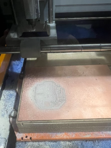
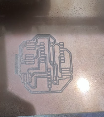
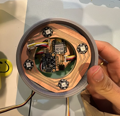
Moving from the Alpha version, we developed a modified version with fully customized electronics to improve integration, accuracy, and usability.
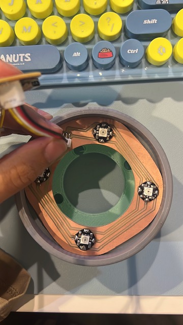
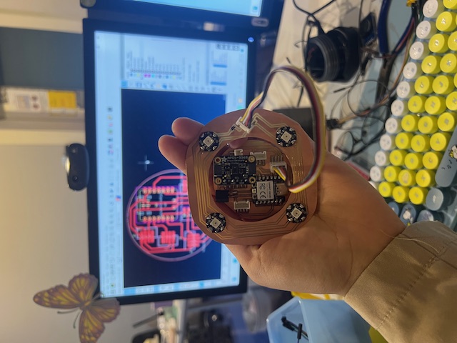
This upgraded electronics design makes EduTile more robust, compact, and user-friendly, while maintaining all interactive features of the game.
The PCBs design were made in KiCAD.
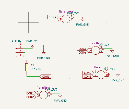
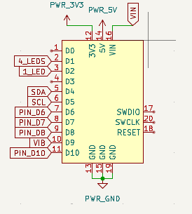

 Download KiCAD Project
This final version of EduTile integrates all custom electronics and interactive features into a single, compact system. The main improvements include:
The code combines the APDS9960 sensor, NeoPixel LEDs, vibration motor, and SSD1306 OLED display to create a rich, interactive experience for learners.
#include <Arduino_APDS9960.h>
#include <Adafruit_NeoPixel.h>
#include <Wire.h>
#include <Adafruit_SSD1306.h>
#define WHITE_LED_PIN 27
#define COLOR_LED_PIN 28
#define VIBRATOR_PIN 4
#define NUM_WHITE_LEDS 4
Adafruit_NeoPixel whiteLEDs(NUM_WHITE_LEDS, WHITE_LED_PIN, NEO_GRB + NEO_KHZ800);
Adafruit_NeoPixel colorLED(1, COLOR_LED_PIN, NEO_GRB + NEO_KHZ800);
#define SCREEN_WIDTH 128
#define SCREEN_HEIGHT 64
Adafruit_SSD1306 display(SCREEN_WIDTH, SCREEN_HEIGHT, &Wire, -1);
enum GameState {
WAIT_FOR_PROXIMITY,
SHOW_DICE_RESULT,
WAIT_FOR_SECOND_PROXIMITY,
SHOW_COLOR_RESULT
};
GameState state = WAIT_FOR_PROXIMITY;
unsigned long lastActionTime = 0;
int diceSteps = 0;
uint32_t Wheel(byte WheelPos) {
WheelPos = 255 - WheelPos;
if (WheelPos < 85) {
return colorLED.Color(255 - WheelPos * 3, 0, WheelPos * 3);
}
if (WheelPos < 170) {
WheelPos -= 85;
return colorLED.Color(0, WheelPos * 3, 255 - WheelPos * 3);
}
WheelPos -= 170;
return colorLED.Color(WheelPos * 3, 255 - WheelPos * 3, 0);
}
void displayEduTile() {
display.clearDisplay();
display.setTextSize(3);
display.setTextColor(SSD1306_WHITE);
int16_t x1, y1;
uint16_t w, h;
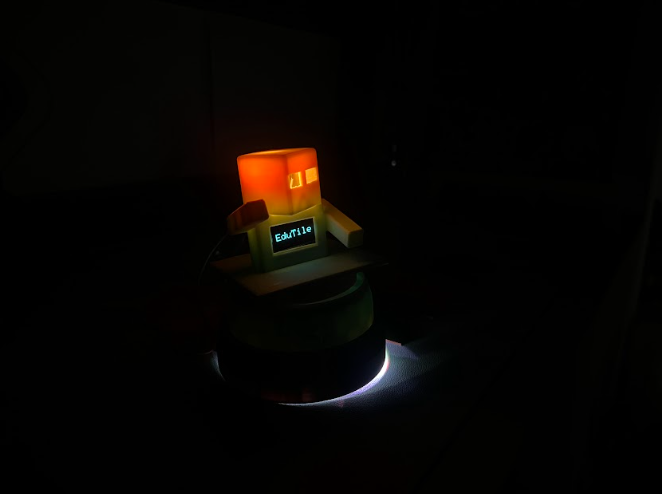
display.getTextBounds("EduTile", 0, 0, &x1, &y1, &w, &h);
display.setCursor((SCREEN_WIDTH - w) / 2, (SCREEN_HEIGHT - h) / 2);
display.println("EduTile");
display.display();
}
void displayColorMessage(const char* mainWord, const char* instruction) {
display.clearDisplay();
// Big main word at the top
display.setTextSize(3);
display.setTextColor(SSD1306_WHITE);
int16_t x1, y1;
uint16_t w, h;
display.getTextBounds(mainWord, 0, 0, &x1, &y1, &w, &h);
display.setCursor((SCREEN_WIDTH - w) / 2, 0);
display.println(mainWord);
// Smaller instruction centered vertically below the main word
display.setTextSize(1);
display.getTextBounds(instruction, 0, 0, &x1, &y1, &w, &h);
int cursorY = 40 + (24 - h) / 2; // Roughly centered below main word (24 px height for size 3)
display.setCursor((SCREEN_WIDTH - w) / 2, cursorY);
display.println(instruction);
display.display();
}
void setup() {
Serial.begin(9600);
whiteLEDs.begin();
whiteLEDs.show();
colorLED.begin();
colorLED.show();
for (int i = 0; i < NUM_WHITE_LEDS; i++) {
whiteLEDs.setPixelColor(i, whiteLEDs.Color(255, 255, 255));
}
whiteLEDs.show();
pinMode(VIBRATOR_PIN, OUTPUT);
digitalWrite(VIBRATOR_PIN, LOW);
if (!display.begin(SSD1306_SWITCHCAPVCC, 0x3C)) {
while (true);
}
displayEduTile();
if (!APDS.begin()) {
while (true);
}
}
void loop() {
static uint8_t colorPos = 0;
// Rainbow LED animation
colorLED.setPixelColor(0, Wheel(colorPos));
colorLED.show();
colorPos++;
if (colorPos >= 256) colorPos = 0;
switch (state) {
case WAIT_FOR_PROXIMITY:
if (APDS.proximityAvailable()) {
uint8_t proximity = APDS.readProximity();
if (proximity > 20) { // Hand detected, roll dice
diceSteps = random(1, 7); // Dice roll 1-6
display.clearDisplay();
display.setTextSize(2);
display.setTextColor(SSD1306_WHITE);
display.setCursor(0, 0);
display.println("Move");
display.setCursor(0, 30);
display.setTextSize(3);
display.print(diceSteps);
display.println(" steps");
display.display();
uint32_t ledColor = colorLED.Color(255, 255, 255);
if (diceSteps <= 2) ledColor = colorLED.Color(255, 0, 0);
else if (diceSteps <= 4) ledColor = colorLED.Color(0, 255, 0);
else ledColor = colorLED.Color(0, 0, 255);
colorLED.setPixelColor(0, ledColor);
colorLED.show();
digitalWrite(VIBRATOR_PIN, HIGH);
delay(500);
digitalWrite(VIBRATOR_PIN, LOW);
lastActionTime = millis();
state = SHOW_DICE_RESULT;
}
}
break;
case SHOW_DICE_RESULT:
if (millis() - lastActionTime > 7000) { // 7 seconds display time
displayEduTile();
state = WAIT_FOR_SECOND_PROXIMITY;
}
break;
case WAIT_FOR_SECOND_PROXIMITY:
if (APDS.proximityAvailable()) {
uint8_t proximity = APDS.readProximity();
if (proximity > 20) { // Hand detected to read color
if (APDS.colorAvailable()) {
int r, g, b;
APDS.readColor(r, g, b);
float rf = r / 255.0;
float gf = g / 255.0;
float bf = b / 255.0;
float cmax = max(rf, max(gf, bf));
float cmin = min(rf, min(gf, bf));
float delta = cmax - cmin;
float h = 0;
if (delta == 0) h = 0;
else if (cmax == rf) h = 60 * fmod(((gf - bf) / delta), 6);
else if (cmax == gf) h = 60 * (((bf - rf) / delta) + 2);
else if (cmax == bf) h = 60 * (((rf - gf) / delta) + 4);
if (h < 0) h += 360;
uint32_t ledColor = colorLED.Color(0, 0, 0);
const char* mainWord = "";
const char* instruction = "";
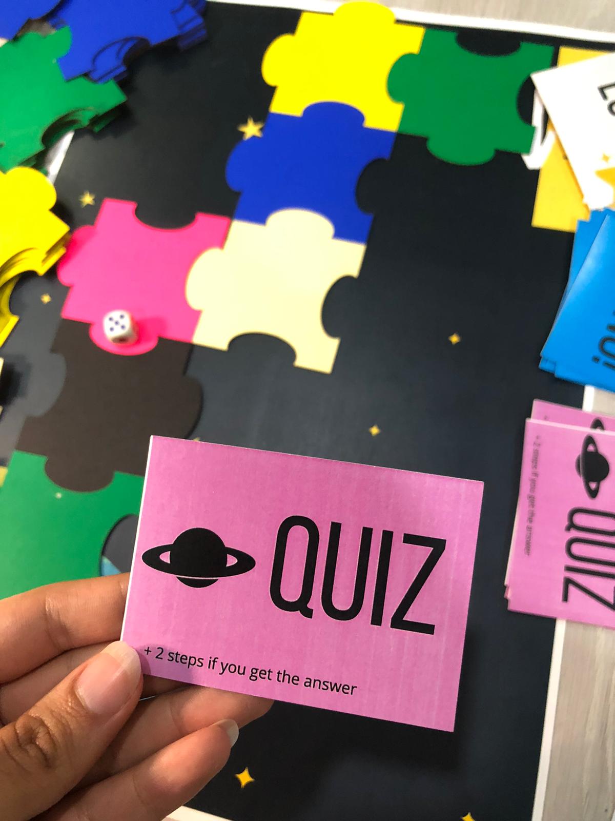
if (h > 220 && h < 360) {
ledColor = colorLED.Color(255, 0, 255); // Pink
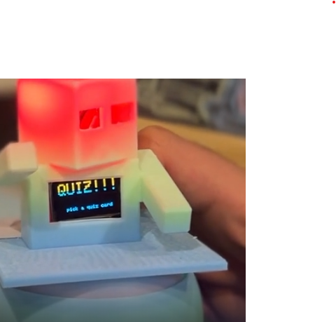
mainWord = "QUIZ!!!";
instruction = "pick a quiz card";
}
else if (h < 220 && h > 210) {
ledColor = colorLED.Color(0, 0, 255); // Blue
mainWord = "RING";
instruction = "pick a ring card";
}
else if (h > 180 && h < 210) {
ledColor = colorLED.Color(0, 0, 0); // Black (off)
mainWord = "BLACK";
instruction = "No card";
}
else if (h < 180 && h > 140) {
ledColor = colorLED.Color(0, 255, 0); // Green
mainWord = "MOVE";
instruction = "2 steps forward";
}
else if (h < 140 && h > 40) {
ledColor = colorLED.Color(255, 255, 255); // Offwhite
mainWord = "OFFWHITE";
instruction = "No action";
}
else if (h < 40 && h > 0) {
ledColor = colorLED.Color(255, 255, 0); // Yellow
mainWord = "LUCK!!";
instruction = "pick a luck card";
}
else {
ledColor = colorLED.Color(0, 0, 0);
mainWord = "UNKNOWN";
instruction = "";
}
colorLED.setPixelColor(0, ledColor);
colorLED.show();
displayColorMessage(mainWord, instruction);
digitalWrite(VIBRATOR_PIN, HIGH);
delay(500);
digitalWrite(VIBRATOR_PIN, LOW);
lastActionTime = millis();
state = SHOW_COLOR_RESULT;
}
}
}
break;
case SHOW_COLOR_RESULT:
if (millis() - lastActionTime > 7000) { // 7 seconds display time
displayEduTile();
state = WAIT_FOR_PROXIMITY;
}
break;
}
delay(50);
}
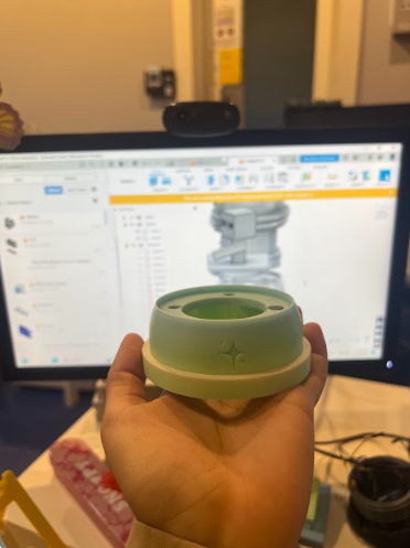
The design of EduTile focuses on modularity, ease of assembly, and integration of electronics. It consists of two main bases and a detachable character piece.

Check out my featured lesson plan on Scopes DF, the 1st place winner in May 2023 contest
Learn how to make an interactive game that can be suitable for whatever lesson you have.
A workshop presented in Fab Educators Summit January 2024, with Haitham Alnaser
Transform your regular lesson plan canvas into a gamified lesson.
Check out my bulk properties of matter course at BAIMS. for PHYCS209 [University of Bahrain].
Note: Delivery language is in Arabic, and material is specific to what is taught in UoB.