


git
Git is a distributed version control system that tracks changes in any set of computer files.
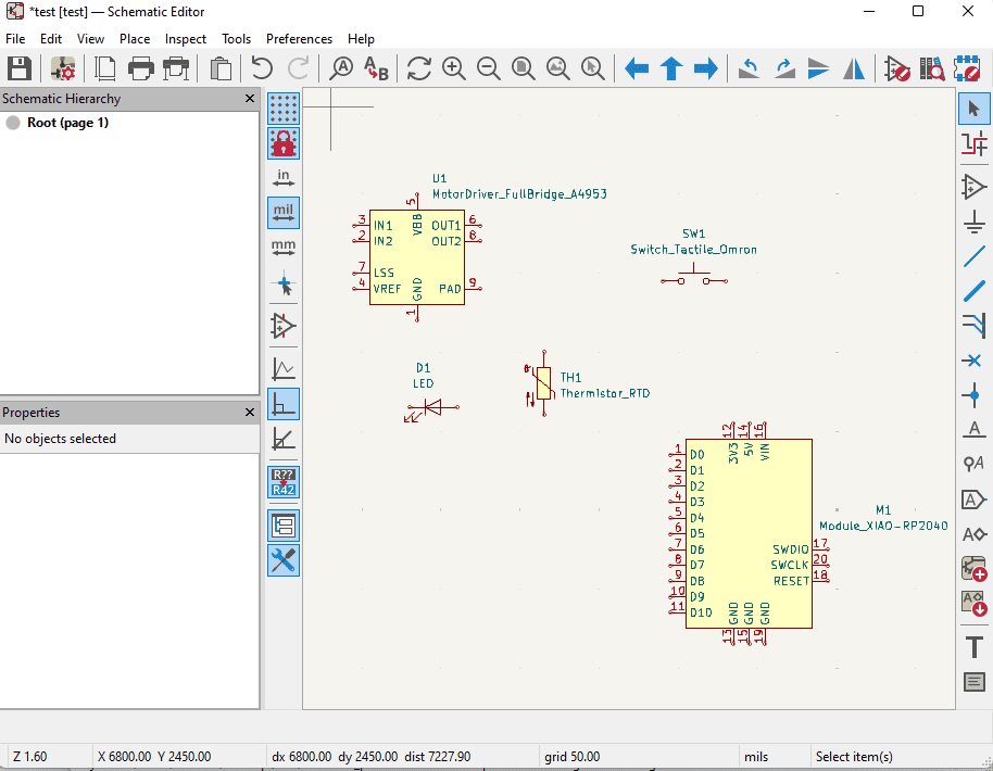
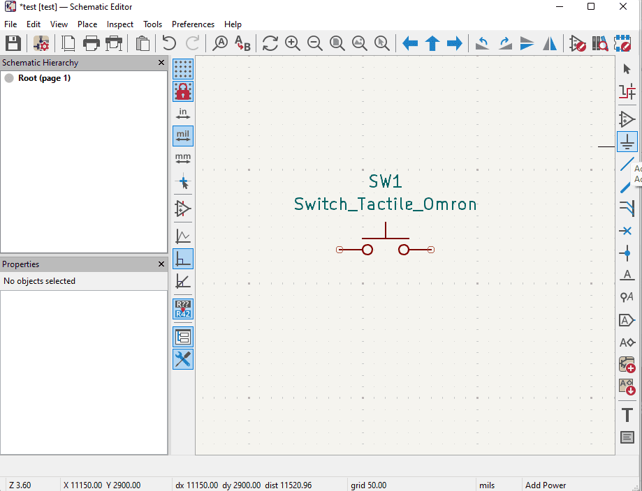
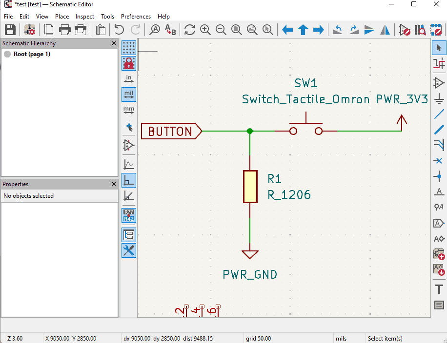
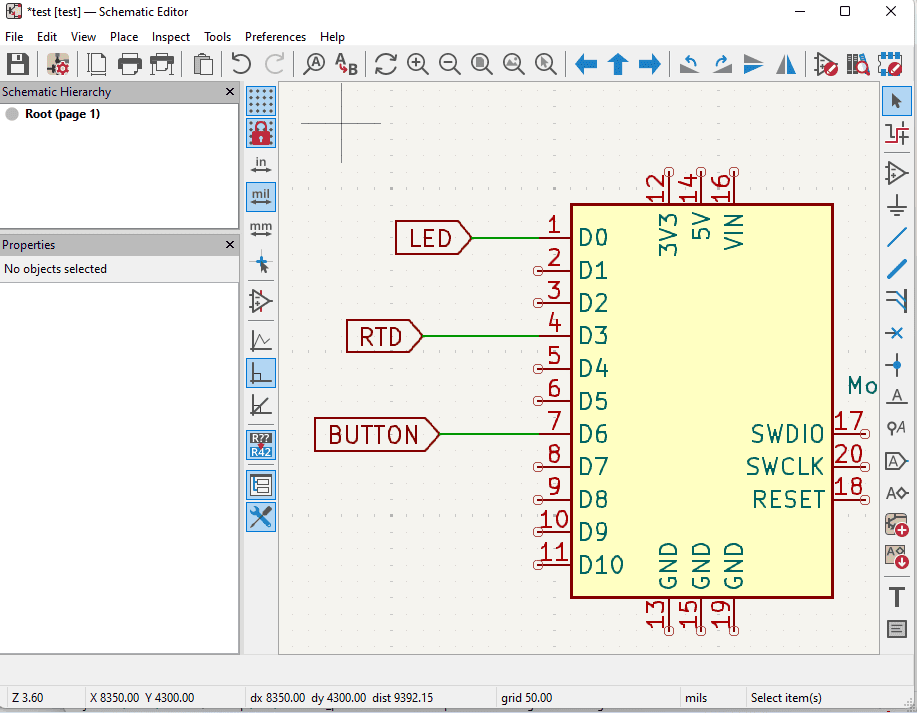
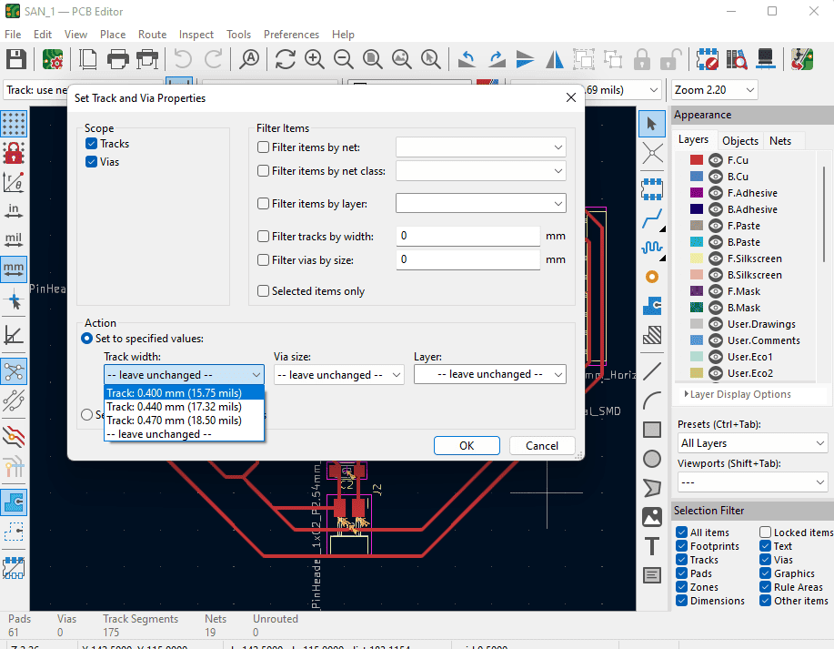
This week I designed my first ever PCB, with different inputs & outputs.
Git is a distributed version control system that tracks changes in any set of computer files.

This week, I designed my first ever PCB. To do that, it recuired some researc on what a PCB is, what components I should add, and how to connect them using some physics equations.
What is a PCB?
A Printed Circuit Board (PCB) is a board used to mechanically support and electrically connect electronic components using conductive tracks, pads, and other features etched from copper sheets laminated onto a non-conductive substrate. It is widely used in almost all electronic devices to organize circuits efficiently and reliably.
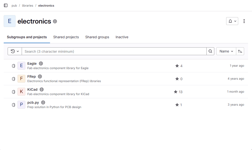
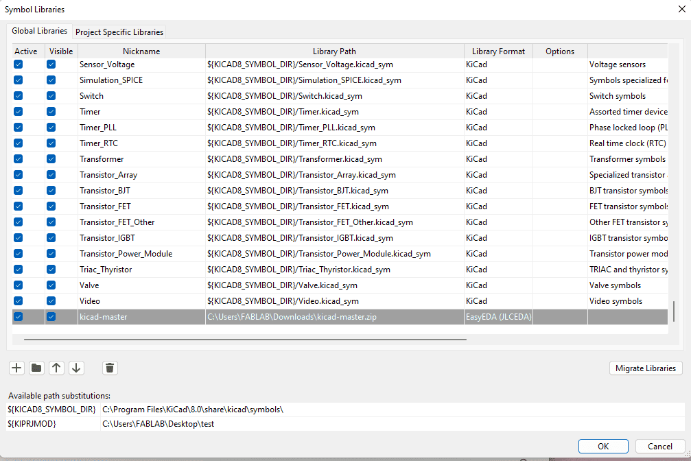
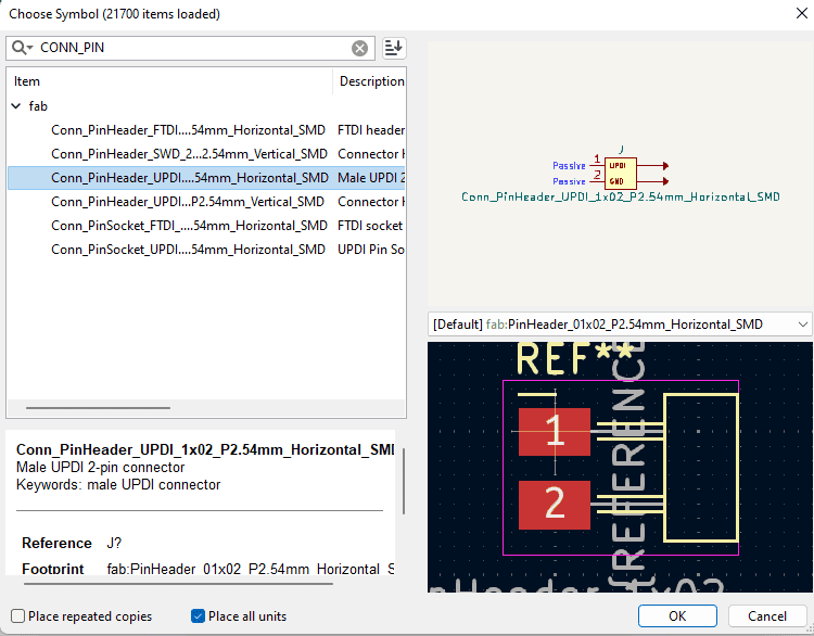
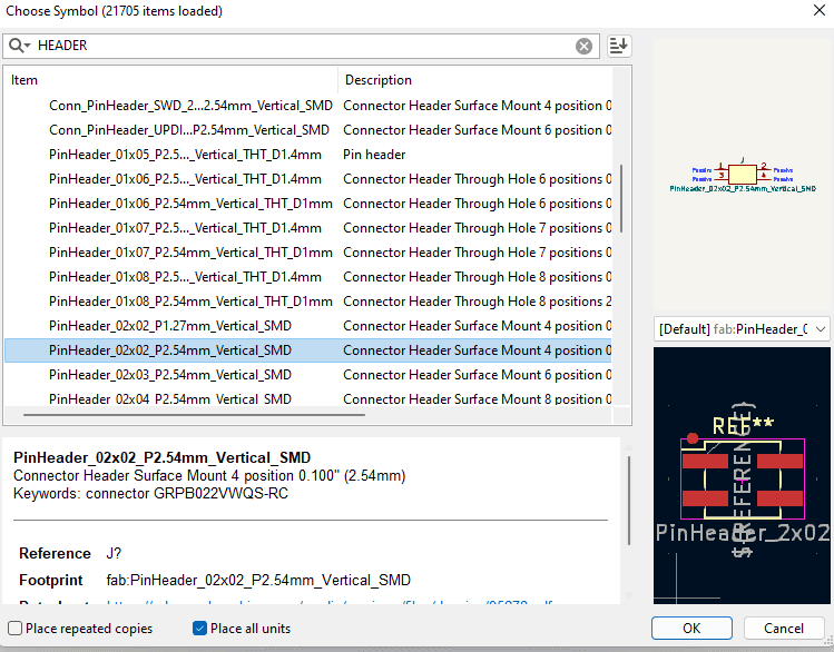
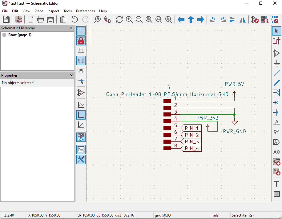
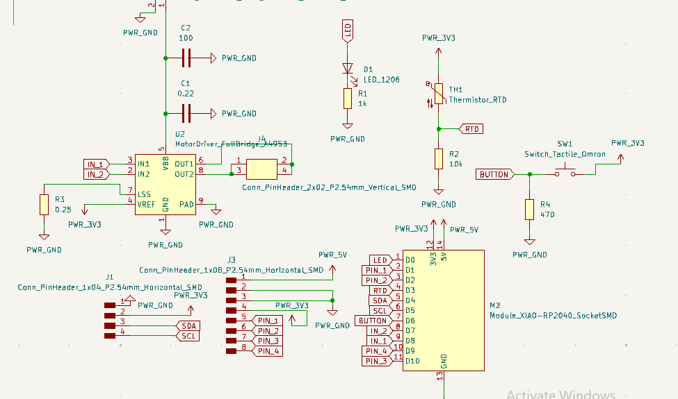
For this PCB, I tried to make it with many pin outs that will be useful. When it come to the electronics components, I looked for what is available in our Fab Lab storage, and I found the following:
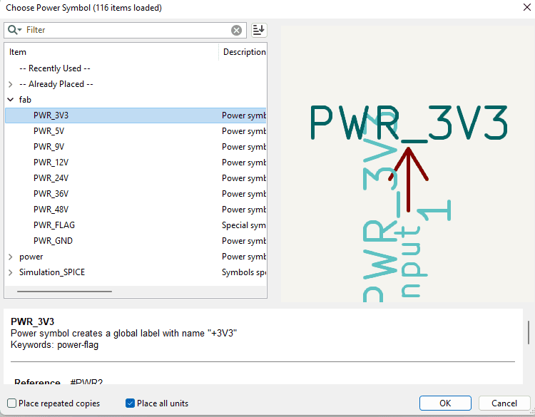
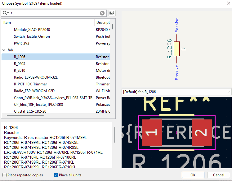
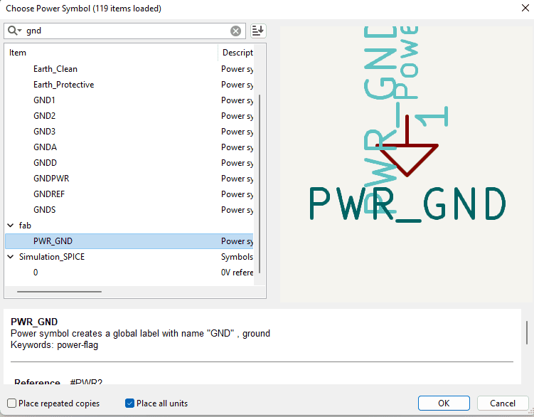
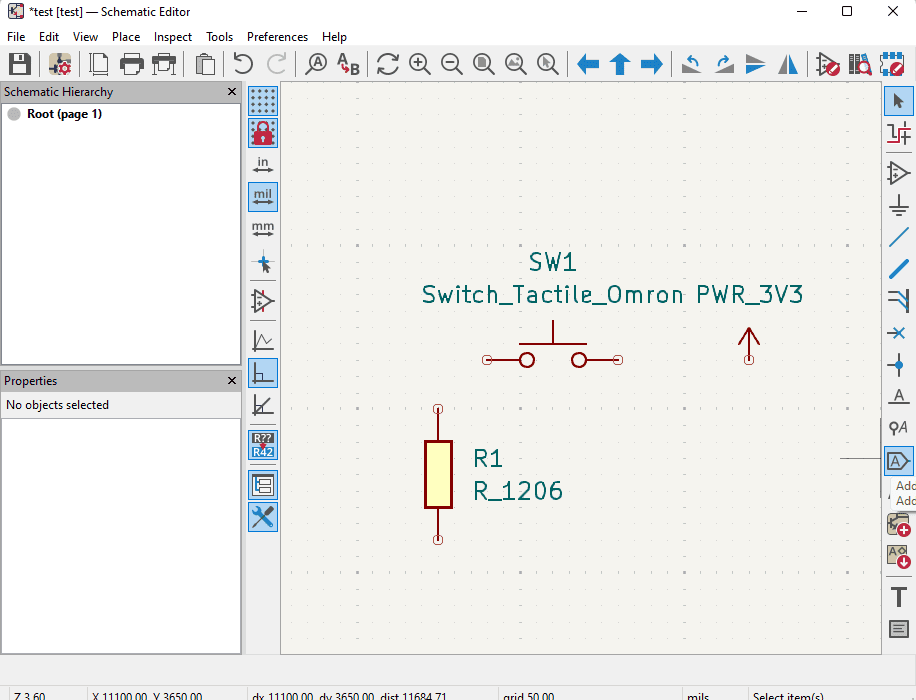
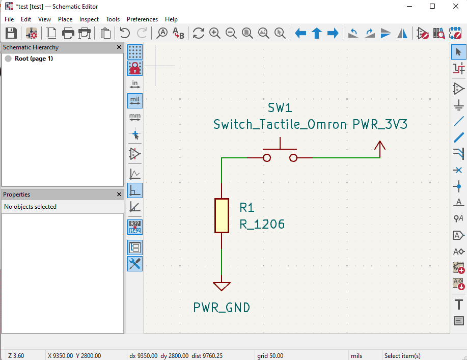
Now it is time to research each of them, the recuired added components to them [resistors & capacipors] so I can work on the schematics. Note that all the components I am planning to use are SMD. The values here are from my research on what is recuired for each of those components.
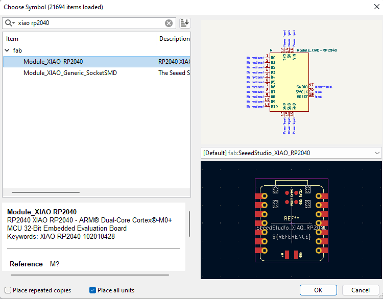
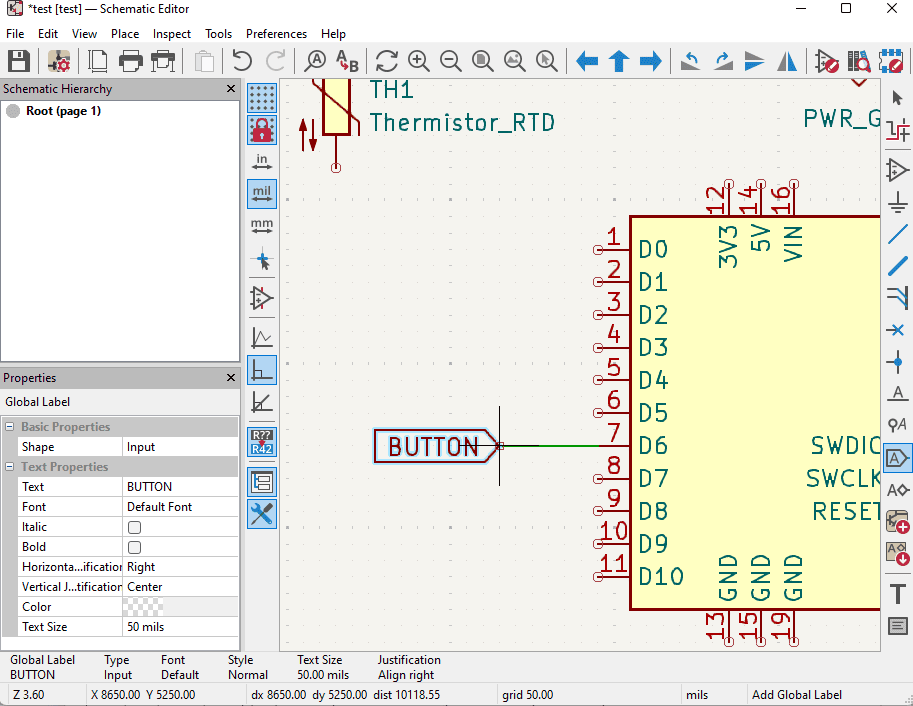
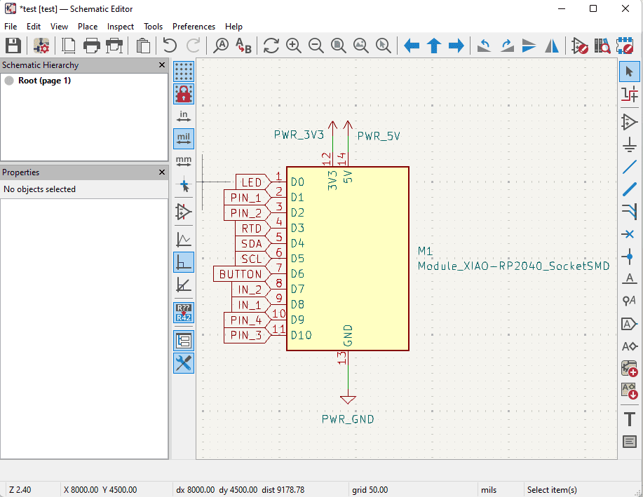
XIAO Seeed RP2040 is a tiny, powerful microcontroller board based on the Raspberry Pi RP2040 chip. It features a dual-core ARM Cortex-M0+ processor running at 133 MHz, 264 KB SRAM, and 2 MB flash. The board has 11 GPIO pins, USB Type-C, and supports I2C, SPI, UART, PWM, and ADC. Thanks to its small size and low power consumption, it’s great for wearables, DIY electronics, and IoT projects.
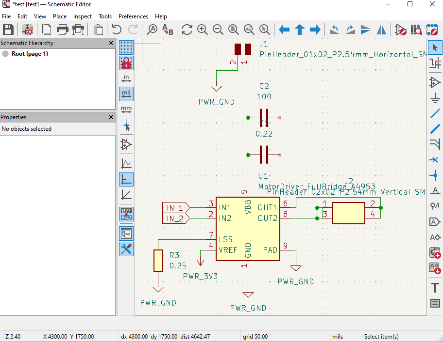
The motor driver was a bit tricky. I found resources here for the module I am using.
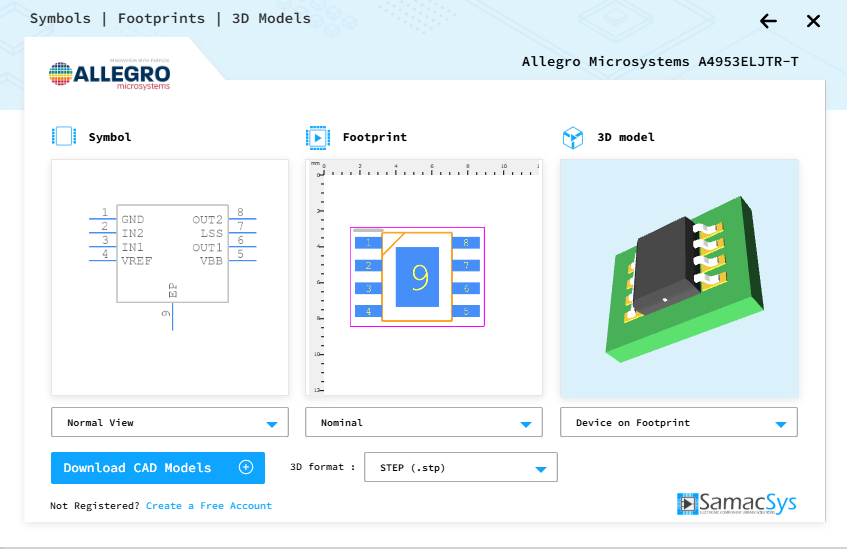
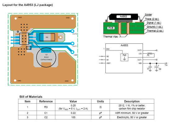
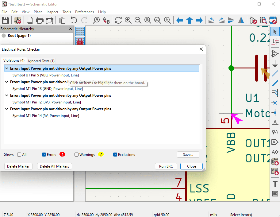
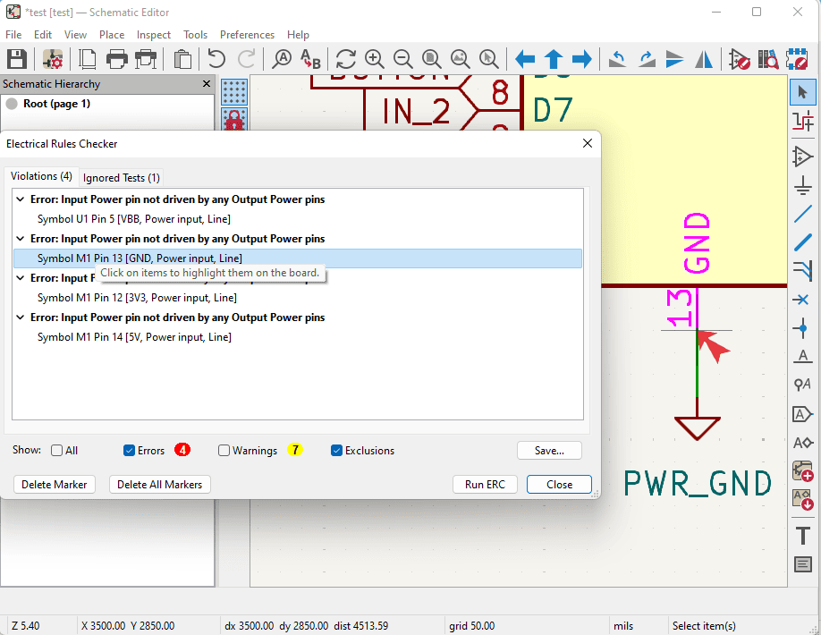
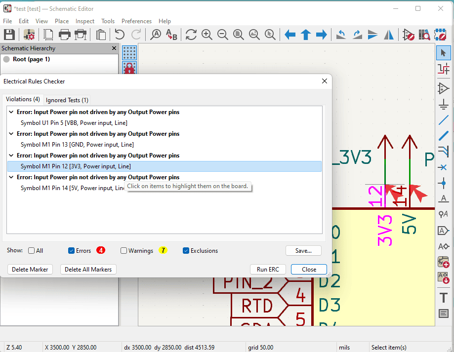
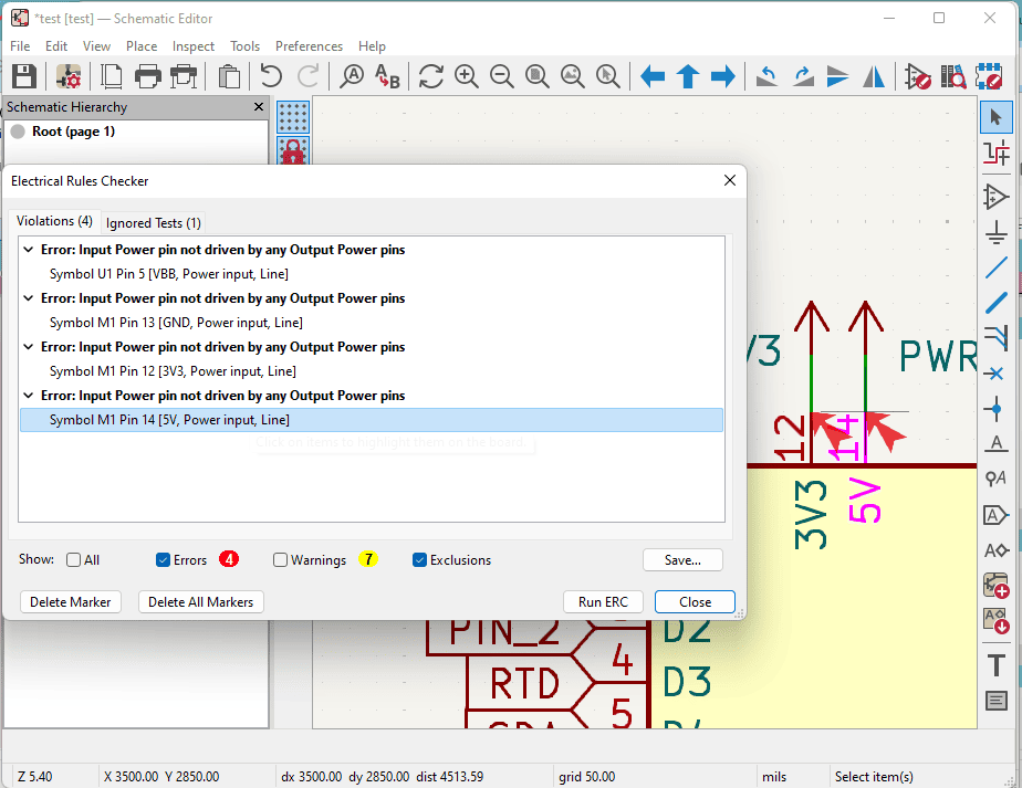
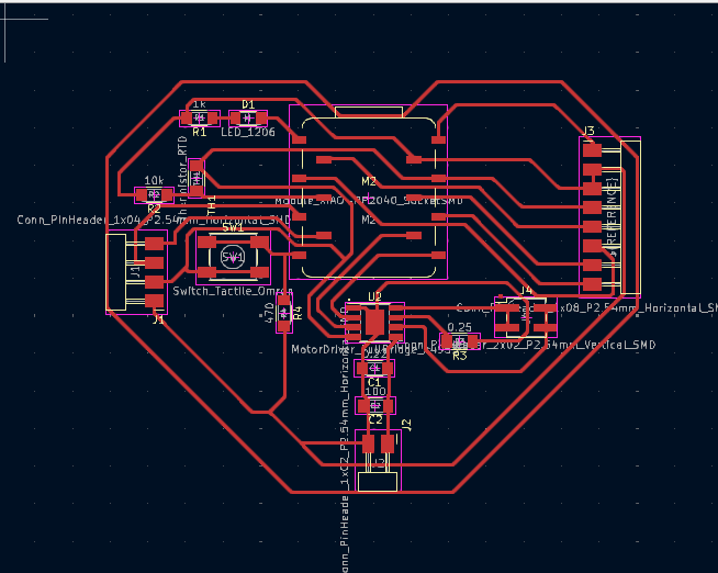
These diagrams and data helped me with figuring out how the schematics should be.
In the group assignment, we tested using the multimeter, the oscilloscope, and Picoscope.
Okay, so here's what actually sunk in after all that time poking at circuits:
Bottom line? Electronics are alive, they have moods, and nothing ever works perfectly the first time. And that's actually what makes it fun.
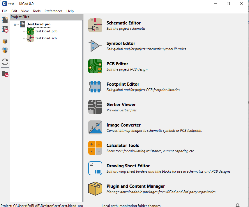
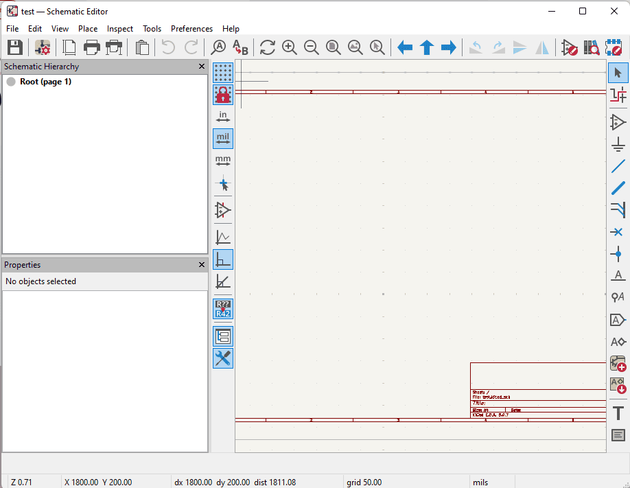
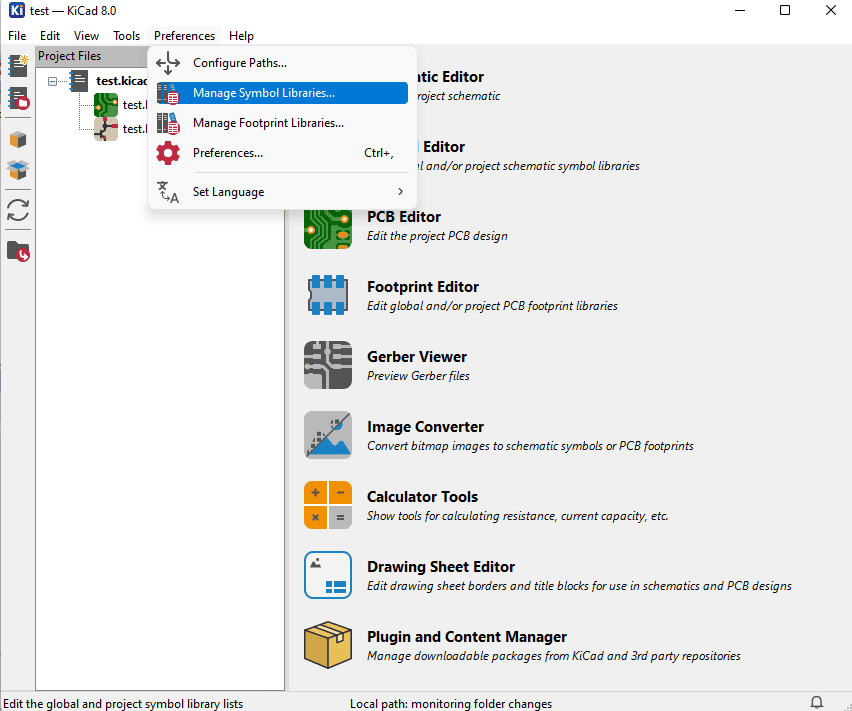
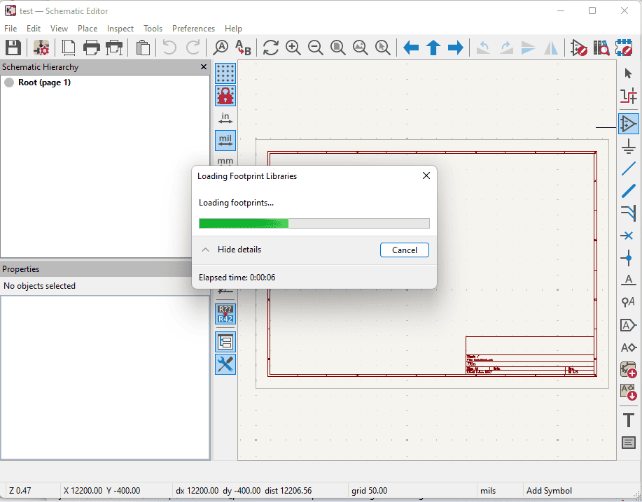
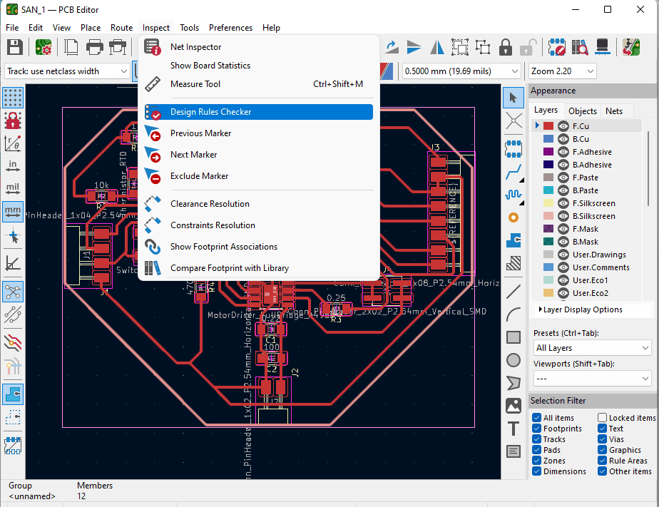
Group Assignment PageTheory is over, time to craft. After understanding and reading about the lectronics that I will use in my design, now it is time to purt them on my crafting table.
| Component | Footprint / Type | Quantity | Value |
|---|---|---|---|
| Pin Header 1x04 Horizontal | PinHeader_1x04_P2.54mm_Horizontal | 1 | — |
| Pin Header 1x02 Horizontal | PinHeader_1x02_P2.54mm_Horizontal | 1 | — |
| Pin Header 2x02 Vertical | PinHeader_2x02_P2.54mm_Vertical | 1 | — |
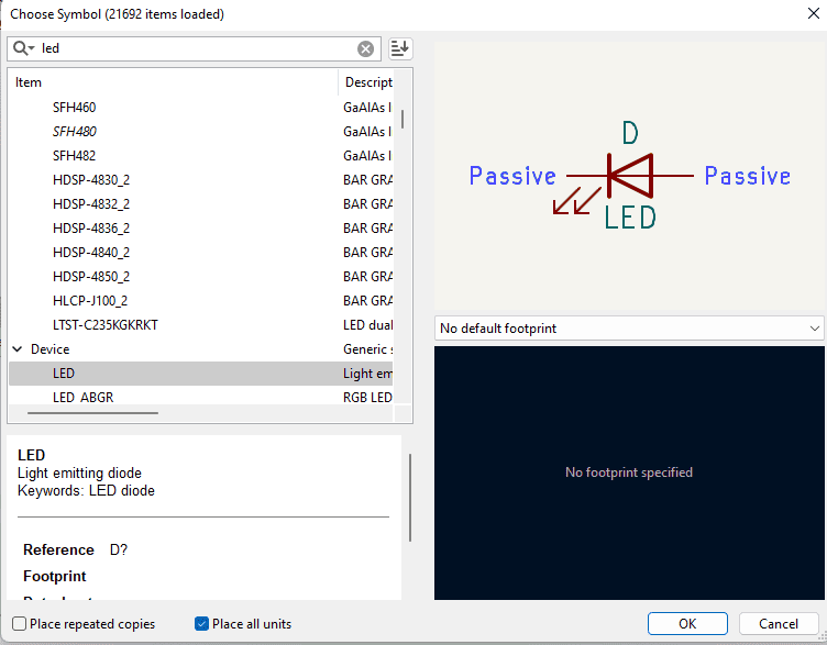
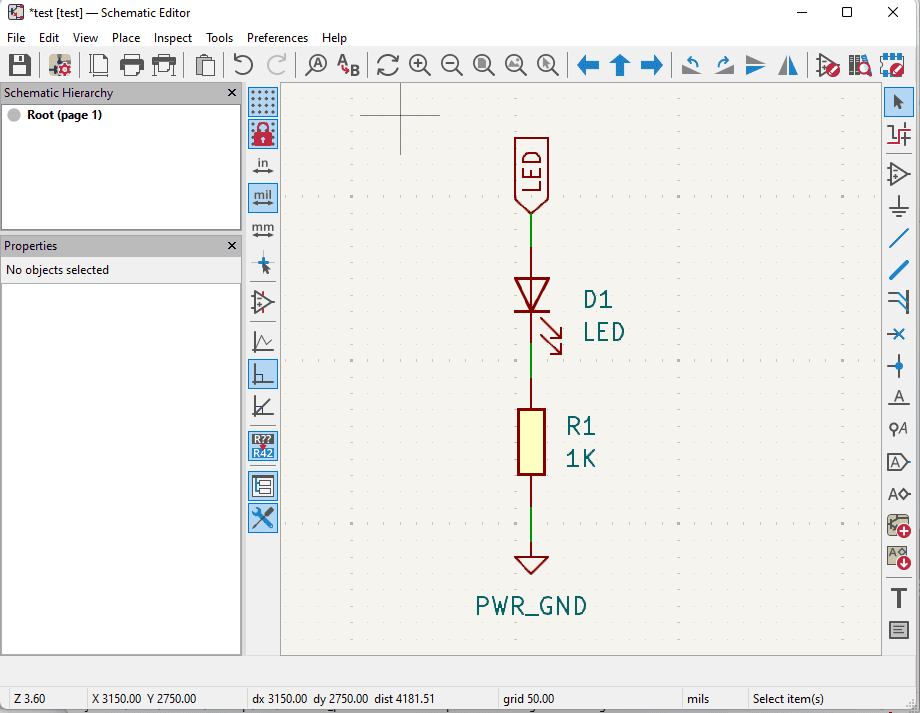
| LED | 1206 | 1 | — |
| Resistor | 1206 | 1 | 470 Ω |
| Seeed Studio XIAO Socket | Module_XIAO-RP2040_Socket | 1 | — |
| Motor Driver | SOIC-8 A4953 | 1 | — |
| Pin Header 1x08 Horizontal | PinHeader_1x08_P2.54mm_Horizontal | 1 | — |
| Resistor | 1206 | 1 | 0.25 Ω |
| Resistor | 1206 | 1 | 1 kΩ |
| Capacitor | 1206 | 1 | 100 µF |
| Capacitor | 1206 | 1 | 0.22 µF |
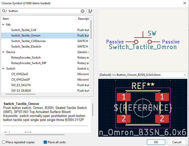
| Tactile Button | Omron B3SN 6x6 mm | 1 | — |
| Resistor | 1206 | 1 | 10 kΩ |
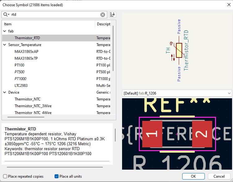
| Thermistor | RTD | 1 | — |

 \
\