

Embedded Programming
Overview
This week I worked on programming a microcontroller. I used two different coding environments: TinkerCAD Circuits and Arduino IDE.
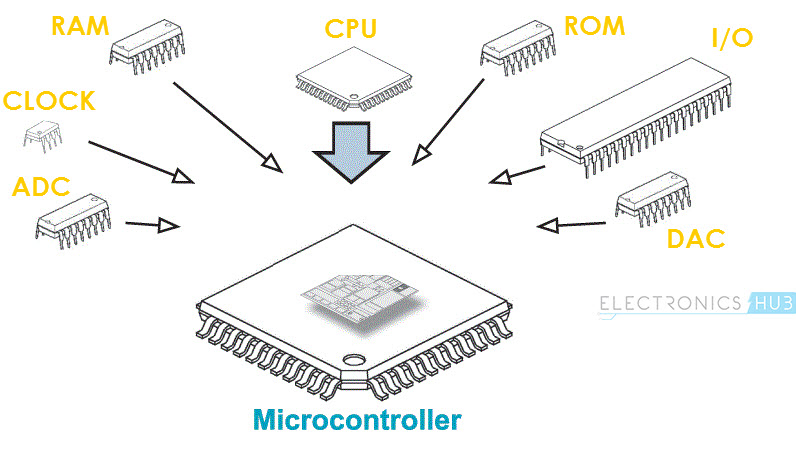
What is a microcontroller?
"A microcontroller is a compact integrated circuit designed to govern a specific operation in an embedded system. A typical microcontroller includes a processor, memory and input/output (I/O) peripherals on a single chip."
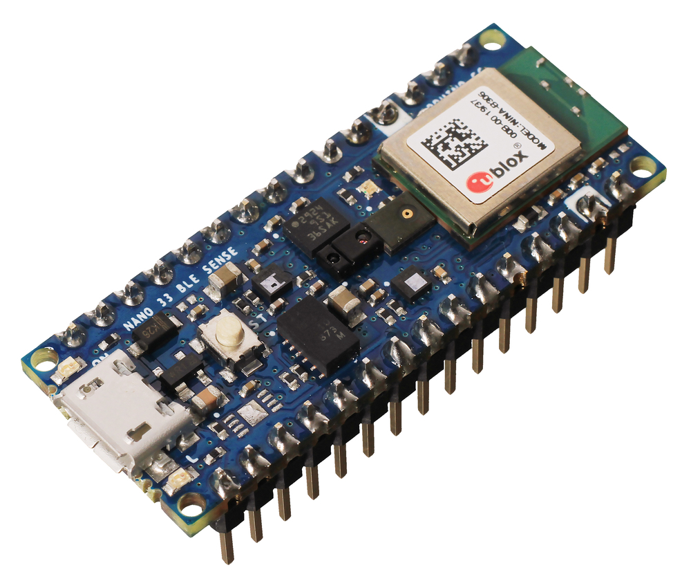
The type I am using is Arduino Nano 33 BLE Sense.
Arduino Nano 33 BLE Sense
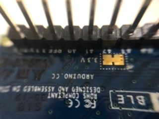
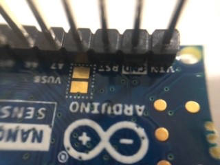
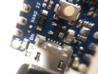
The Arduino Nano 33 BLE looks as shown in the picture below.
But what is Arduino? It is one of the most famous companies dealing with programming and microcontrollers.
Arduino
As the official Arduino website says:
"Arduino is an open-source electronics platform based on easy-to-use hardware and software. It's intended for anyone making interactive projects."
Datasheet and Research
The Arduino Nano 33 BLE Sense is a hardware device, a microcontroller used to make many different projects. It’s listed on the official Arduino website under “Enhanced Features” and is the smallest available form from Arduino’s 3.3V AI board lineup.
It has many features, starting with its sensors:

As seen in the graph, it has five different built-in sensors.
One impressive feature is that this microcontroller can run Edge Computing applications, including Artificial Intelligence.
Besides the useful sensors, the Arduino Nano 33 BLE Sense also comes with Bluetooth for wireless connectivity. BLE stands for Bluetooth Low Energy, which uses low energy and has a low data rate. Watch this video on using BLE.
More features, as stated in the Arduino Nano 33 BLE Datasheet, include flexible power management, an advanced security subsystem, 1 MB flash, 256 kB RAM, and others.
Pinouts on the Microcontroller
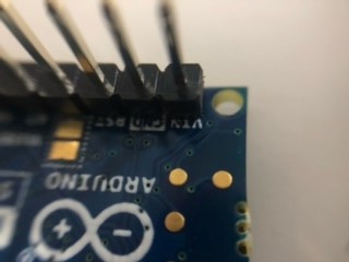
- The Vin, or voltage input, is the primary voltage source for the board:
- Digital pins — 14 pins that work in binary states (On/Off):
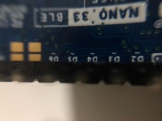
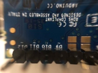
- Analog pins — 8 pins that read values from analog sensors:
Note
Digital devices can work when connected to analog pins, but the opposite does not work.
- GND (Ground), where the voltage is zero:
- To see the rest of the pinouts and their positions, refer to the following diagram:
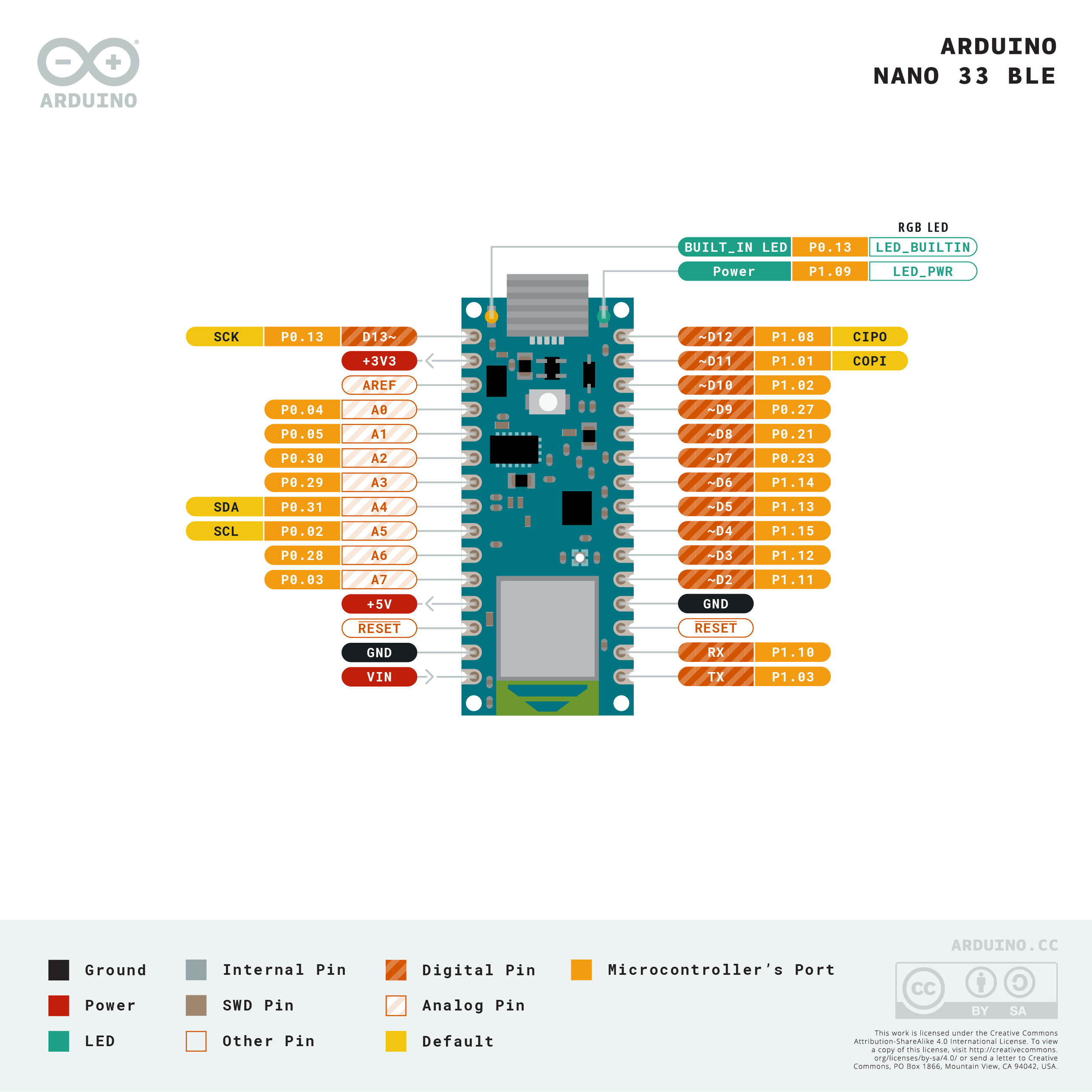
- The power LED turns green when power is on:
Group Assignment
Find details about differenttoolchains and development workfolow in out group assignment page:
Group Assignment Pageprogramming
There are different software tools to program the device offline and online like Arduino IDE, Arduino CLI, and TinkerCAD. I used Arduino IDE and TinkerCAD to test the difference between coding typically and coding by code blocks.
Using ARDUINO IDE
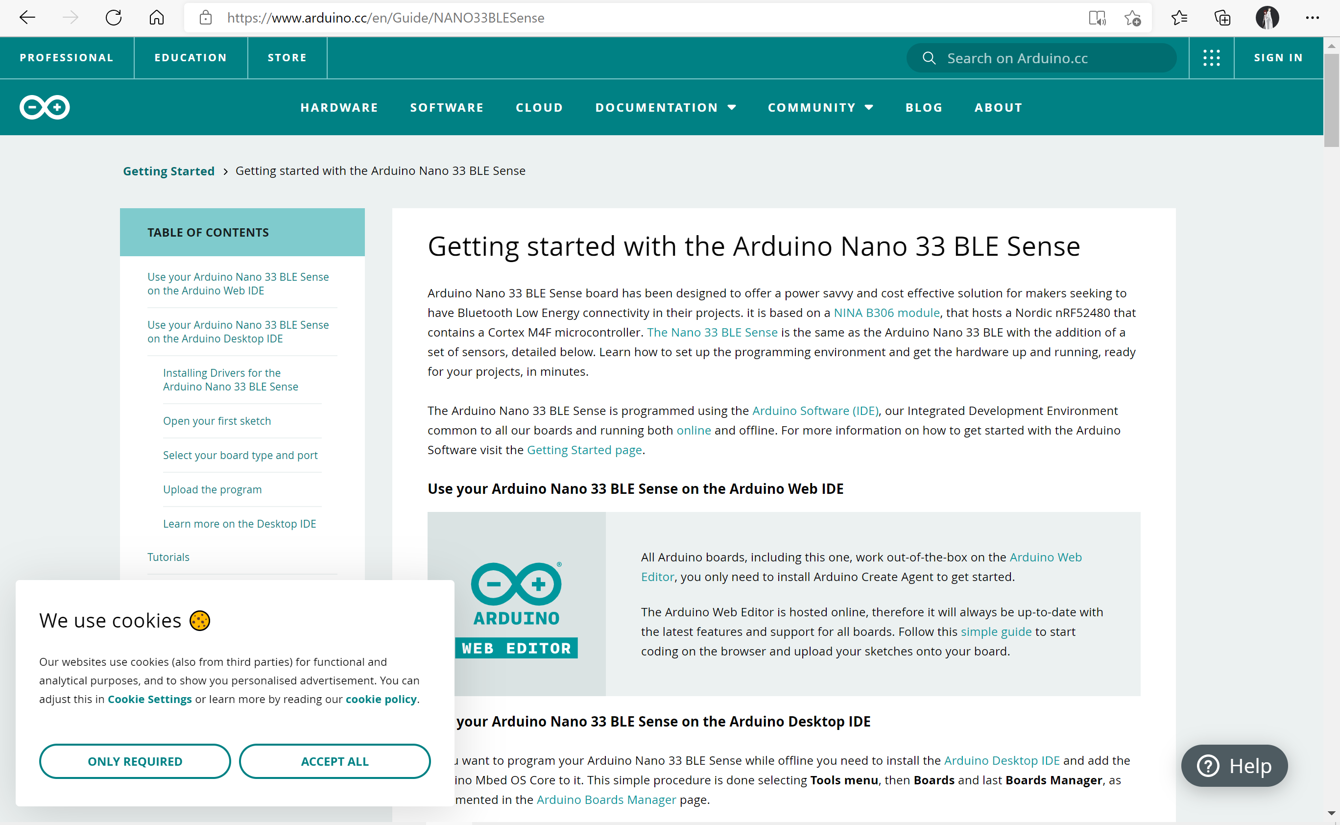
- Start with downloading the app for Arduino from their official website here.
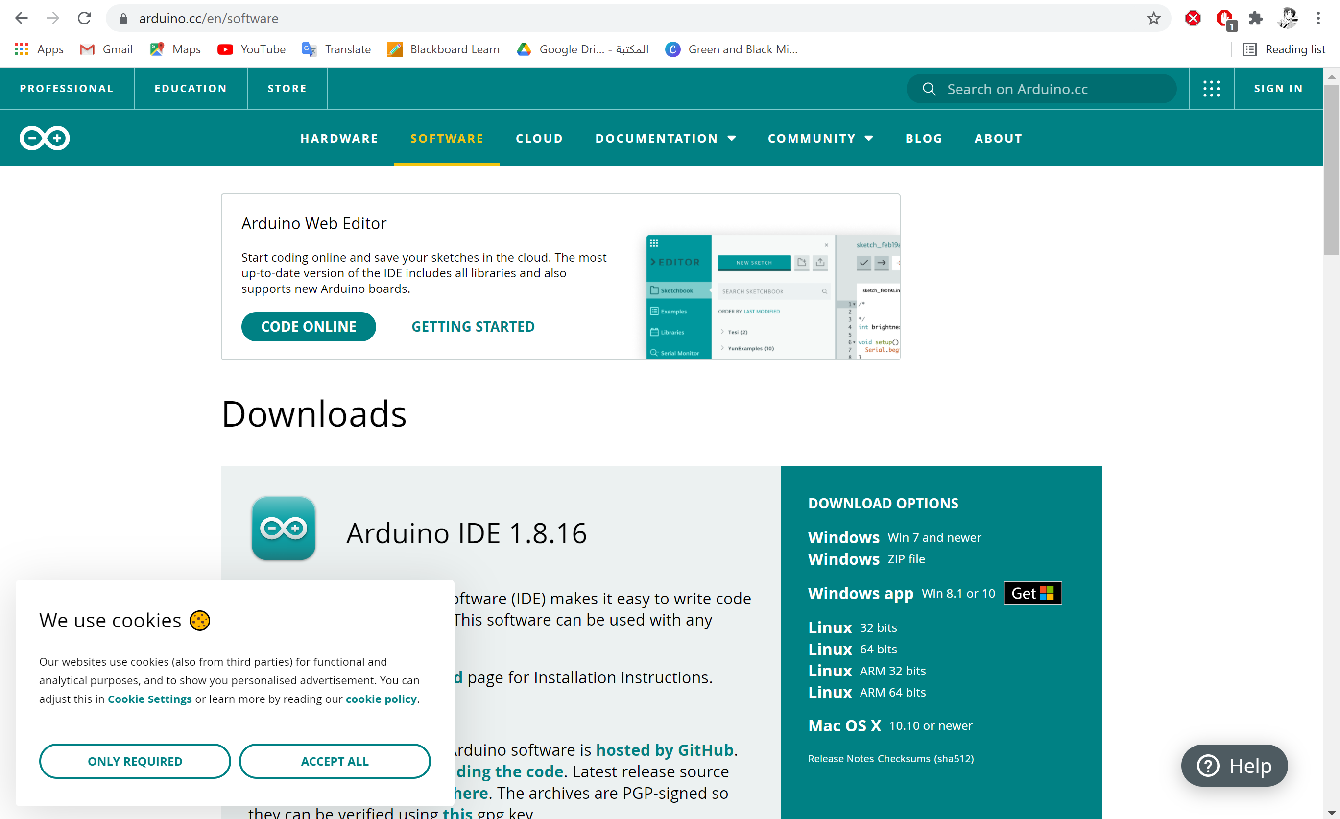
- The page looks like this after downloading.
- Followed this tutorial to get to know how to use Arduino and connect the device to Arduino IDE.
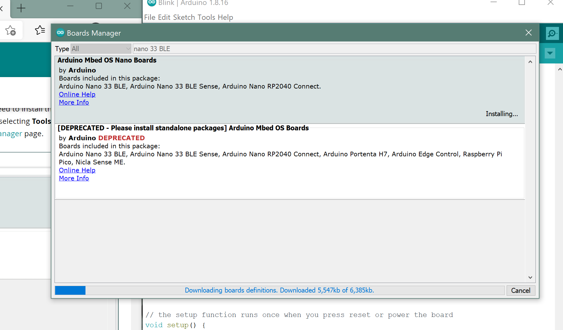
- It required downloading the board to the Arduino IDE.
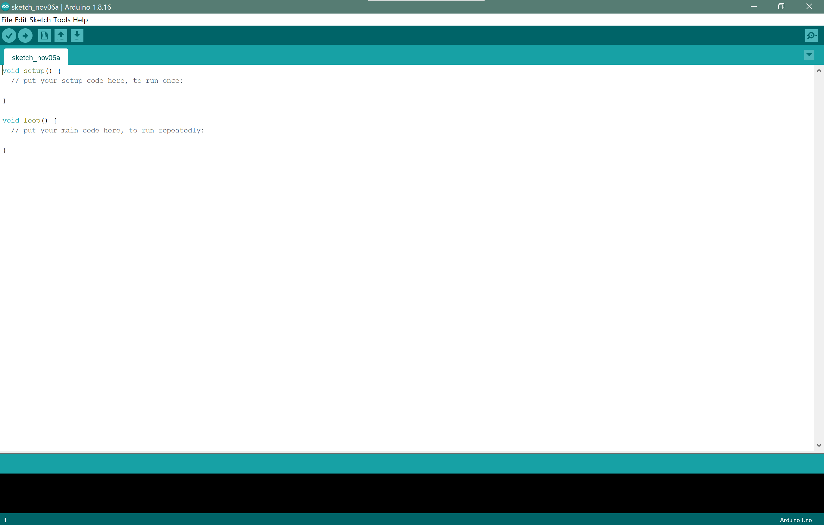
- Started looking for examples that came along with Arduino IDE.
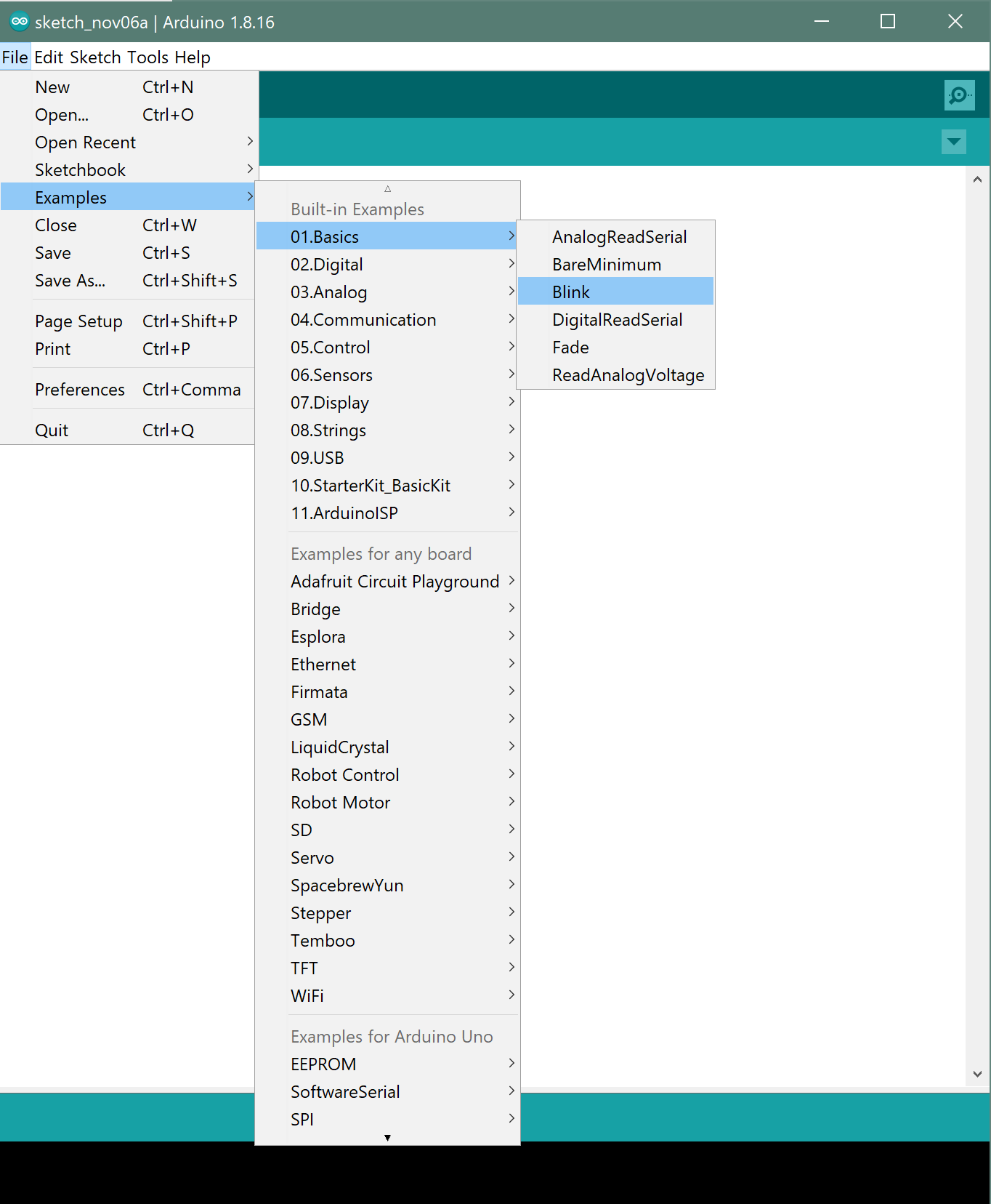
- The example I tried is the Blink Example, which makes the programmable LED light (Orange) turn on for one second and off for one second repeatedly. I found the comments in the example very helpful to understand the code.
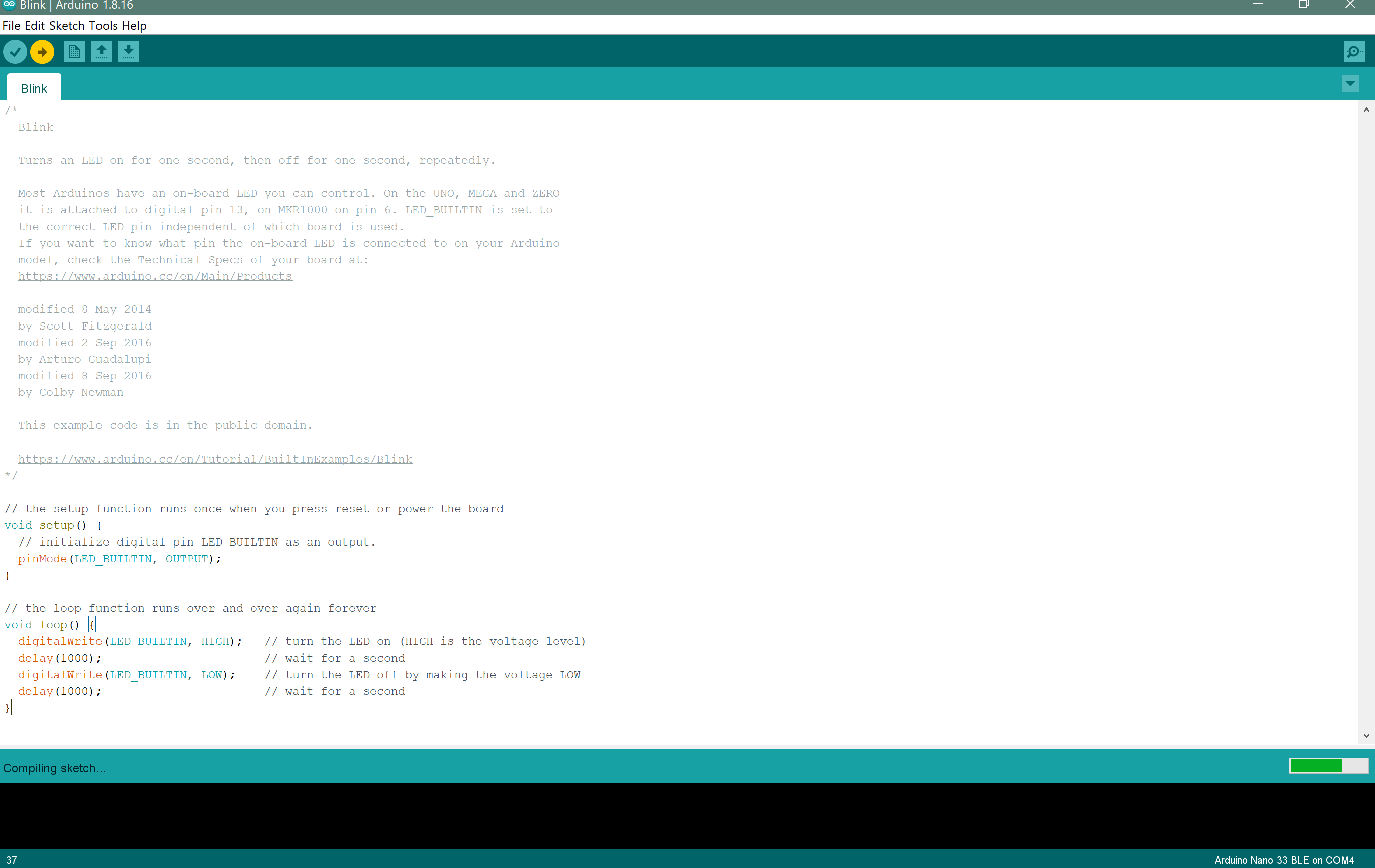
- I ran the Blink example on my board, which worked just by choosing its port from Tools> Port and then choosing the correct port.
Note:
It seems that every time I upload the program, I need to redo the previous step again, which is choosing the correct port.
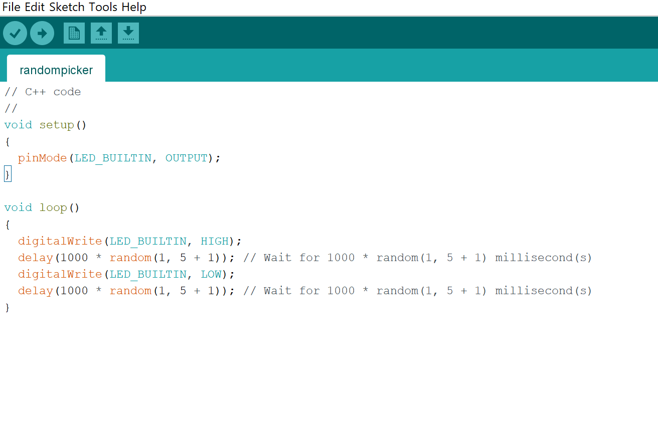
- Then I tried making the light turn on for random times, using the function random, for more info.
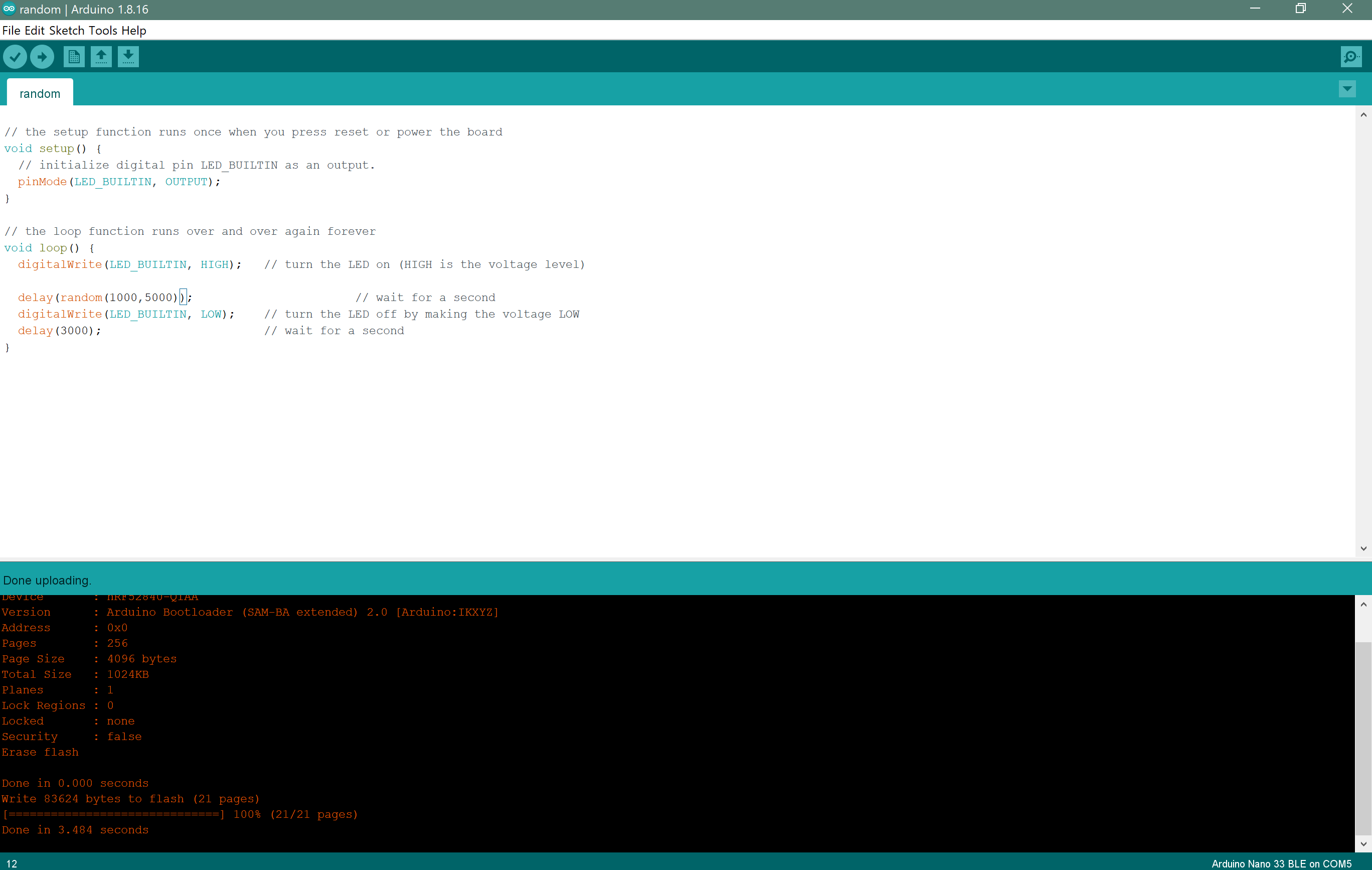
// the setup function runs once when you press reset or power the board
void setup() {
  // initialize digital pin LED_BUILTIN as an output.
  pinMode(LED_BUILTIN, OUTPUT);
}

// the loop function runs over and over again forever
void loop() {
  digitalWrite(LED_BUILTIN, HIGH);   // turn the LED on (HIGH is the voltage level)
  delay(random(1000,5000));             // wait for random time between 1 - 4 seconds
  digitalWrite(LED_BUILTIN, LOW);    // turn the LED off by making the voltage LOW
  delay(3000);                       // wait for 3 seconds
}
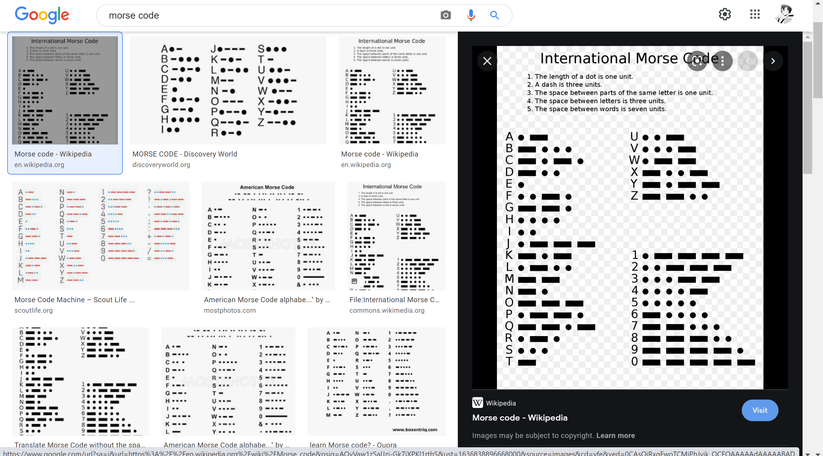
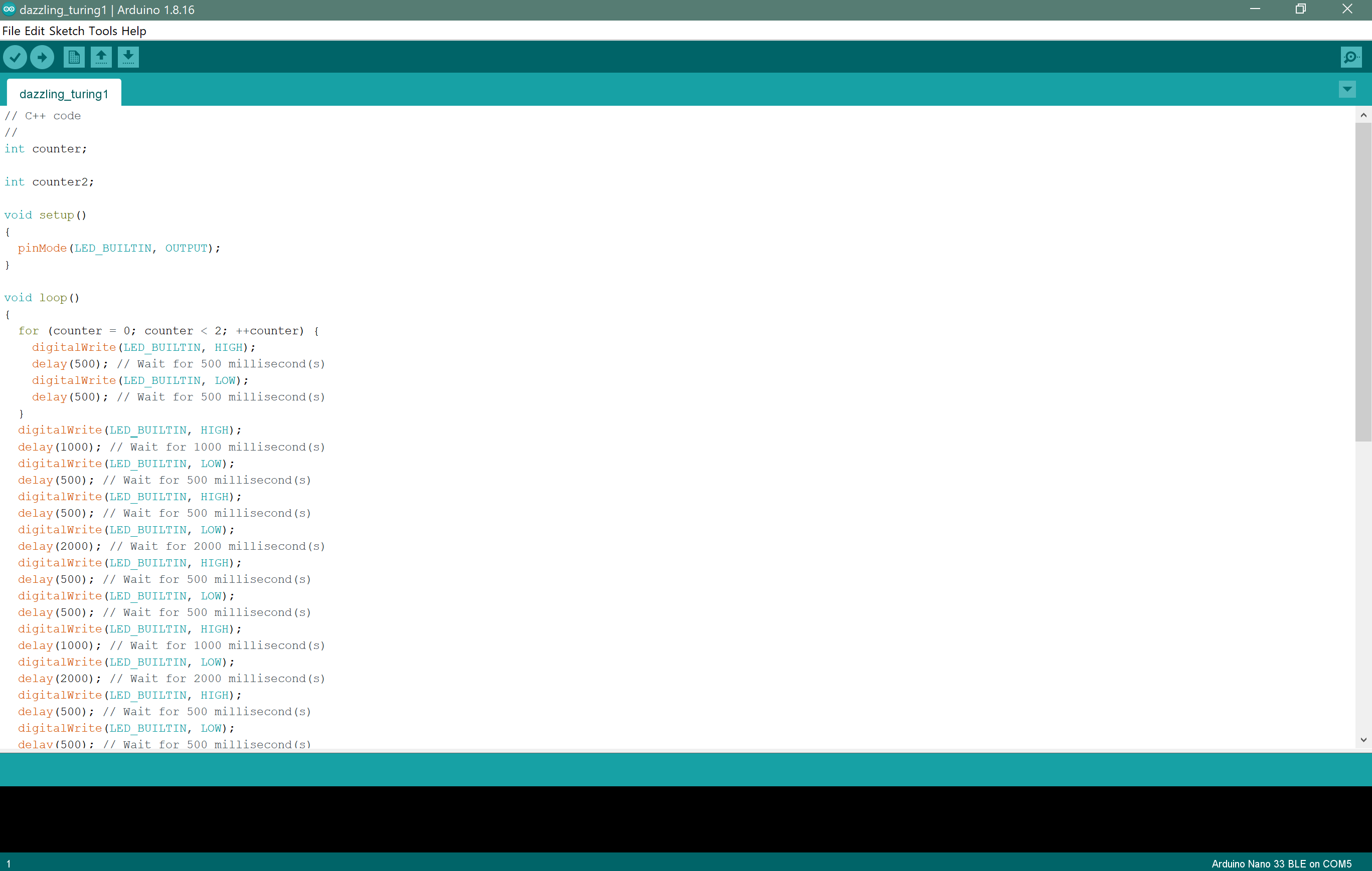
- Then I used this experience to make the light turn on and off as a Morse code spelling "fablab".
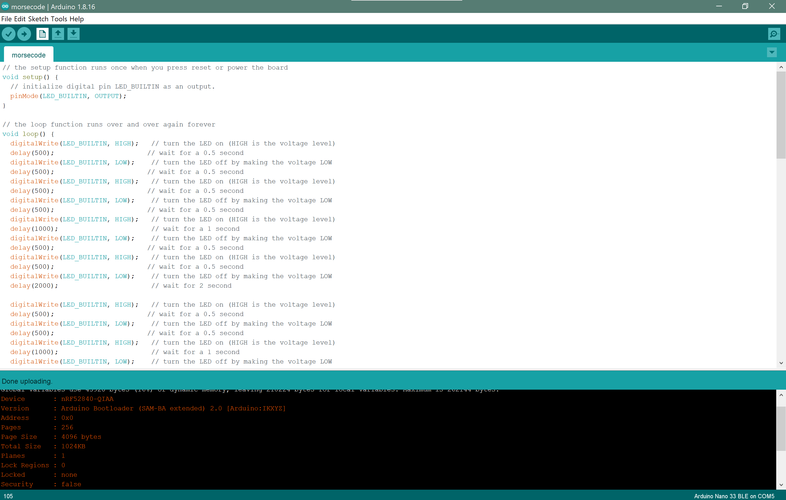
// the setup function runs once when you press reset or power the board
void setup() {
  // initialize digital pin LED_BUILTIN as an output.
  pinMode(LED_BUILTIN, OUTPUT);
}

// the loop function runs over and over again forever
void loop() {
  digitalWrite(LED_BUILTIN, HIGH);   // turn the LED on (HIGH is the voltage level)
  delay(500);                       // wait for a 0.5 second
  digitalWrite(LED_BUILTIN, LOW);    // turn the LED off by making the voltage LOW
  delay(500);                       // wait for a 0.5 second
  digitalWrite(LED_BUILTIN, HIGH);   // turn the LED on (HIGH is the voltage level)
  delay(500);                       // wait for a 0.5 second
  digitalWrite(LED_BUILTIN, LOW);    // turn the LED off by making the voltage LOW
  delay(500);                       // wait for a 0.5 second
  digitalWrite(LED_BUILTIN, HIGH);   // turn the LED on (HIGH is the voltage level)
  delay(1000);                       // wait for a 1 second
  digitalWrite(LED_BUILTIN, LOW);    // turn the LED off by making the voltage LOW
  delay(500);                       // wait for a 0.5 second
  digitalWrite(LED_BUILTIN, HIGH);   // turn the LED on (HIGH is the voltage level)
  delay(500);                       // wait for a 0.5 second
  digitalWrite(LED_BUILTIN, LOW);    // turn the LED off by making the voltage LOW
  delay(2000);                       // wait for 2 second
}
See this video of the code running FABLAB in Morse Code:
or from this link
Downloads
Using TinkerCAD Code Blocks
Code Blocks is an easier way for coding, which uses blocks that connect together to make a code, and a live simulation could be seen.
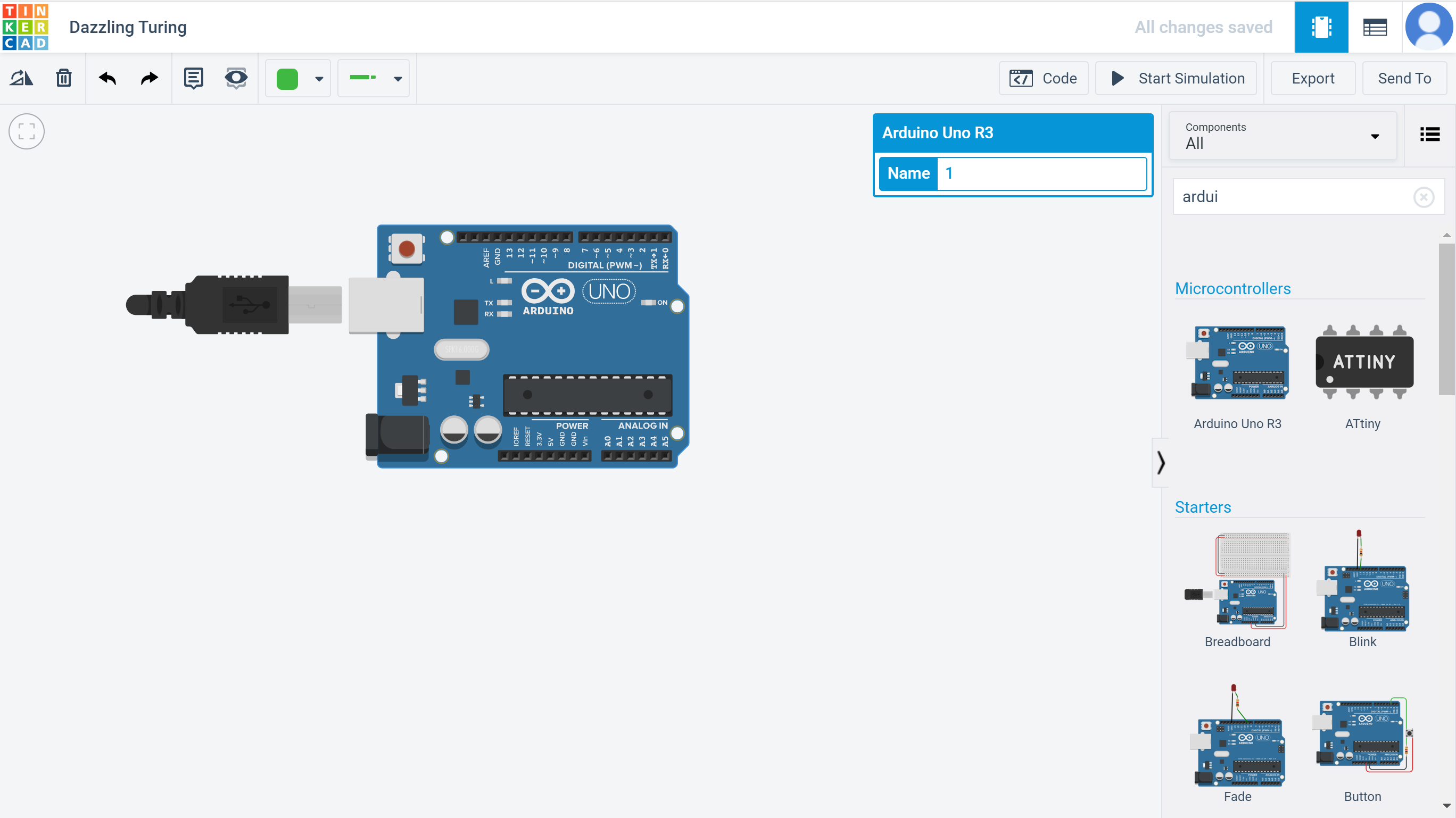
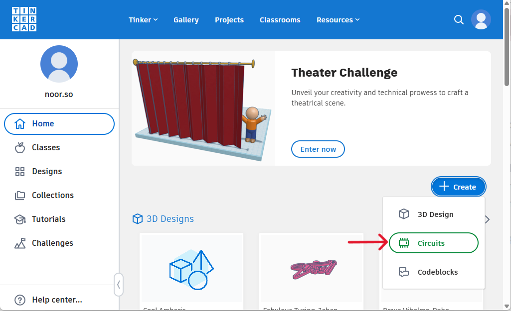
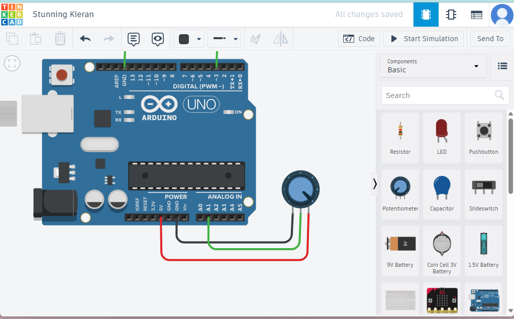
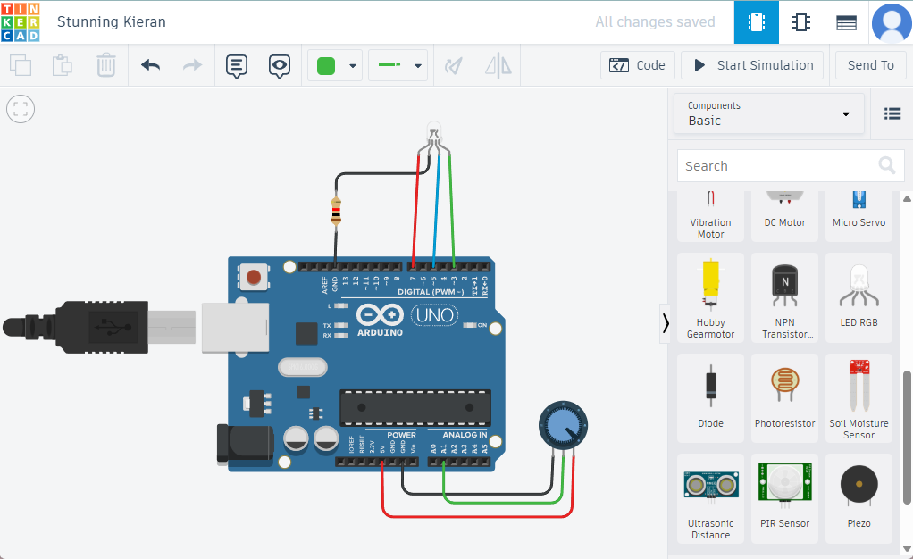
- First I opened TinkerCAD Circuits
- Then click on Create New Circuit.
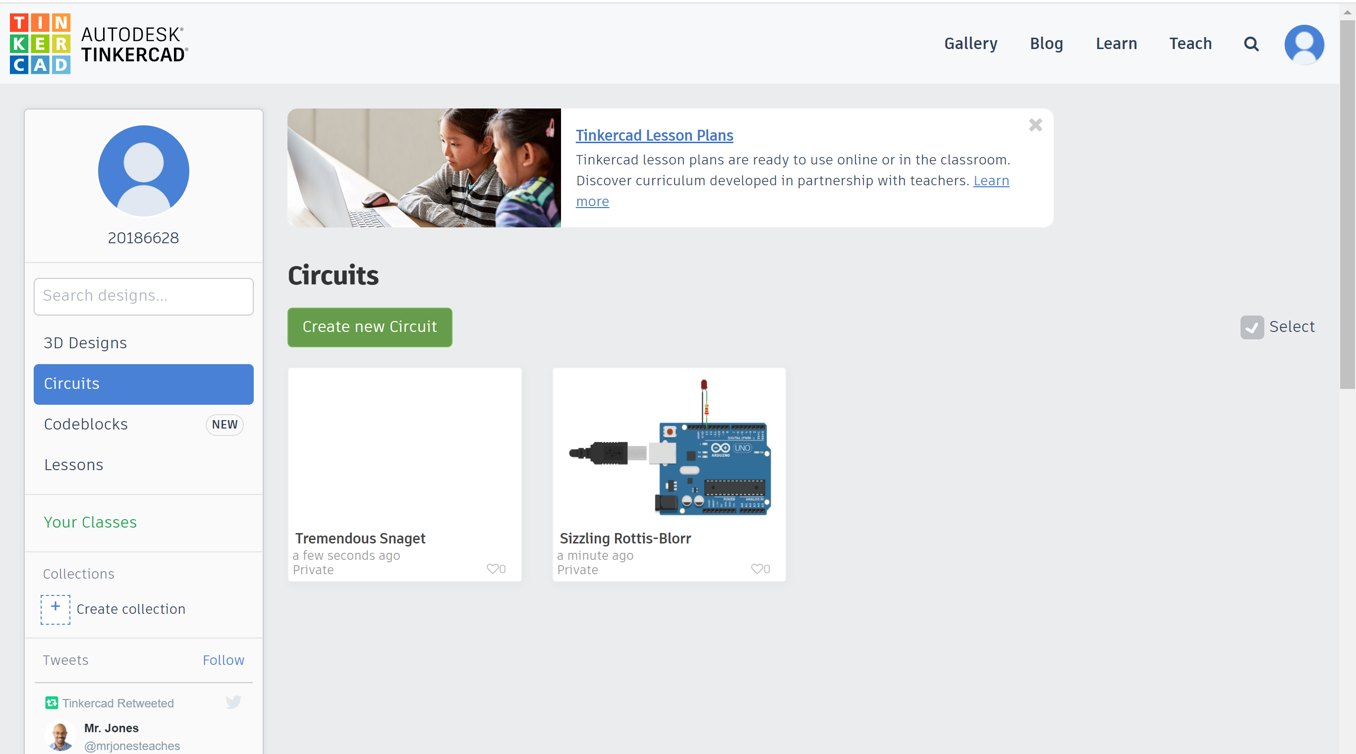
- Then choose the device you are working with from Components, I chose the Arduino Uno R3 because Arduino Nano 33 BLE was not available, but it was fine.
- You can find examples just like Arduino IDE, I wanted to try doing the same work I did in Arduino IDE here, I started with the blink example.
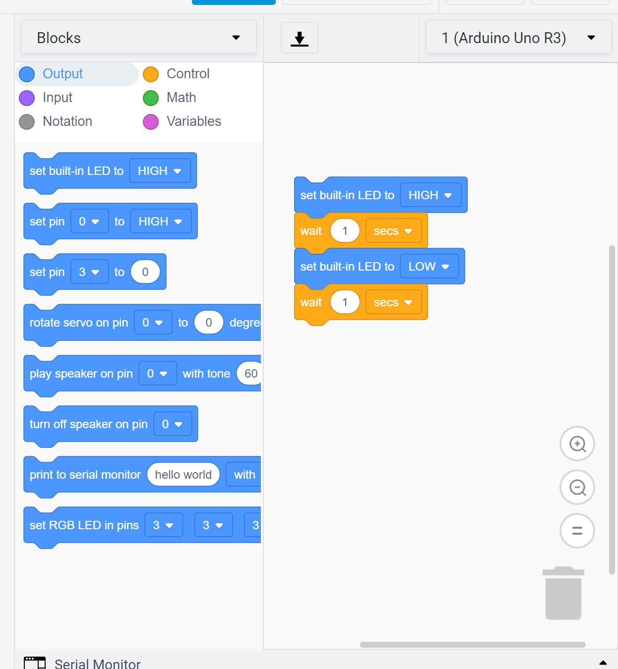
- Then I wanted to make it run for random time between 1 to 5 seconds. In the blocks go to Math and choose Pick Random.
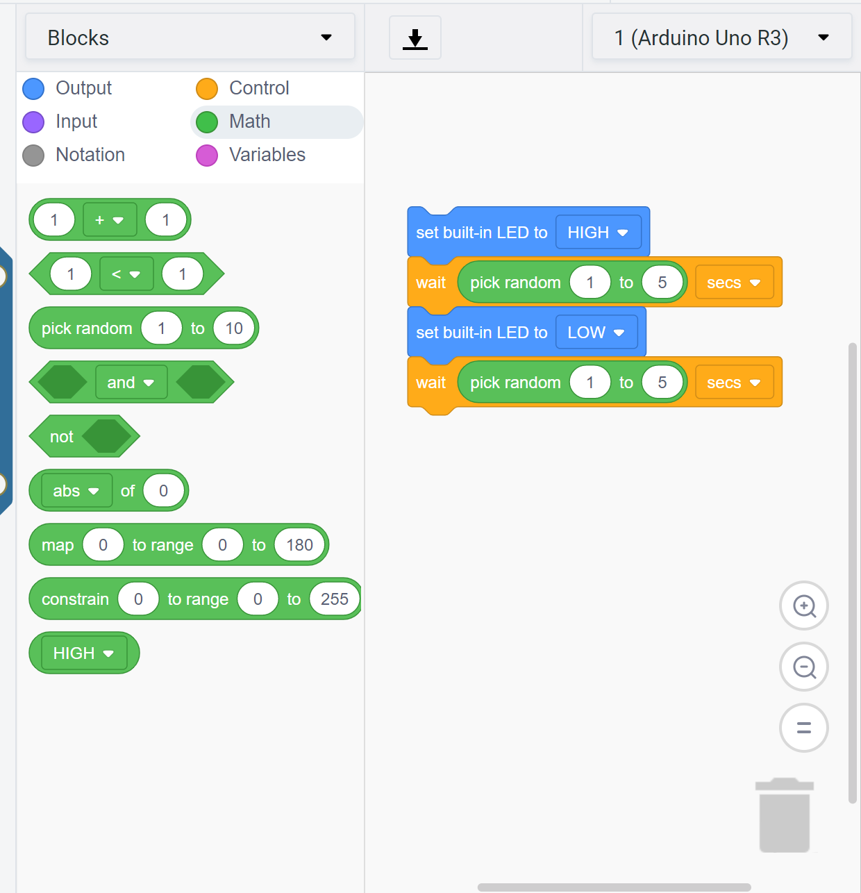
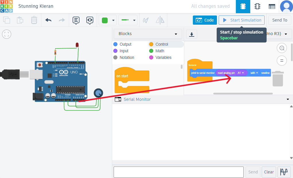
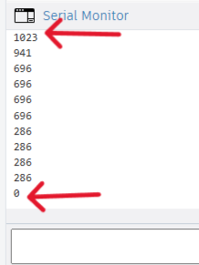
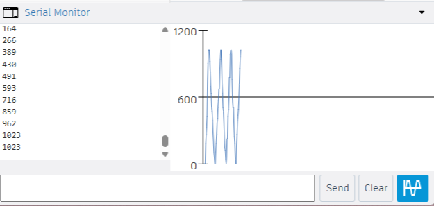
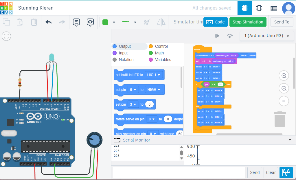
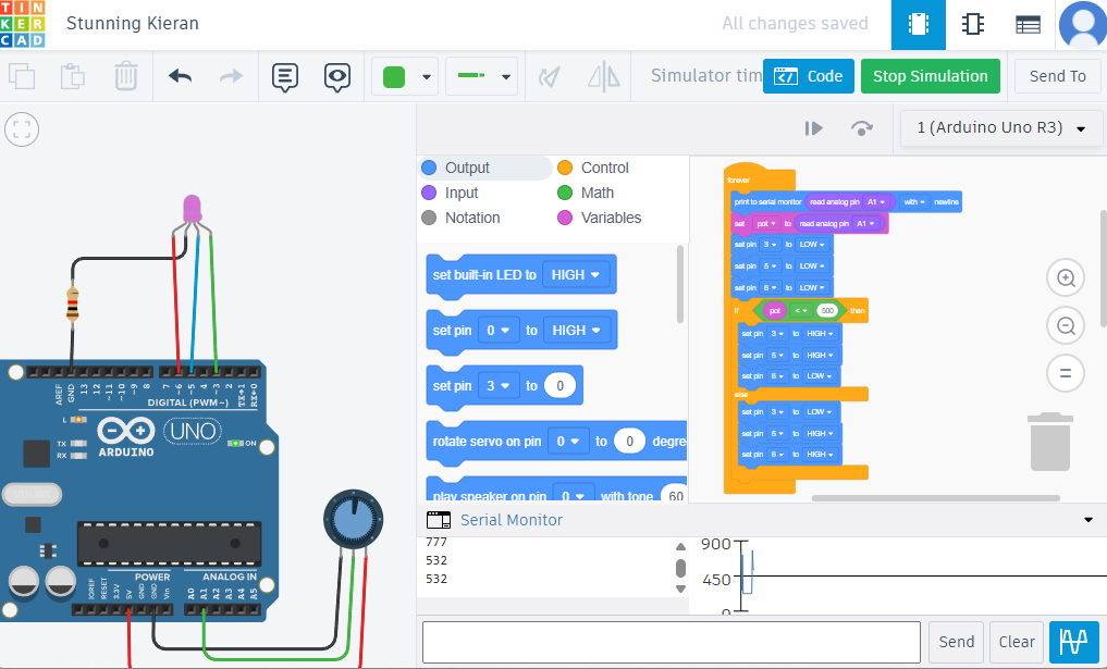
- To view if the code works, press Simulate, as seen the light turns on and off.

- Then I downloaded the code to try it on the board from the arrow.
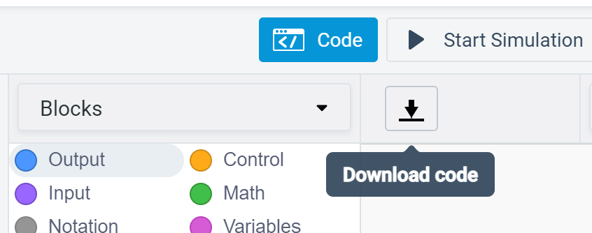
- It then downloaded into a C++ code, which was pretty cool with the comments and explanations.
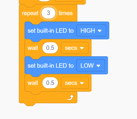
- Then I wanted to redo the Morse code I did with Arduino IDE.
- One good thing that helped me in Code Blocks is the use of the repeat block. I used it for situations where I had more than one dot or dash following each other.
- Similarly I downloaded the code and tried it on the microcontroller I have, and it worked perfectly just like the code I did with Arduino IDE.
Downloads
Personal Evaluation:
- I found Arduino IDE easy to learn from the provided examples and the references on their official website.
- TinkerCAD Circuits is more of a fun way to code. It provides some useful Math tools and statements that can be used. A great thing is that after downloading the code, you can see the comments explaining what each code statement does. Moreover, the live simulation gives you a pretty good view of what the code does.
Simulation
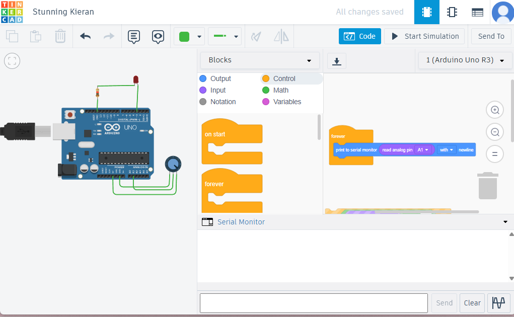
TinkerCAD Circuits
I used the amazing TinkerCAD circuits to simulate and code an input with an output.
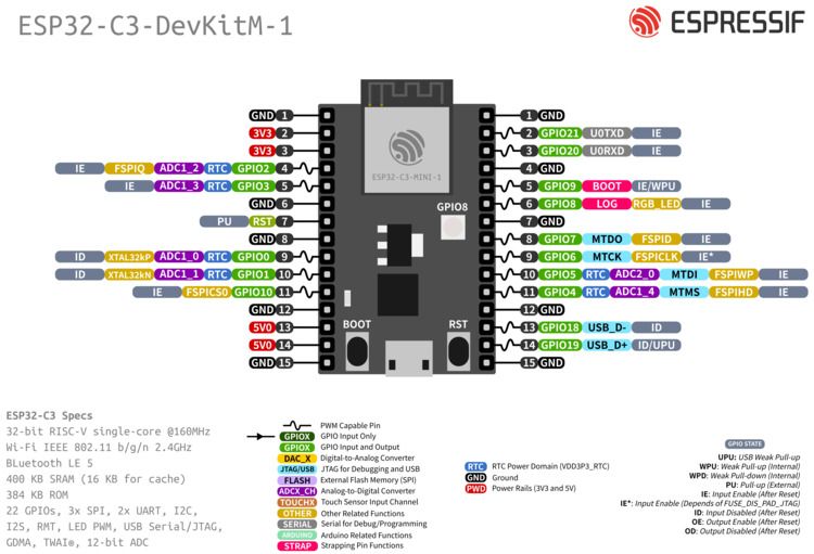
ESP32 C3 Mini1
Let's Learn about it
ESP32-C3-MINI-1 is a compact Wi-Fi and Bluetooth Low Energy (BLE) combo module from Espressif Systems. Built around the ESP32-C3FN4 chip, it integrates a 4 MB flash memory and offers 15 GPIOs. The module supports 2.4 GHz Wi-Fi (802.11 b/g/n) and Bluetooth 5.0, making it ideal for IoT applications requiring efficient connectivity in a small form factor.
Datasheet & Research
For detailed specifications and technical information, refer to the official datasheet:
- Chip: Based on ESP32-C3 with a RISC-V core
- Connectivity: Supports Wi-Fi (802.11 b/g/n) and Bluetooth 5.0 (BLE)
- GPIO Pins: 15 GPIO pins for interfacing with external components
- Built-in Peripherals: ADC, SPI, I2C, UART, and more
- Memory: 4 MB of flash memory for storage
- Security: Secure boot and flash encryption
- Power Efficiency: Low-power operation with deep sleep modes
- Development Compatibility: Compatible with Arduino IDE and ESP-IDF
- Applications: Ideal for IoT, smart devices, wearables, and sensor networks
ESP 32 C1 Mini 1 PINOUT
- GPIO0, GPIO2, GPIO4, GPIO5, GPIO12, GPIO13, GPIO14, GPIO15, GPIO16, GPIO17, GPIO18, GPIO19, GPIO20: General-purpose I/O pins, can be used for various functions such as UART, SPI, I2C, PWM, and more.
- GPIO1 (TXD) & GPIO3 (RXD): UART0 communication (Transmit and Receive data pins).
- GPIO6, GPIO7, GPIO8, GPIO9, GPIO10, GPIO11: Flash chip pins, should not be used as general-purpose I/O.
- EN (Enable Pin): Pin to enable or reset the ESP32-C3 chip.
- 3V3 (Power Pin): Provides 3.3V output.
- GND (Ground Pin): Ground connection for the board.
- 5V (Power Pin): Provides 5V input voltage to the board.
Programming & Simulation
After reading about ESP32 C3 Mini 1, and figuring out the pinouts, Now it is time for Wokwi.
For my final project, I am building a board game, and part of it is to figure out obstacles. An Ultrasonic sensor will be usefull with that.
Functionality:
This code is for an ultrasonic distance measuring project. It uses an ultrasonic sensor to measure the distance to an object and displays the value on an OLED screen. The setup also includes serial output to monitor the distance readings via the Serial Monitor.
Main Components:
- Ultrasonic Sensor: Used to measure the distance. The sensor works by sending out a pulse and measuring the time it takes for the pulse to bounce back from an object. The time is then converted into distance.
- OLED Display: A 128x64 pixel display used to show the measured distance in centimeters. It uses the I2C protocol for communication.
- Arduino Code: This code controls the sensor, processes the input, and displays the results on the OLED. It also prints the distance to the Serial Monitor.
Code Breakdown:
- Libraries Used:
- Wire.h: I2C communication library.
- Adafruit_GFX.h: Graphics library for OLED display.
- Adafruit_SSD1306.h: SSD1306 OLED display control library.
- Pin Setup: The ultrasonic sensor's TRIG and ECHO pins are connected to GPIO18 and GPIO19, respectively. The I2C communication for the OLED is handled by GPIO4 (SDA) and GPIO5 (SCL).
- Distance Measurement: The sensor sends out a pulse and measures the time it takes for the pulse to return. The duration is then converted into distance using the formula: distance_cm = duration * 0.0343 / 2.
- OLED Display Update: The OLED display is cleared and updated every 500 milliseconds to show the new distance reading. The result is shown with 2-digit precision in centimeters.
- Serial Output: The distance is also printed to the Serial Monitor for debugging and monitoring purposes.
How it Works:
- 1. The ultrasonic sensor sends out a pulse when the TRIG pin is set HIGH for 10 microseconds. The echo pin measures the time it takes for the pulse to return.
- 2. The distance is calculated using the pulse duration and displayed on the OLED screen. The same distance is also sent to the Serial Monitor every 500 milliseconds.
- 3. The OLED updates every half second, displaying the most recent measurement of the distance in centimeters.