Output devices
9.1 Group assignment | Measure the power consumption of an output device.
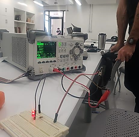
This week we measured an output device, in this case was an LED, using two measurement instruments: a RIGOL DP832A power supply and a Steren brand multimeter.
Below I show photographic evidence of our process. If you want to see our complete development, click on our laboratory page, here

9.2 Group assignment | Personal conclussions
As you can see in the images, we made both measurements on a protoboard with a LED and a resistor.
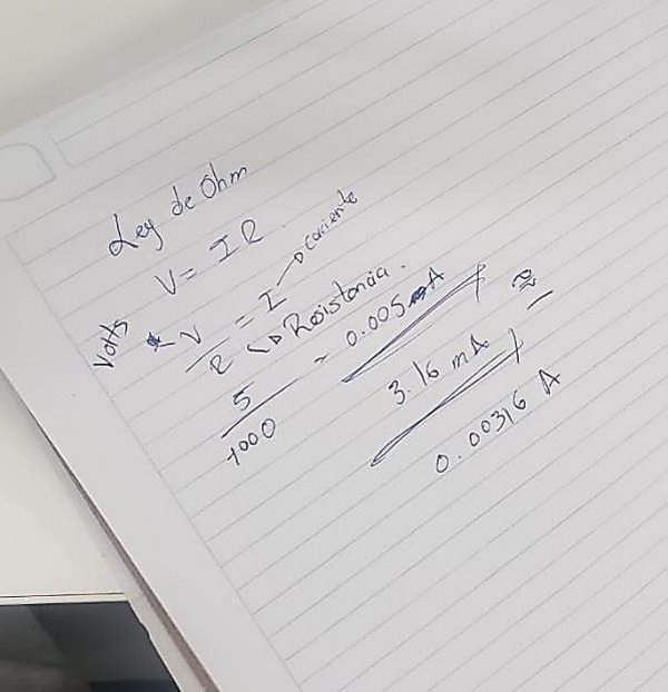
But first of all we checked, according to Ohm's law, the values that should be shown by both measuring instruments, and according to the theory: with the formula, the most accurate value was the one of the power supply, however both are on the acceptable range, so in the future, we could use either of the two.
Obviously, the power supply is more accurate since it has more control points.
It is very important to make these types of measurements as the project progress to prevent it from collapsing and potentially causing damage to both the circuits and components and the users.
It is our responsibility as designers to ensure that electronic circuits are calibrated correctly.
9.3 Individual assignment | add an output device to a microcontroller board you've designed, and program it to do something
Unfortunately I have not been able to finish the previous assignment, I am completely overwhelmed, I have been searching how to design my PCB card with Kicad and Fusion, which until now I only intend to connect a humidity sensor, but I don't know how to continue on my own.
I'm going to ask for help so I don't fall further behind.