Computer-aided design
2.1 Task: Evaluate & select 2D & 3D software
The assignment for this week was about trying with different software, preferably parametric in order to have more control with the 3D modeling.
I decided to use these 4 tools.
1rst: Rhino. Since I have more experience using it in 2 dimensions, I think is going to be easier to work it in 3 dimensions.
2nd: Solid Works. I've never used that software, but I'm going to try.
3rd. Vizcom. Using the sketch I did for the 1rst assignment as a generative reference to generate a render/s that shows the main idea for my final project.
4rd. Autocad. This is the software I feel most comfortable with, I use it mainly to draw architectural plans, but also to generate traces for laser cutting. Thinking about the processes of each component of my final project, I will most likely make the transparent dome in 2D, so I will generate a geometry very close to what I am imagining.
2.2 Task: Demonstrate and describe processes used in modelling with 2D and 3D software
This is the first time I explore Rhino in its 3D mode, I think is was not too difficult but definitely kind of overwhelming for me because i tried many times to make extrusions around a curve and I couldn't make it. So I decided to make all the model extruding curves. Hope to learn how to do it soon, I am going to ass a coworker named Raúl Moysen who is a crack using Rhino.
Below I will explain step by step what I did:
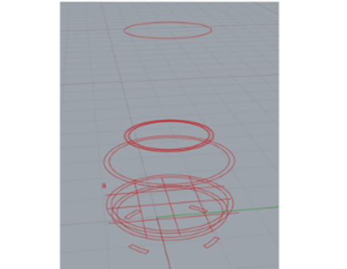
First
I generate circumferences to extrude from the bottom to the top of the model. I did all of them together because i wanted to make sure they didn't exceed 40 centimeters height since I want the plant incubator to be portable I wanted to make sure they did not exceed 40 cm in height, since I am thinking of a portable incubator.

Second
I started to extrude all the curves, first with the draining plate, then with both pots and finally with the dome and buttons. At the same time I generated the different layers for each component .
I made an exploded-view so all the elements can be seen.

Third
I went a little crazy, I had the brilliant idea of using artificial intelligence in Vizcom for an hour. I'm impressed, AI can do everything i can't do ¡in seconds!
What I typed at the prompt was: generate an outdoor greenhouse, to grow plants individually. It has 2 rotating pots with buttons and USB input. I typed many times prompts like: rotative system, air slits and water irrigation but nothing happens.
If you want to see all the images generated in Vizcom, click here:
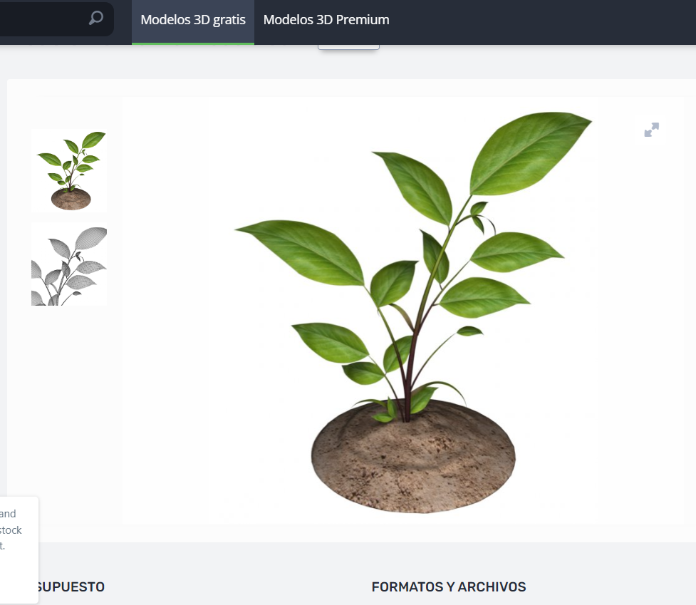
Fourth
I explored some free 3D model web pages to find a small plant, because before that i simulated it only with organic geometries.
This is the web page: https://free3d.com/
Fifth
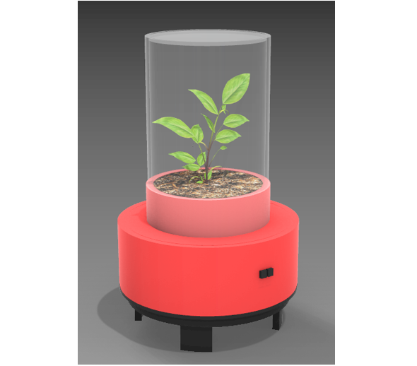
The perspective view in Rhino looks very good, but just to explore the render settings, I'm going to assign materials and colors to the model.
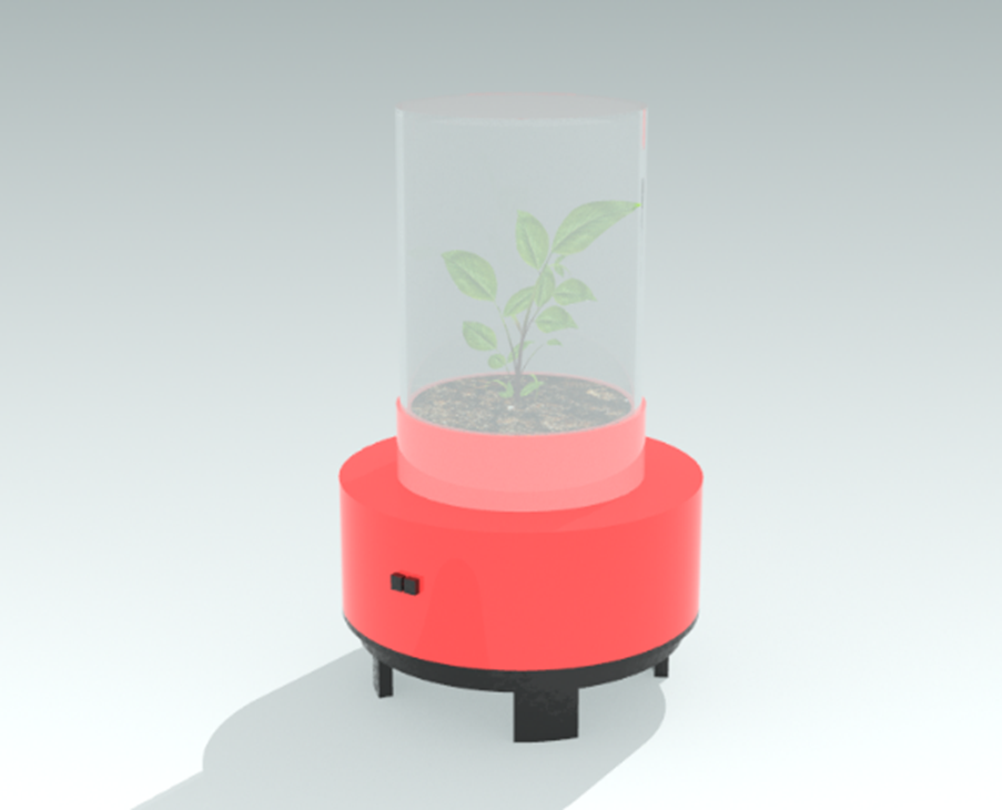
Last step
I finally made a couple or renders, now is time to learn from zero with SolidWorks.
Next I will document everything I did in SolidWorks:
I looked for several tutorials and this is the best one I found, is in Spanish but is easy to follow even with no sound . I'm going to follow it and document my learning process from it.
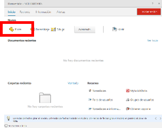
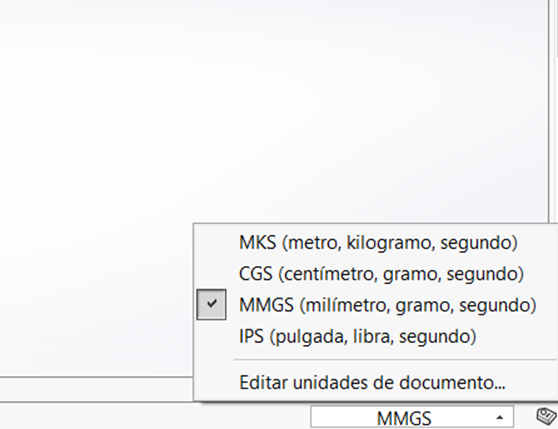
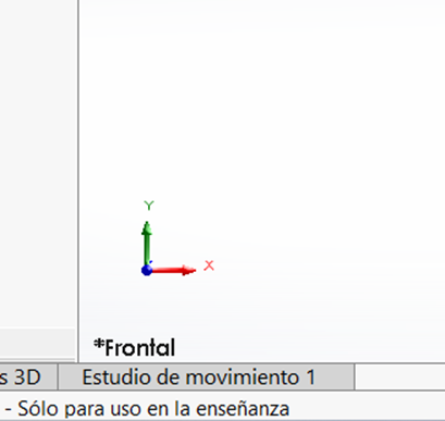
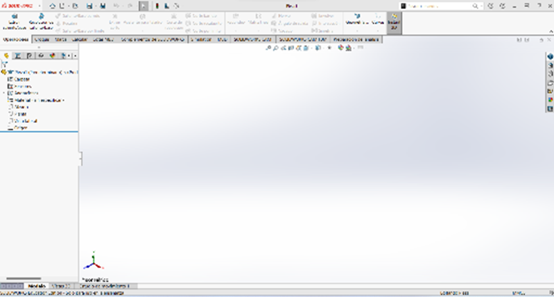
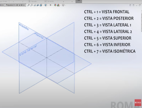
First, I have to select the type of drawing "pieza" and then the units "MMGS" in the bottom right corner. In the bottom left corner, shows the default view by the software "front" (top in English). I'm going to change it to isometric by typing "CTRL 7".
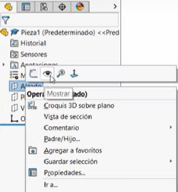
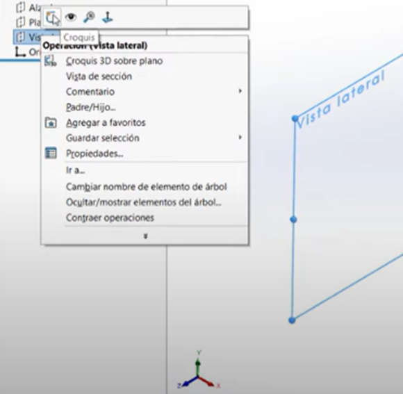
Now all the views are hidden and you have to show them in the view by right clicking on the name of each one and selecting the eye icon at the top.
Then tree important points to manipulate the working view: if yo want to rotate, press and hold the scroll and move the mouse, if you only want to pan de view, hold CNTRL and the scroll, and other big difference between other softwares is when you what to zoom out or zoom in, to zoom out you must scroll up and to zoom in scroll down.
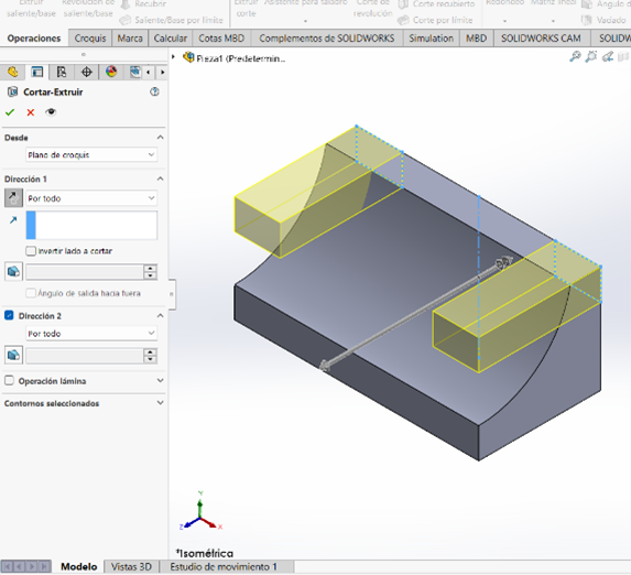
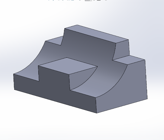
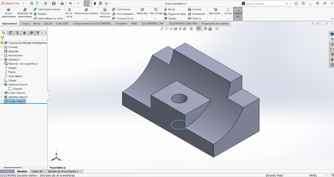
This is the exercise I am trying to do following the tutorial:
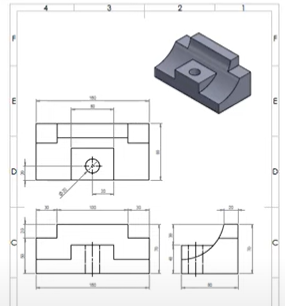
An hour and a half later, I finally finished 😅🎉🥴


Now is AutoCAD time
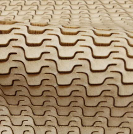
As I said before, i am drawing the dome in 2D. For the final prototype, I think I'm going to use a sheet of transparent acrylic 3 millimeters thick, and make cuts on it that will help for air circulation. I would like to make some kind of scales, similar to the image below.
Once the acrylic is cut, I would have to make a mold to bend the acrylic by thermoforming until it is cylindrical. To prevent the dome from opening, I will put some slots in the lid that will work as assemblies, the same in the bottom part with the pot.
Next I'm going to work with the Rhino model dimensions:
Symbology:
Red lines: guide or projection lines (invisibles/locked for laser machine)
White lines: Geometry lines (cut for laser machine)
What I did was to measure the length of the circumference of the dome to make the development of the cylinder, taking into considerations its upper cover dimension plus an outside offset to be able to use the slots/rectangular cuts as support assemblies.

2.3 Personal conclusions
I feel confident using AutoCAD, it really wasn't complicated for me to make the drawing, although it was a challenge to get the measurements from a three-dimensional geometry. With Vizcom I learned that a big part of the success in obtaining a good render is in writing a good prompt.
On the other hand, I did not feel comfortable working in 3D with any of the softwares, the knowledge I have of Rhino in 3D is very basic and I had never worked at SolidWorks. However, I think that all of them can be useful for different project processes. So I will have to learn to use them to generate the 3D pieces.
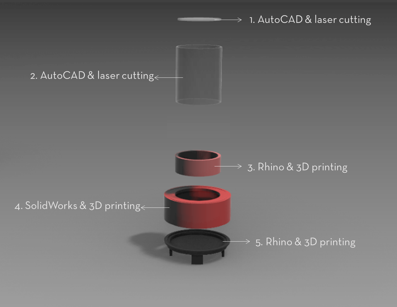
After analyzing the advantages and disadvantages of each, I have decided to use them all for the following parts of my model
Top lid. I will draw the top cover of the dome in AutoCAD considering 3 millimeter acrylic and as shown in the AutoCAD drawing, I am considering making some rectangular cuts that will work as support assemblies for the dome. I think tha AutoCAD will be an excellent tool for all the flat & laser cut pieces of my project. It is very easy for me to work with it, and once I have these drawings complete, I will be able to dedicate more time to the other pieces that are more complicated.
Dome. I will also draw it in AutoCAD considering a 3 millimeter acrylic, and as shown in the image above, i am going to make some cuts with the laser cutting machine to help air circulation, and to get the cylindrical shape I am using a mold and heat.
Growing pot. As it is one of the simplest pieces of the project, I will design it in Rhino because it is the software I use best and I'm going to print it in 3D.
Expandible pot. This could be the most complex piece of all the project, because the soil for the plant, all the electronics and the rotating system will be concentrated inside the pot. So, for sure, this peace is going to be In a constantly changing. I think de best i can do is to draw it in a parametric software such as SolidWorks.
Draining plate. I will draw this in Rhino because it is a simple piece, that does not requires so much precision and apparently will not need big changes. I'm also going to print this one in 3D.