Assignments
1. Principles and practices
2. Project management
3. Computer Aided design
4. Computer controlled cutting
5. Electronics production
6. 3D Scanning and printing
7. Embedded programming
8. Computer controlled machining
9. Electronics design
10. Output devices
11. Input devices
12. Molding and Casting
13. Networking and communications
14. Interface and application programming
15. Wildcard week
16. System integration
17. Applications and implications
18. Invention, intellectual property and income
19. Project development
9. Electronics design
Assignment:Group assignment:
Use the test equipment in your lab to observe the operation of a microcontroller circuit board
Individual assignment:
Use an EDA tool to design a development board to interact and communicate with an embedded microcontroller, produce it, and test it
Design
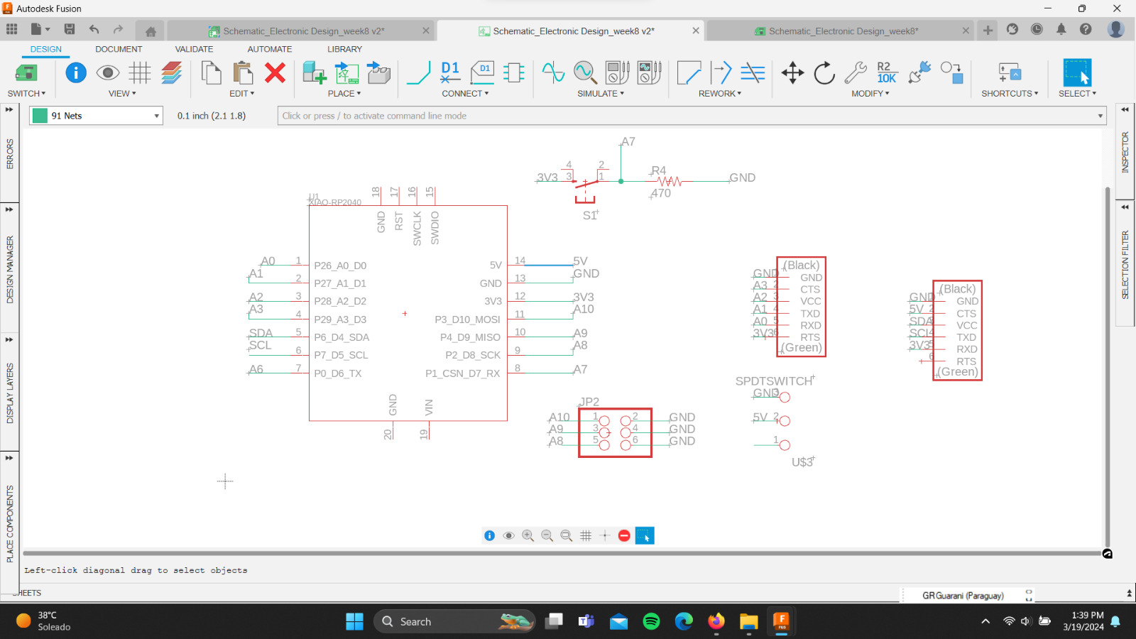
Due to my limited knowledge of electronics, and although I have tried to understand how to use the main types of components, I realized that in this short time I was not going to be able to design a PCB from scratch. For this reason, I decided to replicate the Fab-Xiao in order to learn how to use the EDA (Electronic Design Automation) tools.The first step was to download the Fab-Xiao Schematic + Board file. The software I used was Fusion 360 - Eagle. I imported the .sch file to analyze the components of the board and their connections.
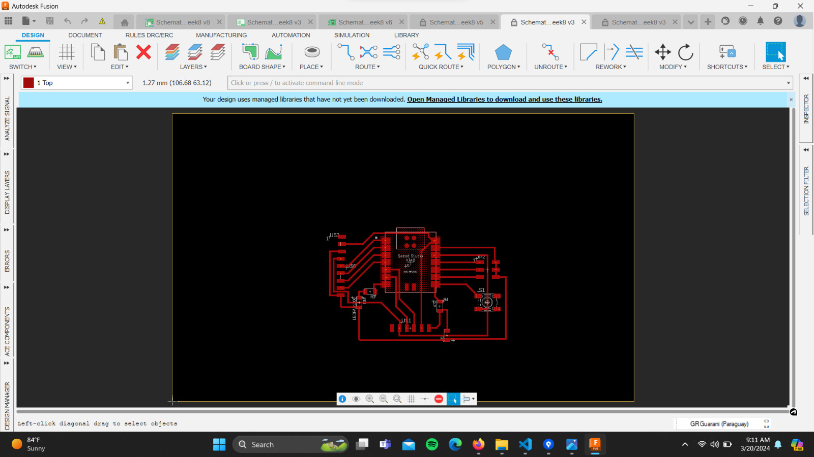
Next, I clicked on "switch to a PCB document" and started organizing the components, following the layout of the Fab-Xiao. Throughout the process, I used the following video tutorial as a guide.
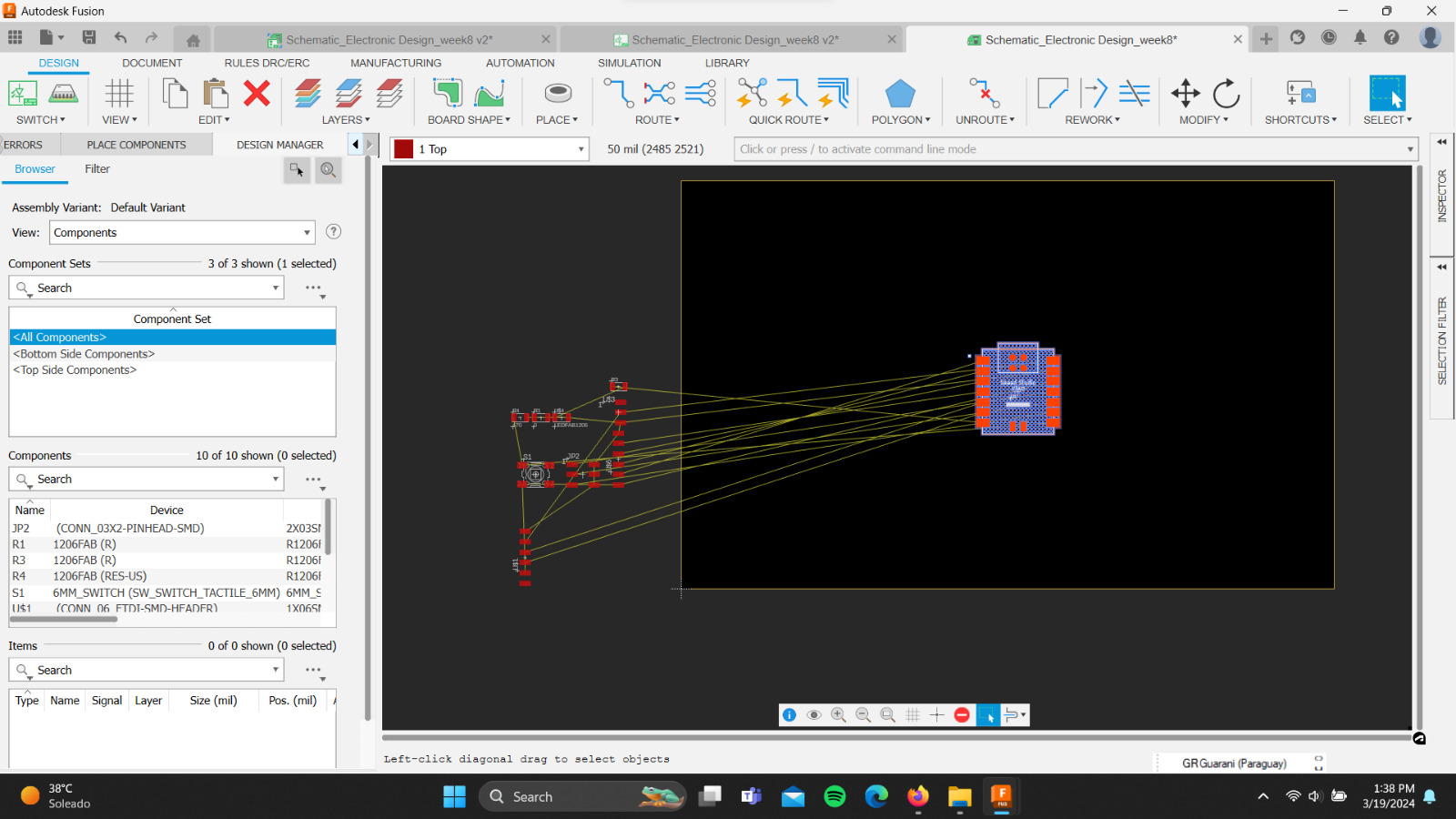
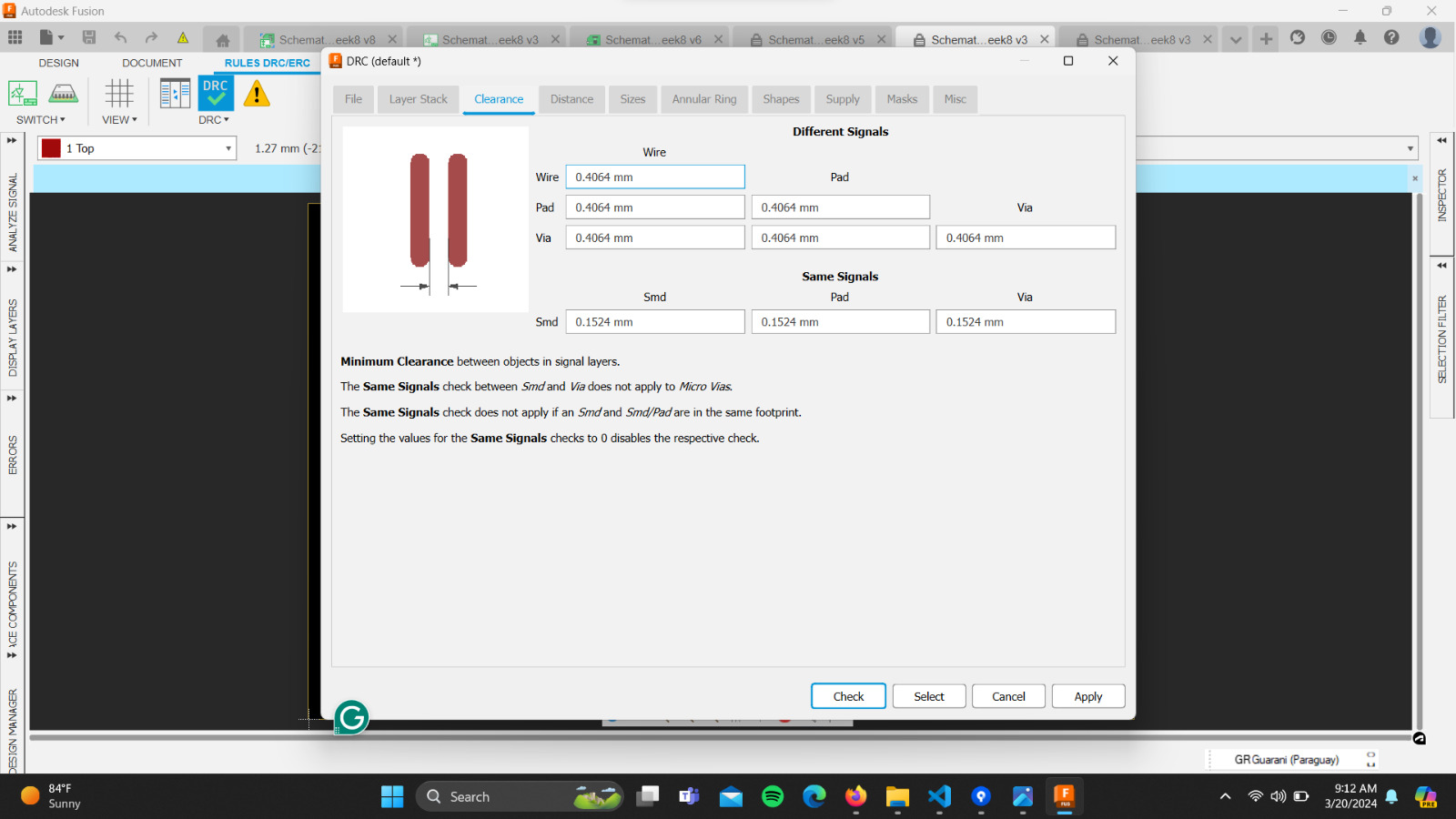
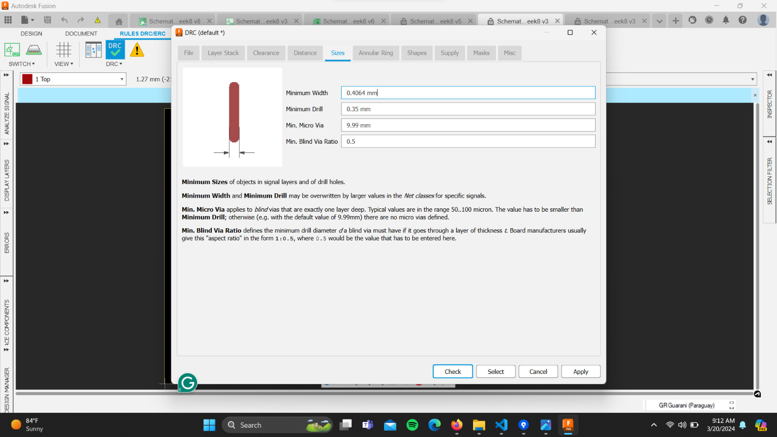
Before starting to route the different components, I configured the various parameters in the "DRC" section. Then, by observing the images of the Fab-Xiao, I started routing the board, attempting a similar design.
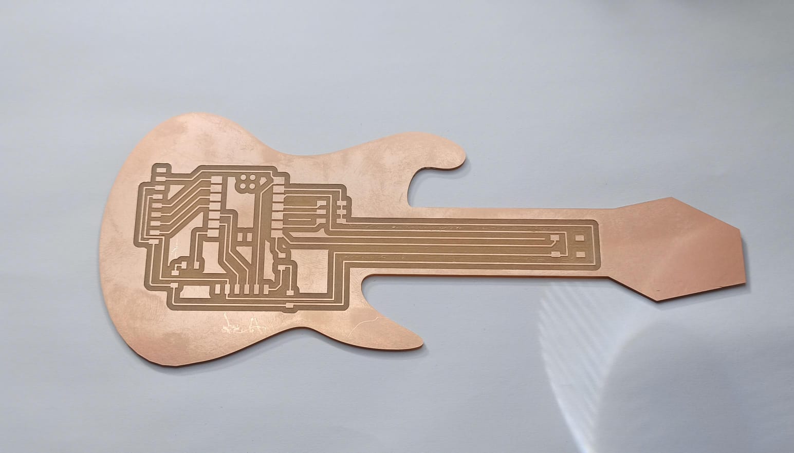
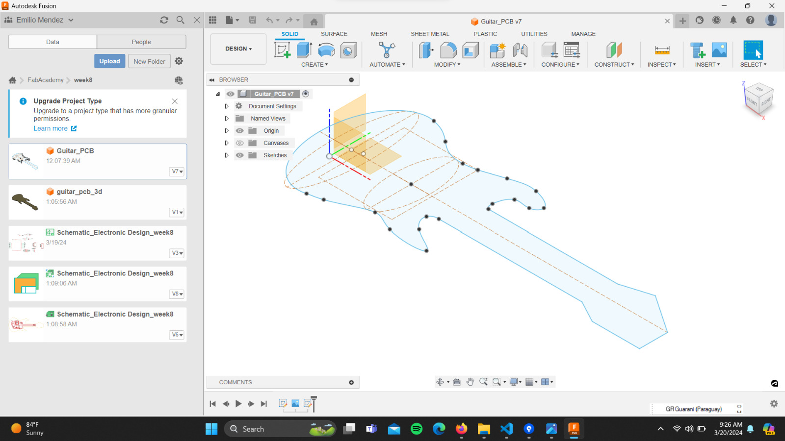
These steps led me to understand a little more about the use of EDA, so I decided to take a bit more of a risk and transform the Fab-Xiao into a guitar-shaped board called "Fab-Xiao-Guitar". To do this, I followed this video tutorial, and using the design skills I had already acquired in Fusion 360, I designed the guitar.
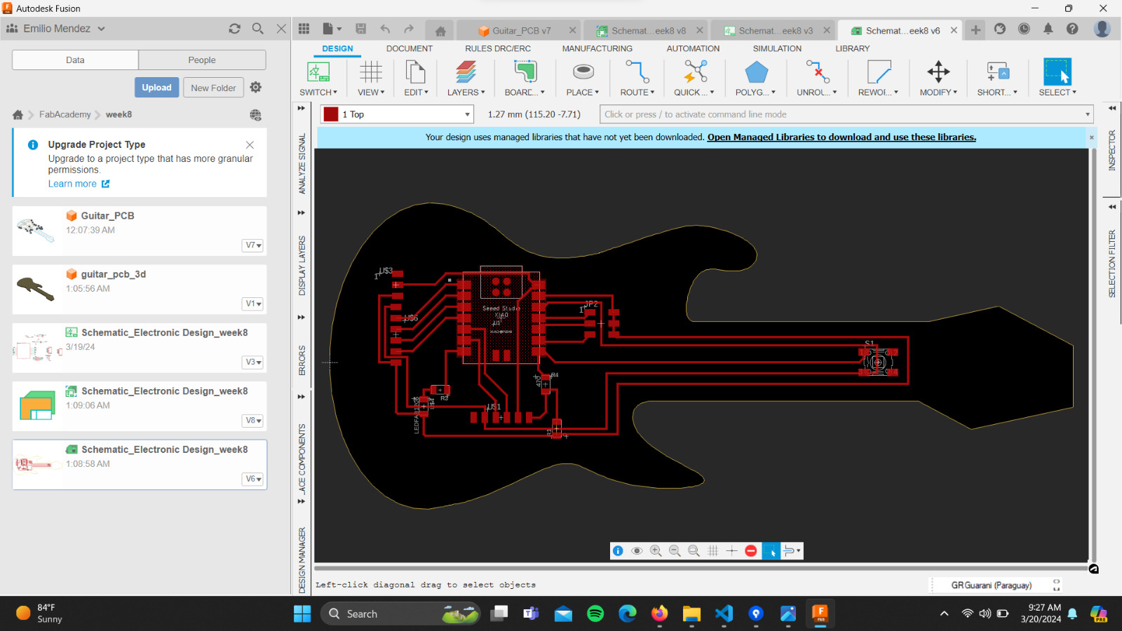
Finally, clicking on the Manufacturing section, I generated the Gerber files to be able to manufacture the board. At this point, we encountered two problems. Due to the intense heatwave in Paraguay, and consequently the prolonged use of air conditioning, we experienced constant and prolonged power outages throughout the week, so we were unable to use the machinery in the lab. Additionally, currently at the University, we are in an academic and administrative pause due to some political decisions. Our work is still in progress...
Milling Process
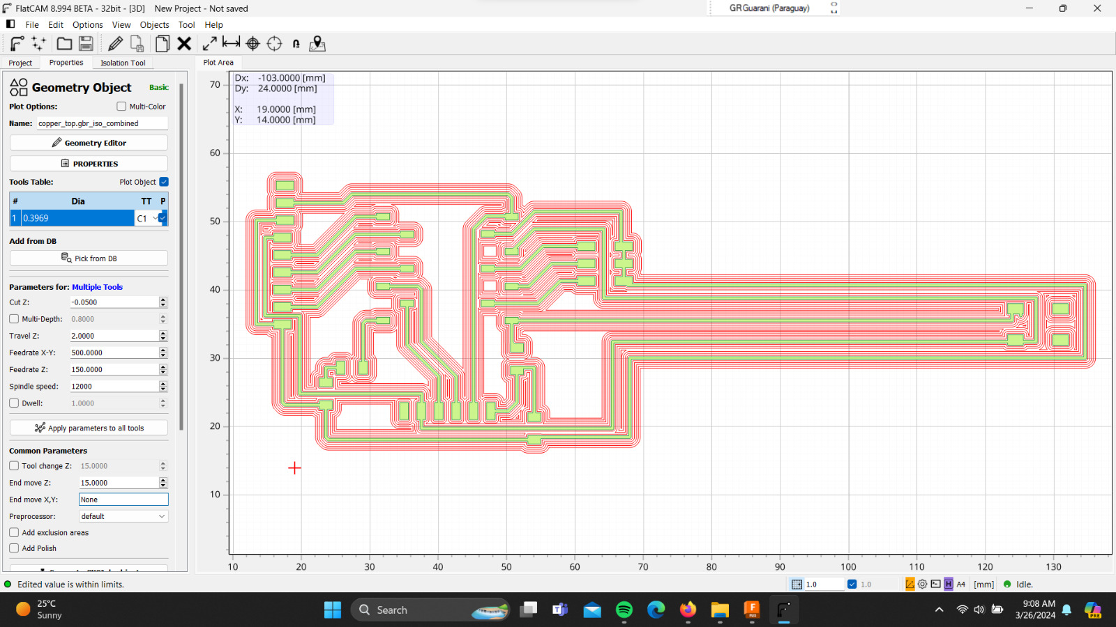
After a week of constant power outages that prevented us from working, I finally managed to build my board. The parameters for milling were as follows:For the trace I used:
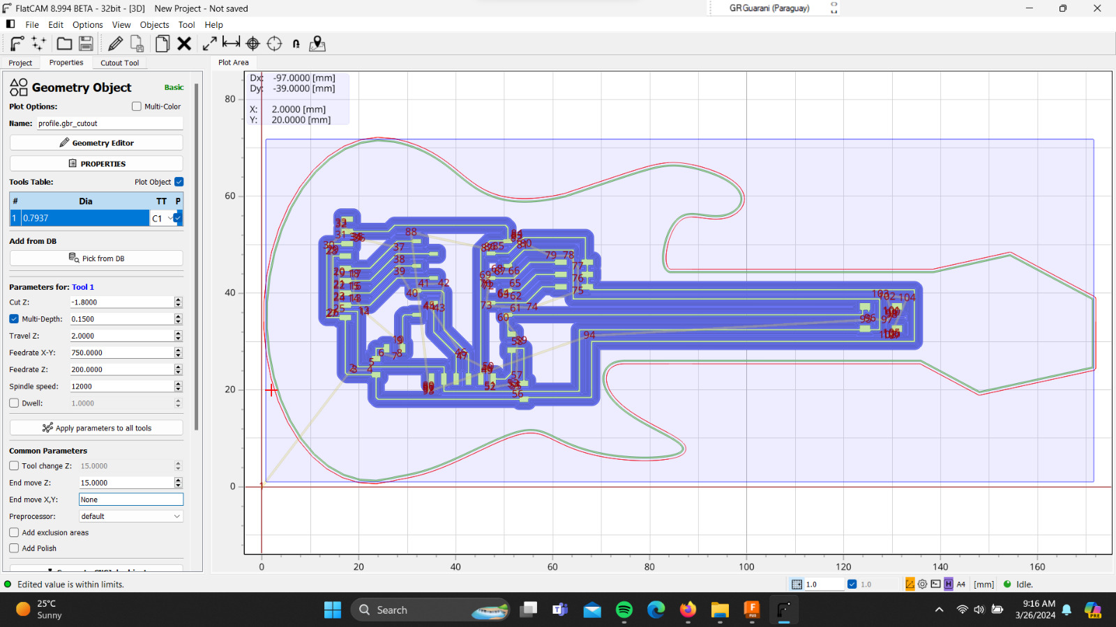
Next, I configured the parameters for the cutout:
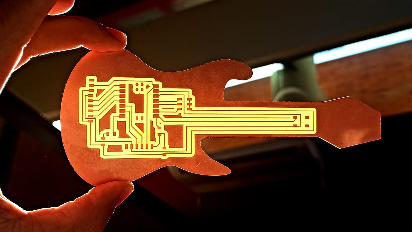
I used the Roland MODELA Pro II MDX-540 to milling the board and this was the result: