Assignments
1. Principles and practices
2. Project management
3. Computer Aided design
4. Computer controlled cutting
5. Electronics production
6. 3D Scanning and printing
7. Embedded programming
8. Computer controlled machining
9. Electronics design
10. Output devices
11. Input devices
12. Molding and Casting
13. Networking and communications
14. Interface and application programming
15. Wildcard week
16. System integration
17. Applications and implications
18. Invention, intellectual property and income
19. Project development
5. Electronics production
The Design
As every week, all activities and definitions are new to me. The most experience I have with electronic boards is having soldered some loose wires on my mom's Christmas lights board and having soldered the jack input of my Boss GT100 effects pedal.So, like every week, my main goal is to learn the basic foundations and skills proposed for the week. To achieve this, I used the QT electronic board design. In our particular case, the design is an adaptation of version 2 found in the repository because one of our components is bigger.
As a first step, we imported the gbr file from QT into the FlatCam software. The design was placed in the positive quadrant at a distance of 1 mm from the x and y axis.
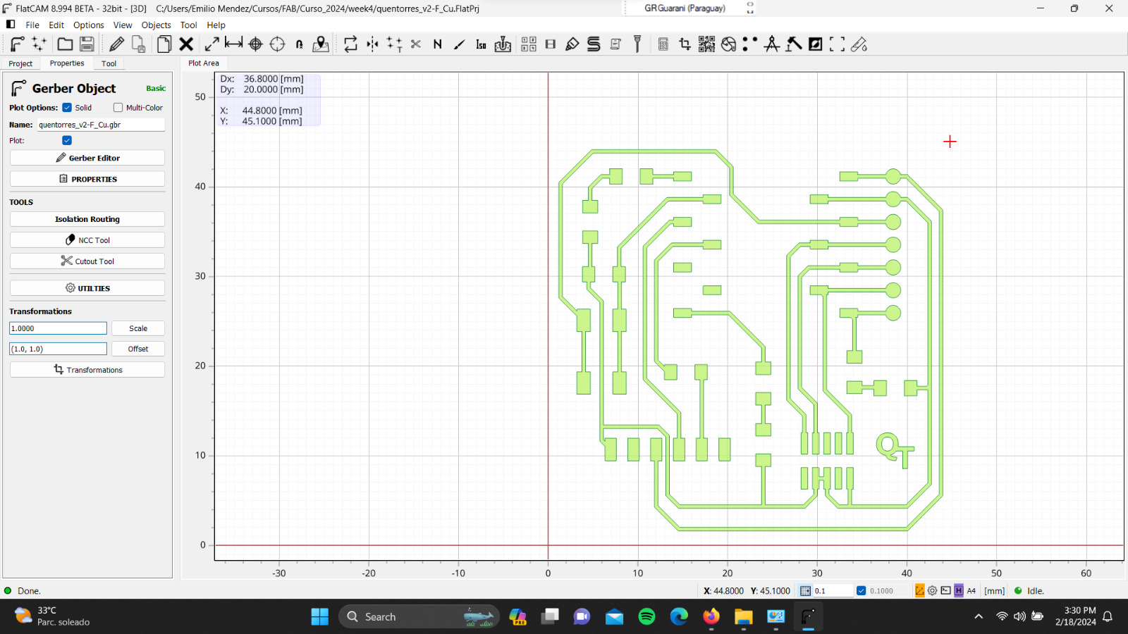
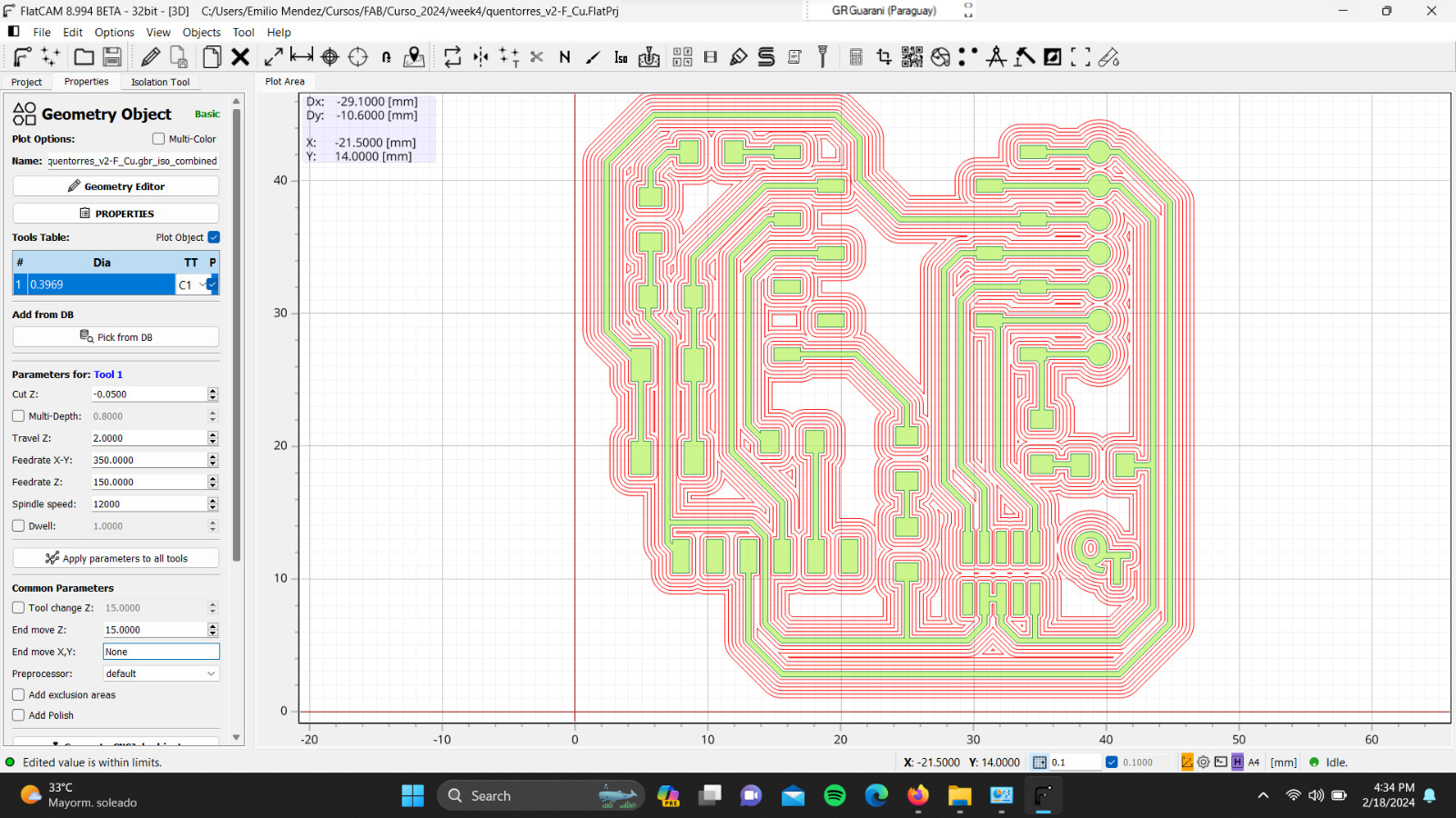
This file corresponds to the trace design, meaning it is used to create the circuit on the electronic board. Afterward, various parameters for milling were specified:
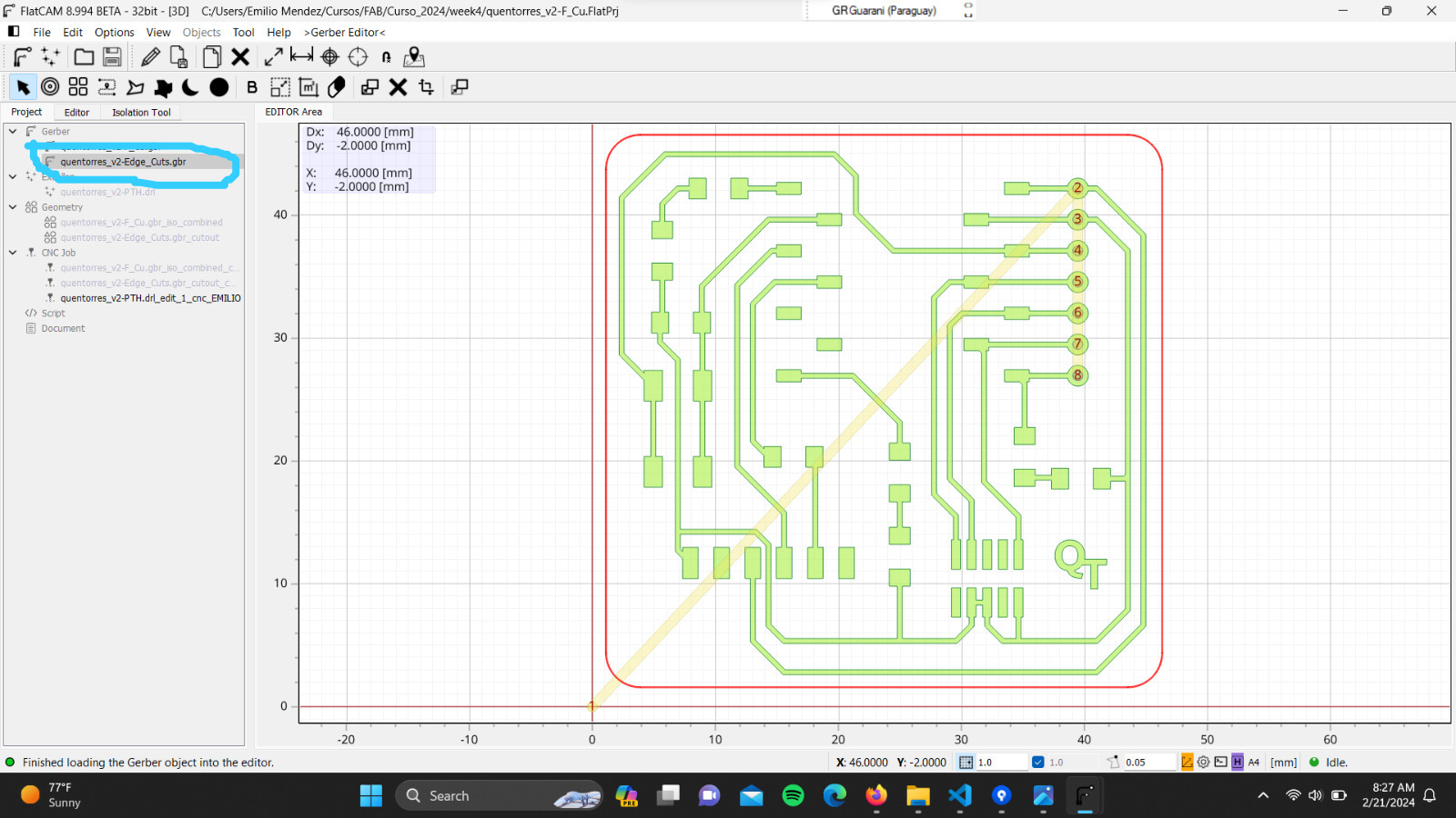
Next, we configured the parameters for the cutout using the gbr file "quentorres_v2-Edge_Cuts":
Finally the CNC code was saved to use it in the milling machine
Milling Procedure
The milling machine we used was the "Roland MODELA Pro II MDX - 540"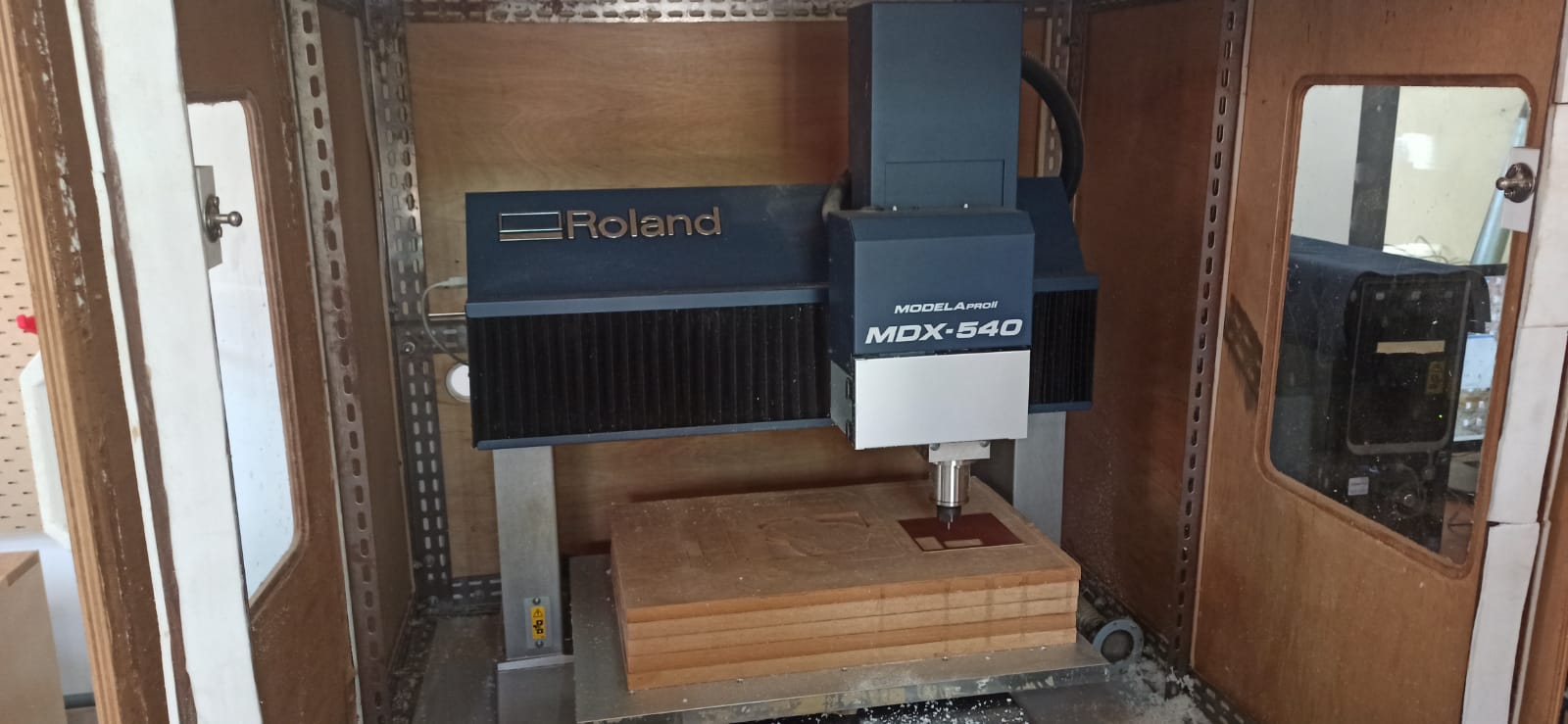
After turning on the machine and opening the "V Panel A Pro II" software, we placed a blank FR1 electronic board on the sacrificial bed using double-sided adhesive tape. The next step was to set the origin, where the x and y axes were configured manually, while the z-axis was configured using a sensor as demonstrated in the video.
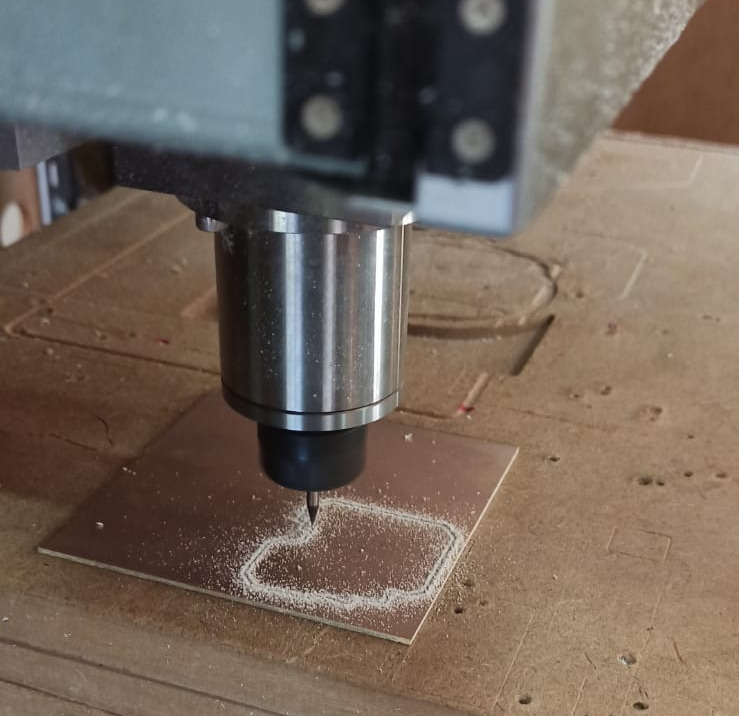
Here is a photo during the milling.
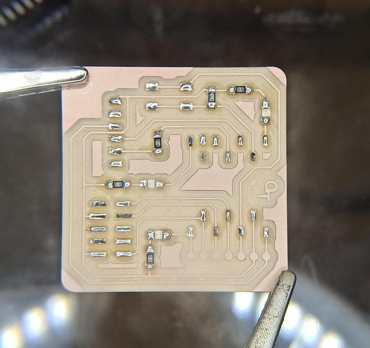
This is the final result.
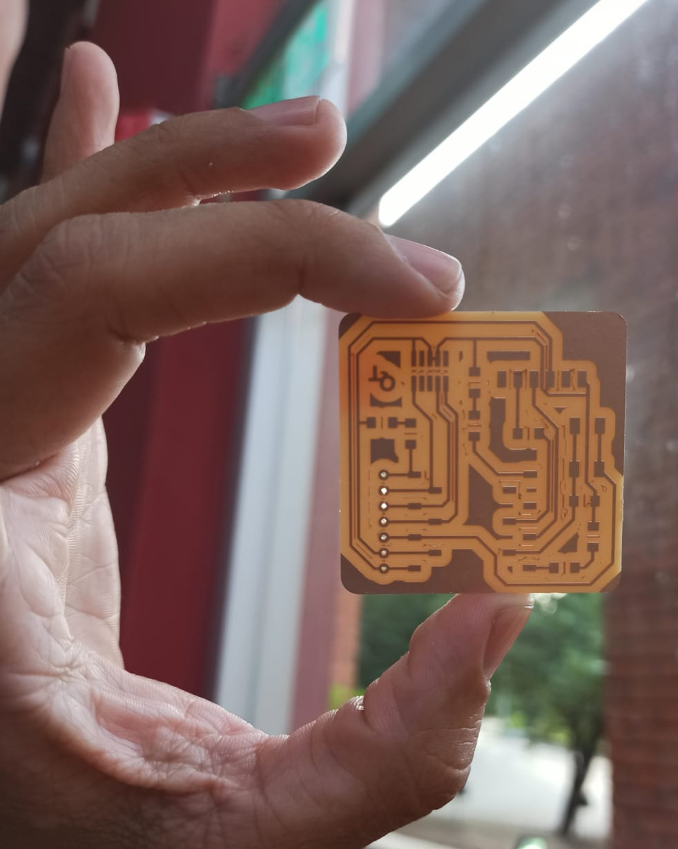
Note: the design we finally used is a bit different, as we had to make some changes due to component compatibility. So we went back and made another board.
Assembly
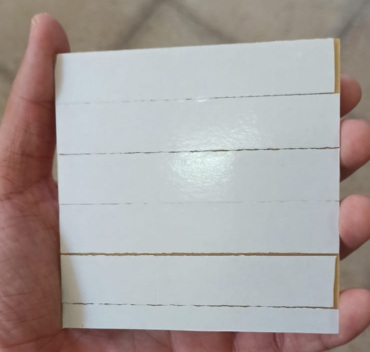
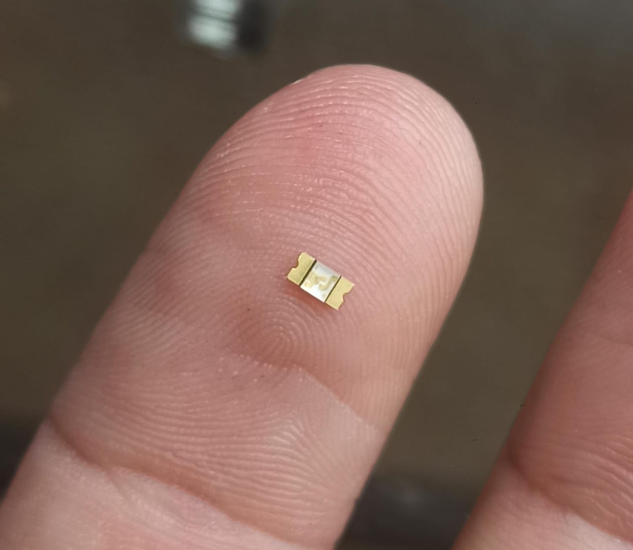
To assemble the board we use the components mentioned in the repository.Before starting to solder the QT board, I practiced soldering on other unused boards, applying the various techniques taught by my mentors. Once I gained confidence, I began by soldering the smaller components: the micro-LEDs and resistors.
After soldering the larger components the final result was as follows:
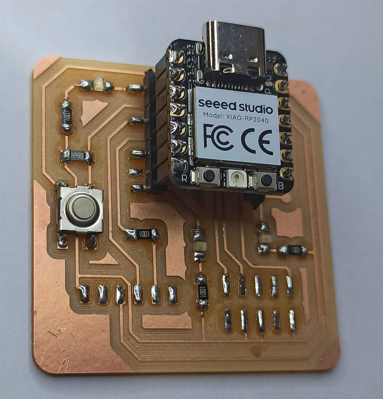
I was very satisfied with my work.
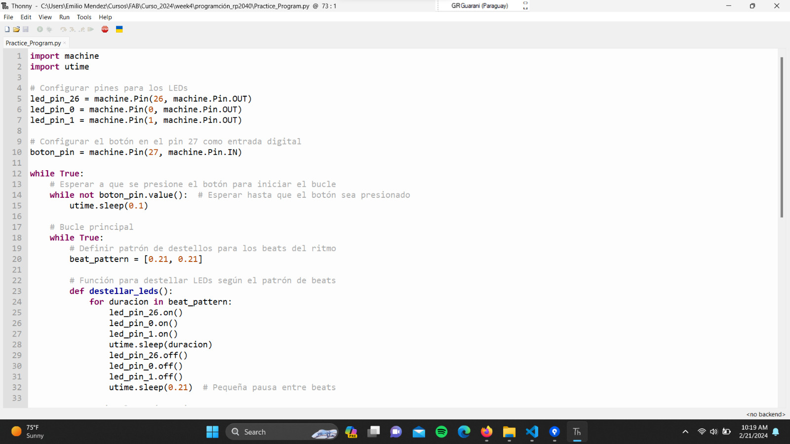
Programming
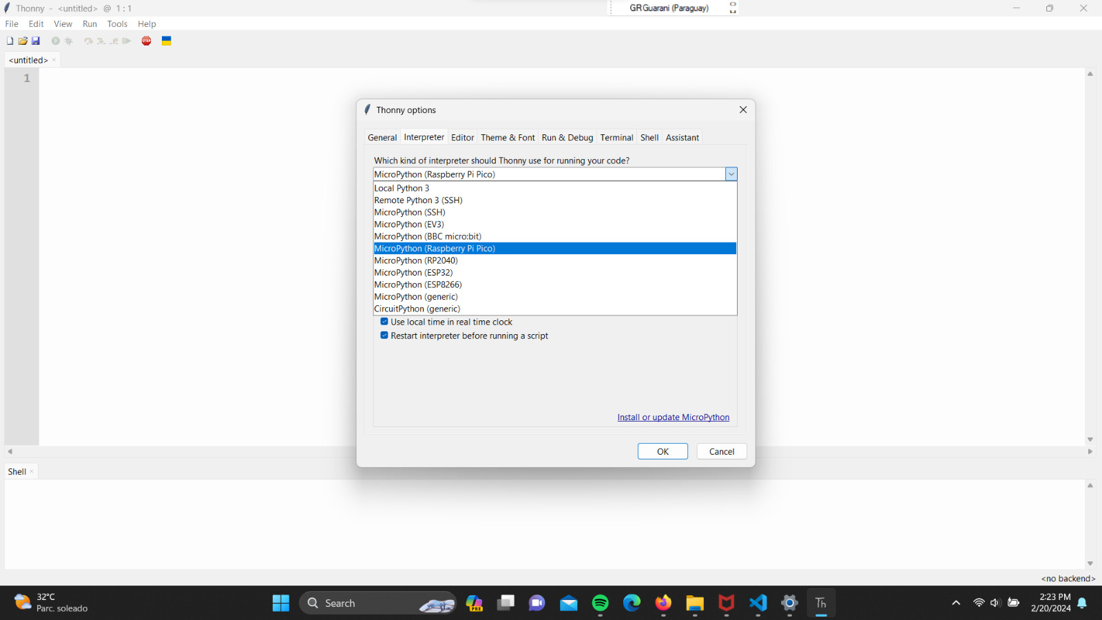
To begin programming, I utilized the assistance of ChatGPT. First, I asked directly how to start programming a Xiao-RP2040 microcontroller and followed the steps it provided. At the same time, it informed me about various computer terms that I wasn't familiar with in depth. Also, I downloaded and installed Thonny as a code editor.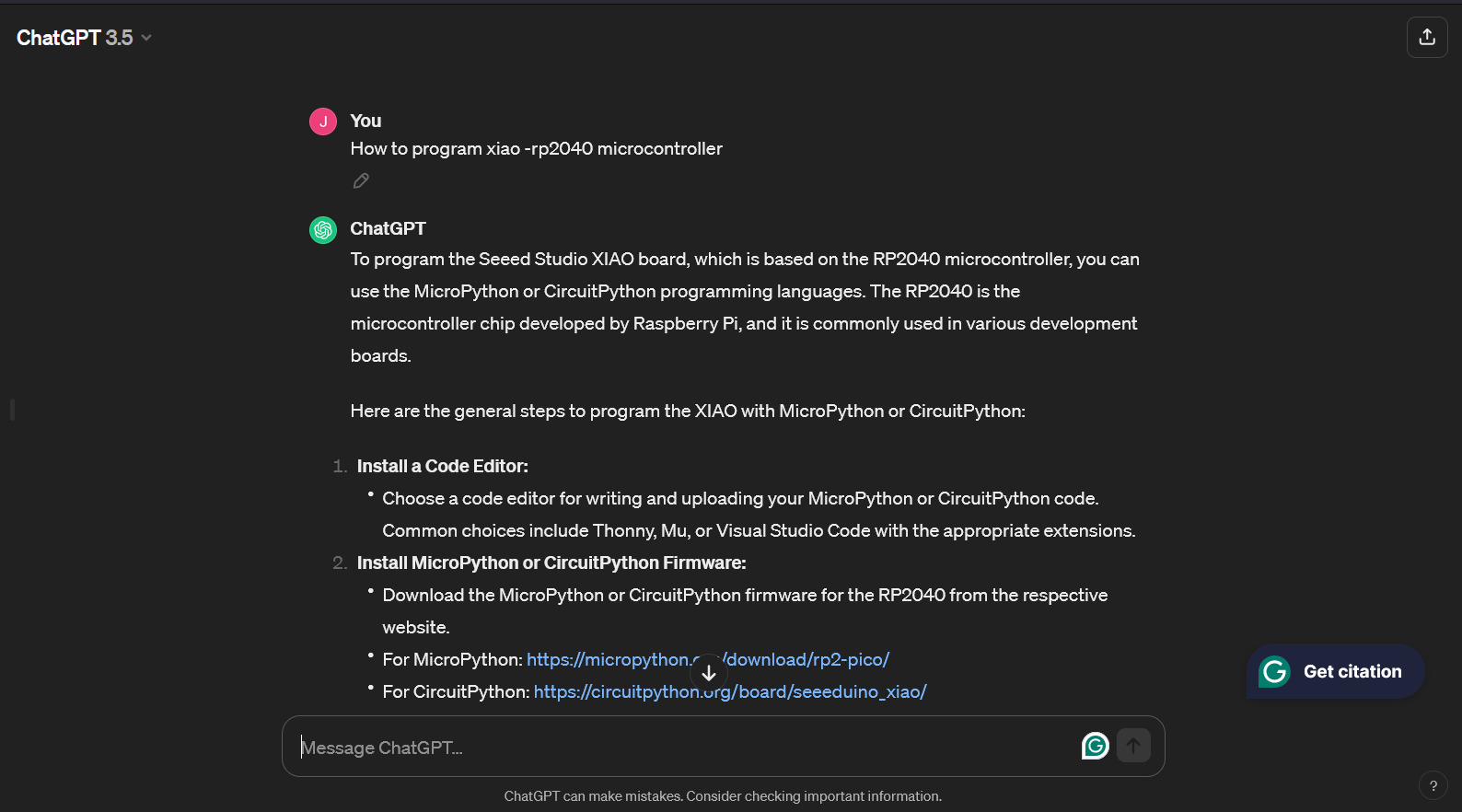
Because I lack experience in programming, I turned to ChatGPT again to code some lighting patterns for the LEDs. After generating the code, I edited it to my liking. To be honest, I tried to synchronize the LEDs with AC/DC's song "Thunderstruck," but I couldn't achieve it. After reading more about it, I understood that there are special components that allow for more precise control of the beats per minute (BPM). Despite coding the corresponding BPM for the song, I couldn't achieve perfect synchronization. The final result of my programming is shown in the following video.