Assignments
1. Principles and practices
2. Project management
3. Computer Aided design
4. Computer controlled cutting
5. Electronics production
6. 3D Scanning and printing
7. Embedded programming
8. Computer controlled machining
9. Electronics design
10. Output devices
11. Input devices
12. Molding and Casting
13. Networking and communications
14. Interface and application programming
15. Wildcard week
16. System integration
17. Applications and implications
18. Invention, intellectual property and income
19. Project development
10. Output devices
Assignment:Group assignment:
Measure the power consumption of an output device
Document your work (in a group or individually)
Individual assignment:
Add an output device to a microcontroller board you've designed and program it to do something
Planning
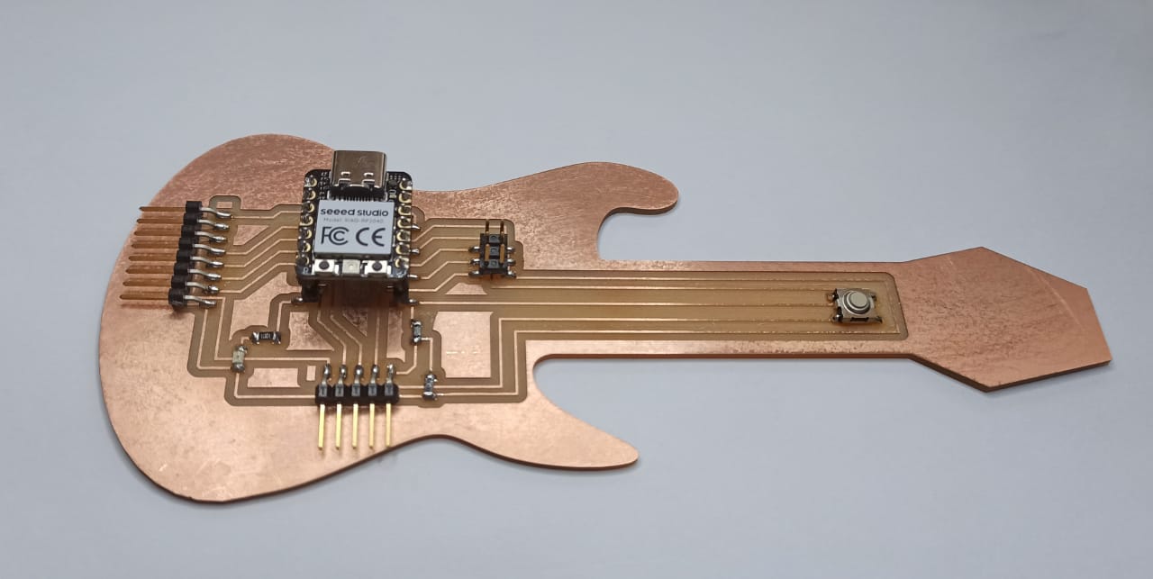
I decided to use the board I designed during the "Electronics Design" week, which is a Fab-Xiao shaped like an electric guitar. It only has a minor change in the footprint of the Xiao RP2040, to be able to use a connector that allows me to remove and insert the Xiao. This way, the microcontroller can be reused in different assignments. The Gerber files of the design are available in the downloads section.Here are the parts:
- 1 Seeed Studio XIAO RP2040
- 1 Red LED SML-LX1206IC-TR
- 1 0Ω resistor
- 1 499 Ω resistor
- 1kΩ resistor
- Button
- 2 male horizontal header
- 1 male vertical header