1. Principles and practices
2. Project management
3. Computer Aided design
4. Computer controlled cutting
5. Electronics production
6. 3D Scanning and printing
7. Embedded programming
8. Computer controlled machining
9. Embedded programming
10. Mechanical Design
11. Input devices
12. Molding and Casting
13. Networking and communications
14. Interface and application programming
15. Wildcard week
16. System integration
17. Applications and implications
18. Invention, intellectual property and income
19. Project development
13. Networking and communications
Assignment:Group assignment:
Send a message between two projects
Individual assignment:
design, build, and connect wired or wireless node(s) with network or bus addresses and local input &/or output device(s)
Planning
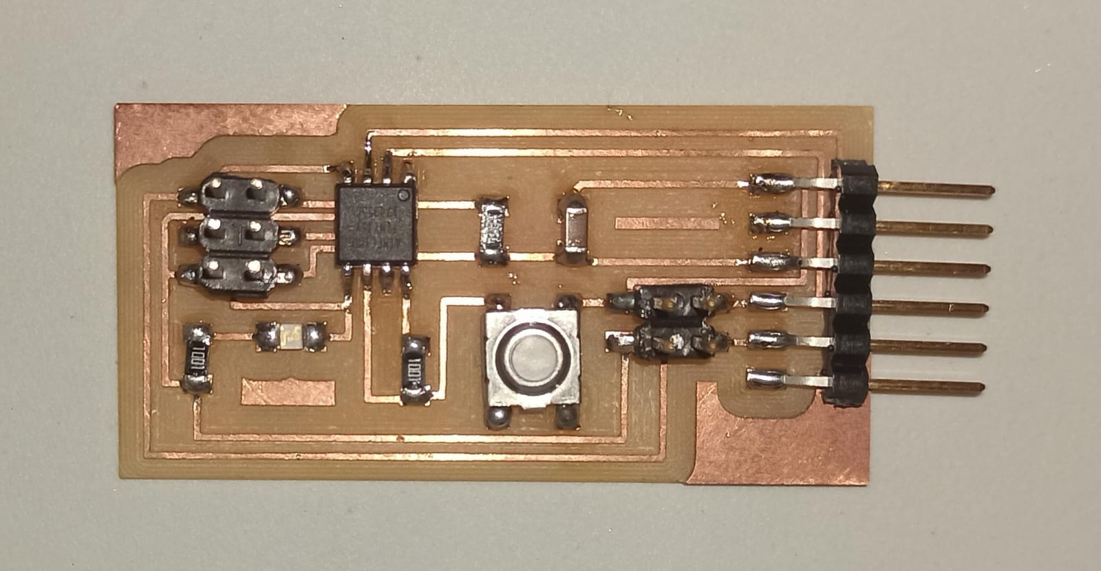
For this week, I decided to design an electronic board and manufacture it twice, with the aim of connecting them through an FTDI cable and controlling them from the computer. The board contains an Attiny 45 microcontroller. Below are the components of the board.This is the finished electronic board
Programming and Testing
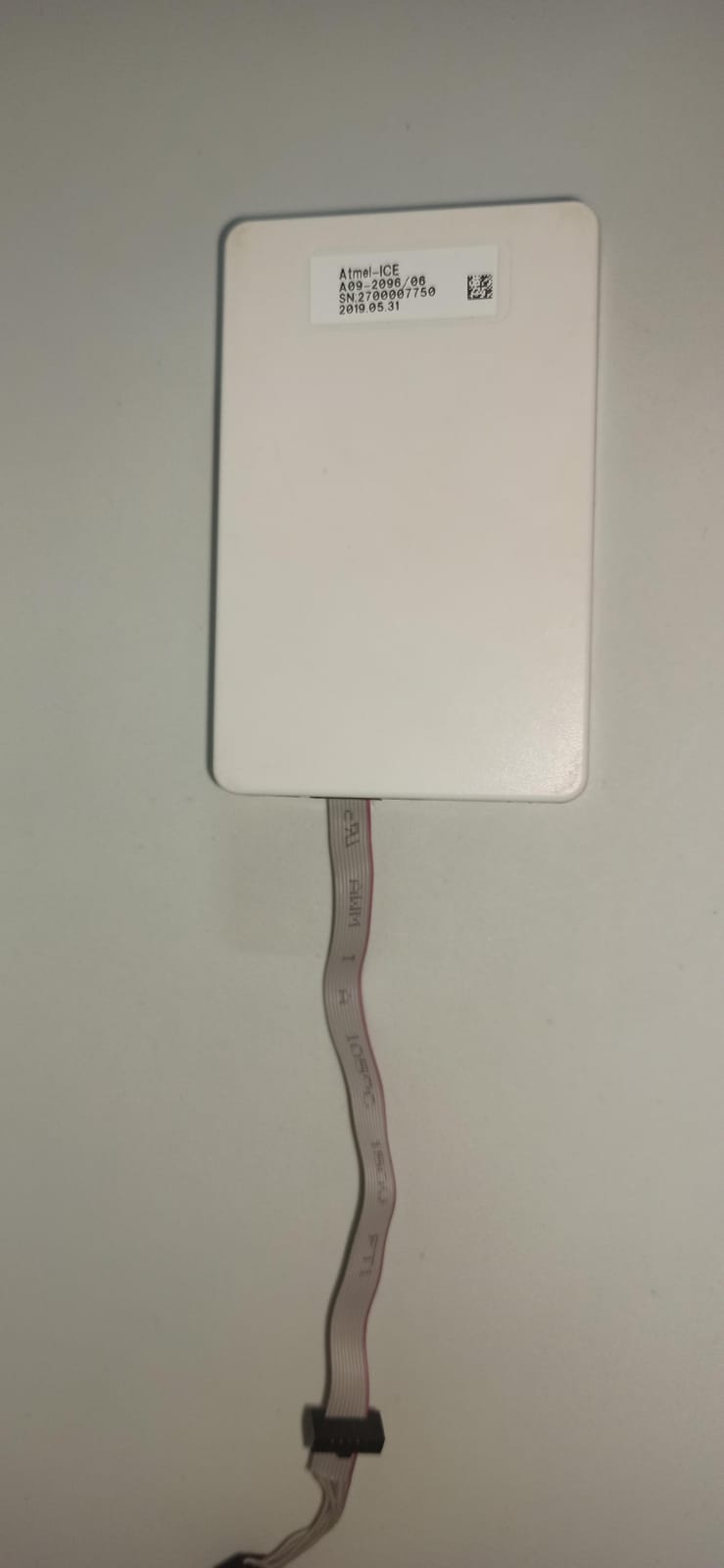
For programming the Attiny45, it's necessary to use a programmer. In this case, I used the Atmel-ICE, which connects to the board through the J1 ISP 2x3 connector.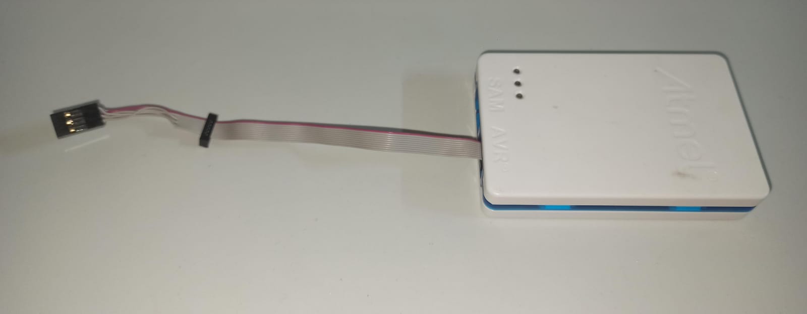
Before starting to program was necessary this preliminary steps:
1. Download version 1.8.18 of the Arduino IDE
2. Download and install the Atmel-ICE driver
3. Install the Attiny45 library by copying and pasting the link "https://raw.githubusercontent.com/damellis/attiny/ide-1.6.x-boards-manager/package_damellis_attiny_index.json,https://github.com/earlephilhower/arduino-pico/releases/download/global/package_rp2040_index.json,https://mcudude.github.io/MiniCore/package_MCUdude_MiniCore_index.json" into the "Additional Board Manager URLs" box, located in File > Preferences.
4. In Tools > Board > Board Manager, search for "attiny" by "David A. Millis" and install it
5. Go to Tools > Programmer and select the option "Atmel-ICE (AVR)"
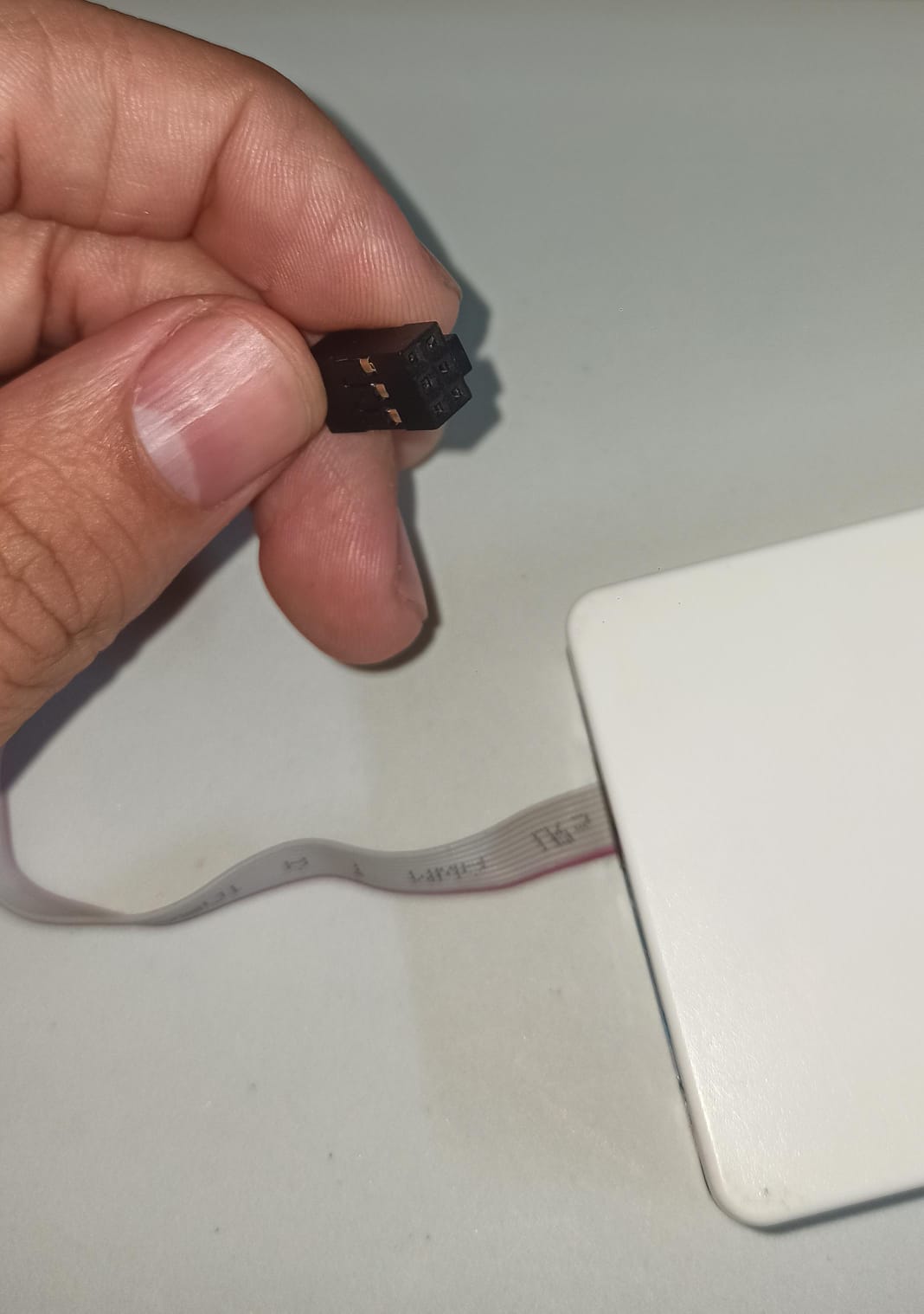
Once these steps are completed, you can start writing the code and programming the board. To program, you should use an FTDI-USB cable to connect the board to a USB port of the computer. At the same time, through the ISP 2x3 connectors of the board, you must connect it to the Atmel programmer, and the Atmel programmer must be connected to another USB port on the computer.
Note: Be careful to ensure that the pins of the FTDI cable correspond to the pins of the board; likewise, ensure that the pins of the Atmel cable match. Refer to the datasheet of the Atmel for this purpose.
To verify the correct operation of the board and the proper connection of the cables,the first thing I did was to use the "Blink" code from the Arduino IDE. In my case, pins 3 and 2 correspond to rx and tx respectively. Once I confirmed the correct operation of both boards, I programmed both boards with the following code.
  #include <SoftwareSerial.h>

  int rx = 3;    //Declares the RX pin
  int tx = 2;    //Declares the TX pin

  SoftwareSerial mySerial(rx, tx);  //Setting up the RX/TX pins as a SoftwareSerial

  char buttonState = '1';//Declares the character that represents the virtual button current state
  char lastButtonState = '0'; //Declares the character that represents the virtual button last state

  int ledPin = 0;     //Declares the pin where the indicator LED is already attached


  void setup(){
    mySerial.begin(9600);       //Start the serial communication and select the its speed that deppends of the frequency that it will be program the attiny

    pinMode(ledPin, OUTPUT);      //Configures the LED pin as an output

  }

  void loop() {

    buttonState = mySerial.read();    //Reads the message a "1" or a "0" from the command line

    if (buttonState != lastButtonState) {   //Checks if there exist a change in the virtual button state

      if (buttonState == '2') {         // Condition For Motor ON

        mySerial.println("ON");         //Prints in the screen the actual state
        digitalWrite(ledPin, HIGH);     //Turns ON the indicator LED


      }
      else if (buttonState == '3'){      // Condition For Motor OFF

        mySerial.println("OFF");         //Prints in the screen the actual state
        digitalWrite(ledPin, LOW);       //Turns OFF the indicator LED

      }

      delay(50);
    }

    lastButtonState = buttonState;        //Sets the current state as a last state

  }
The only difference in the code loaded on one board and the other is in the definition of "buttonState," where for one of the boards, "1" implies turning off the LED and "0" turning on the LED. On the other hand, on the second board, "2" means turning off the LED and "3" turning on the LED. In this way, using the Arduino IDE Serial Monitor, I can interact with both boards simultaneously, as they are connected with cables, as shown in the following video.