Assignments
1. Principles and practices
2. Project management
3. Computer Aided design
4. Computer controlled cutting
5. Electronics production
6. 3D Scanning and printing
7. Embedded programming
8. Computer controlled machining
9. Embedded programming
10. Mechanical Design
11. Input devices
12. Molding and Casting
13. Networking and communications
14. Interface and application programming
15. Wildcard week
16. System integration
17. Applications and implications
18. Invention, intellectual property and income
19. Project development
16. System integration
Assignment:Design and document the system integration for your final project
Block diagram
I was a bit confused about how to start this week's assignment. So I decided to begin by making a block diagram to outline the main parts of my final project. This is a tentative diagram: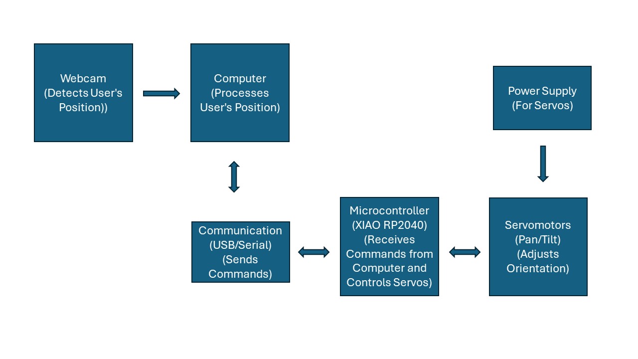
Description
1. Webcam Detects User's Position: - The webcam captures real-time images and sends them to the computer. 2. Processing on the Computer: - The computer analyzes the images to determine the user's position. - It generates commands based on the detected position and sends them to the microcontroller via a USB or serial connection. 3. Microcontroller Receives Commands and Controls Servomotors: - The XIAO RP2040 microcontroller receives the commands from the computer. - It processes these commands and adjusts the servomotors to orient the audio monitors in the correct direction. 4. Servomotor Movements: - The servomotors adjust the pedestal's orientation on two axes (pan and tilt) to point the audio monitors toward the user's position. 5. Power Supply: - Provides the necessary power for the servomotors.Design
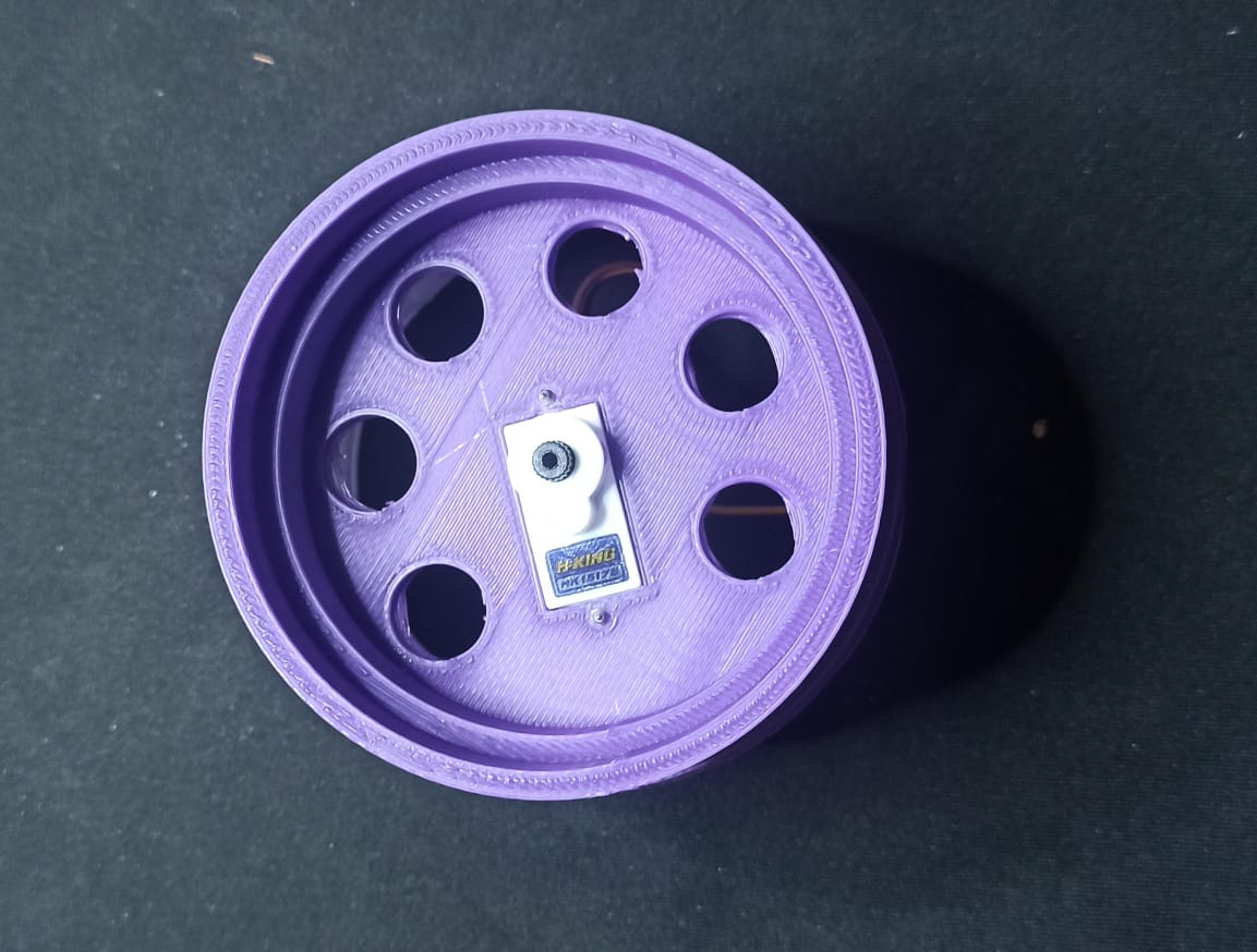
It seemed more convenient for me to start working on the mechanism design. To begin with, since it appeared to be a fairly common mechanism, I looked for designs that I could adapt to my idea. Among these, the pan and tilt movements of a camera are the ones that best fit, so I downloaded a design to start working on it. Using Fusion 360, I adapted the design to use HK15178 servomotors, among other details. This is how it turned out.Testing
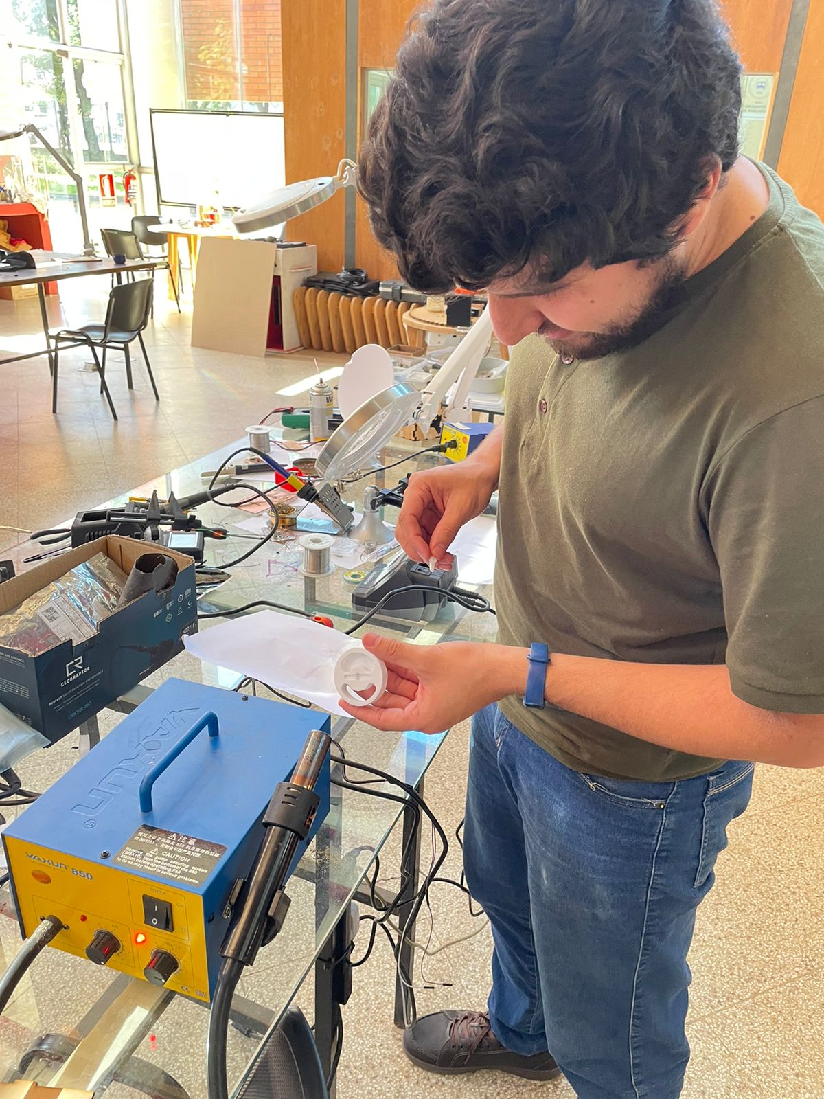
I had many doubts about the design and the mechanism that I could only address by conducting tests. For example, the use of a bearing for the pan movement (I wasn't sure if it was necessary), how the different parts would fit together considering the measurements I used (this was my main concern), among others. Considering this, I decided to print some parts and test the mechanism.
My major issues were with the fitting of the parts. Some parts had very tight measurements and didn't allow me to assemble them, so in the next design, I'll need to add an error factor of 0.5 to 1 mm depending on the part. For now, I used heat to fit the pieces together and test the mechanism. Also, for the next design, I'll need to change the servo mount used for the pan movement. The way it was designed doesn't allow it to fit due to the presence of the cable. Meanwhile, to test the mechanism, I solved it differently.
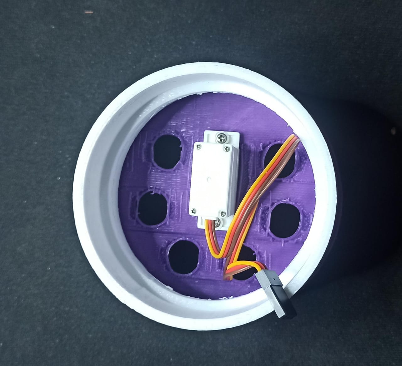
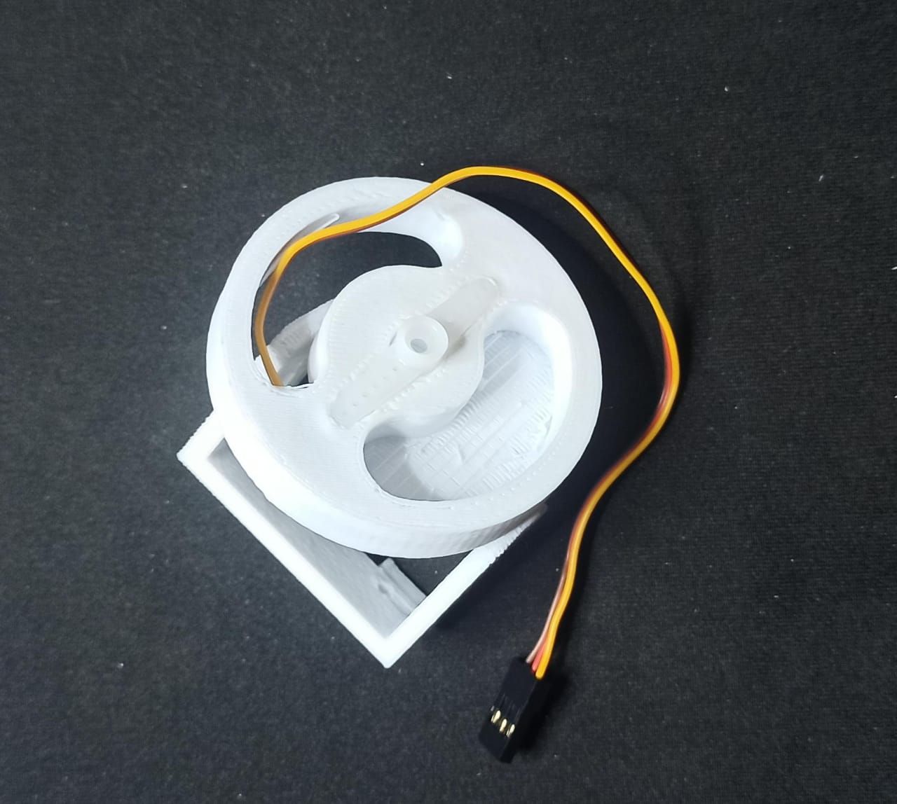

During the assembly, I realized that integrating a bearing into the mechanism will not only improve the performance of the servo responsible for the pan movement (as the weight will not be entirely supported by the servo, and the force will only be used for horizontal rotation), but it will also help support the horizontal axis. During the assembly, I noticed that without the bearing, the mechanism would be very unstable.