Computer Controlled Machining (CCM) is a manufacturing process that involves the use of computer numerical control (CNC) machines to perform precise and complex cuts, drills, and milling operations on a variety of materials. CCM typically involves the use of CAD/CAM software to generate toolpaths that can be used by CNC machines to fabricate parts and components.
For this week I have to design and manufacture a PCB that includes a MCU and a milling machine.
What do I want to do?
I love all the outdoor sports and lately I've been going out camping almost every week. One thing I would like to have is a comfortable night light for inside my tent.
The requirements I have for this night light are:
- It should have a way to control the intensity
- There should be a way to set the color to red so it won't hurt my night vision
- As small and light as possible
- It would be desirable to have it's own battery
Selecting the required components
The minimum required components to make this come true are:
1. MCU
I selected the ESP32-WROOM-32D because it has wireless communication so I could add some wireless control to my night light and because its form factor fits pretty well whit my as little as possible requirements
2. The lights
For this case as I want to be able to control the amount of light and its color the obvious choice is the ws2812b. This is because it's a serial LED that enables me to use just one pin from the MCU and simplify the PCB design.
3. The battery
For the battery I just went for one that is small and that I have on hand and this is a 1s Li-Po 1000mAh.
4. Interface
I would love to use a capacitive touch button to actuate the MCU functionality.
Design
To design this PCB I used Fusion 360 and followed this steps:
1. Start a new electronics design
On the top left corner select the folder icon and select create a new electronics design.
2. Create the Schematic
To create a schematic follow this steps:
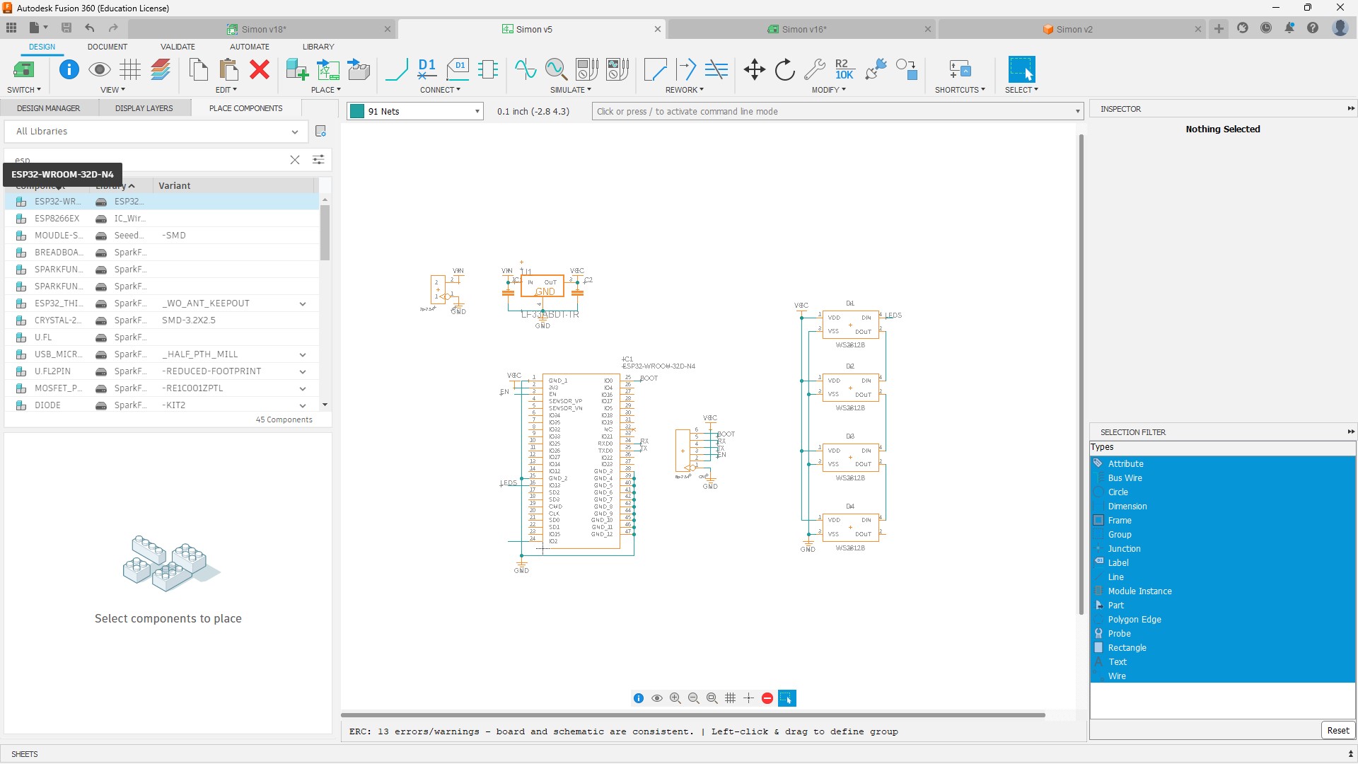
- Select the components you want to use from the library.
- Connect the corresponding wires
- Switch to PCB layout
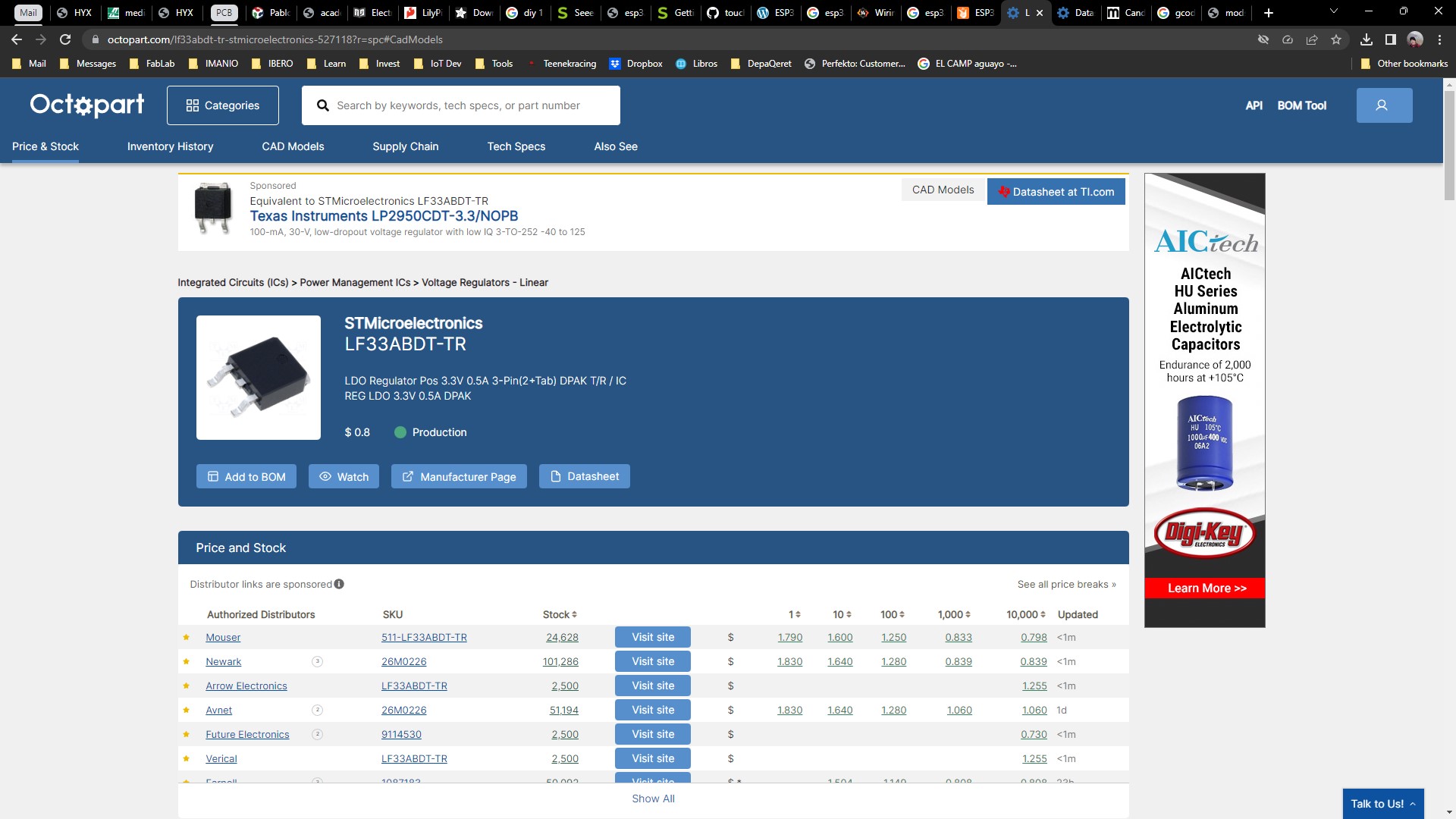
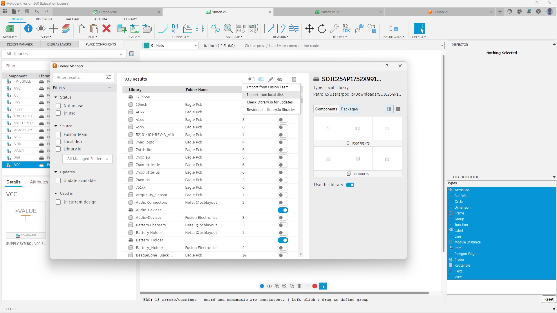
In my case the not all the components where available, so I searched for them in "https://octopart.com/" then I downloaded them and added the corresponding libraries to fusion
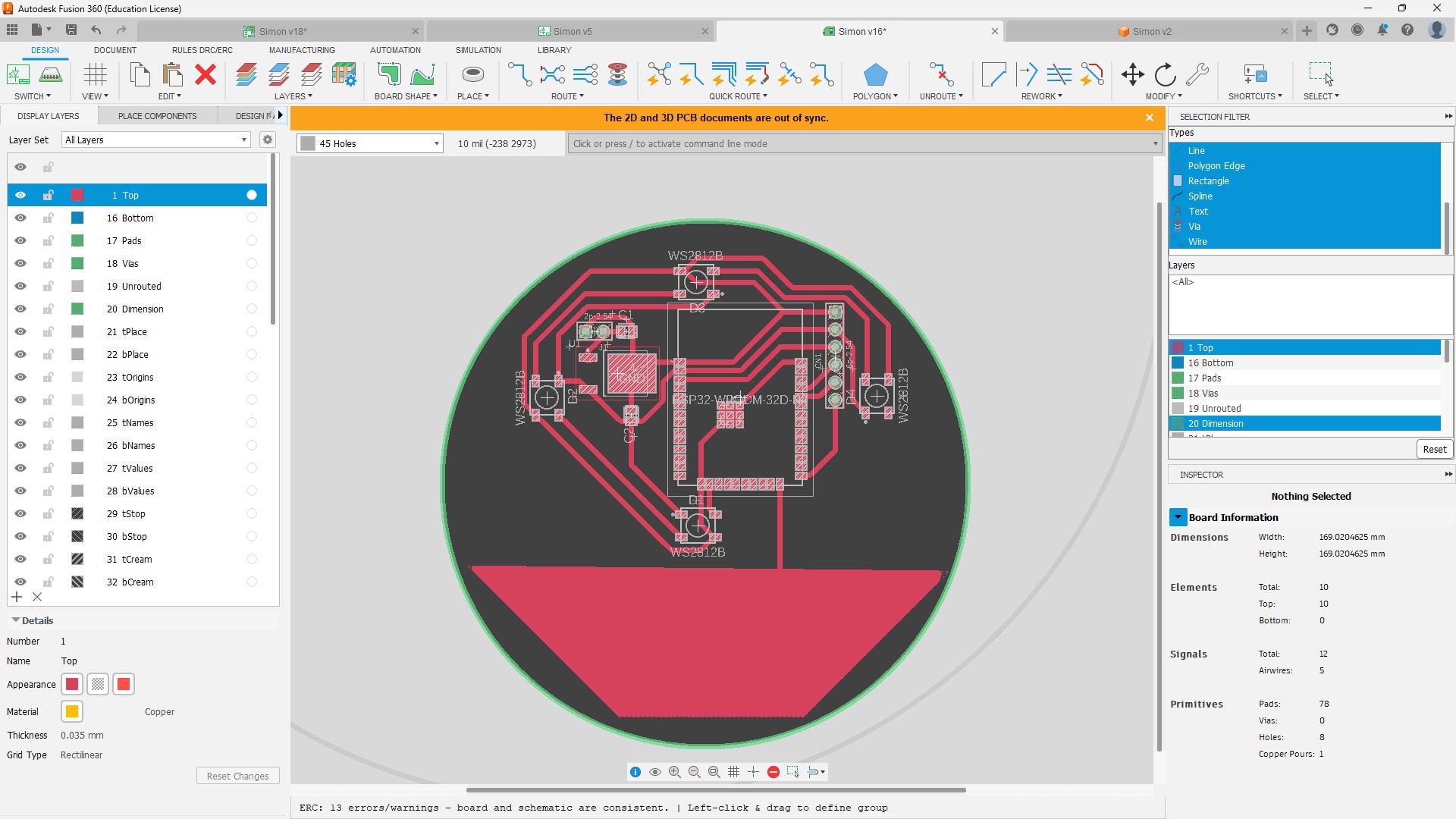
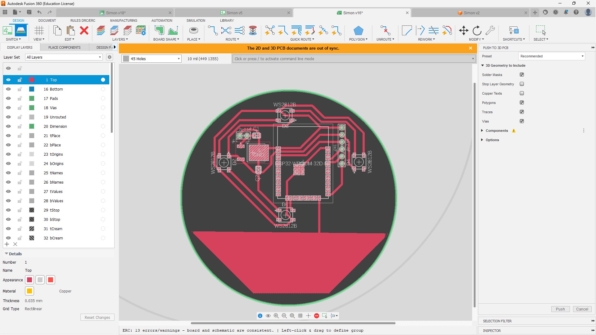
3. Create the PCB layout
The steps I followed to create the PCB layout where:
- Set the position of the objects that I want in a certain place.
- Try to make blocks of electronics that work together (Energy, Power supply, Inputs, Etc.)
- Start routing and playing until you get it right.
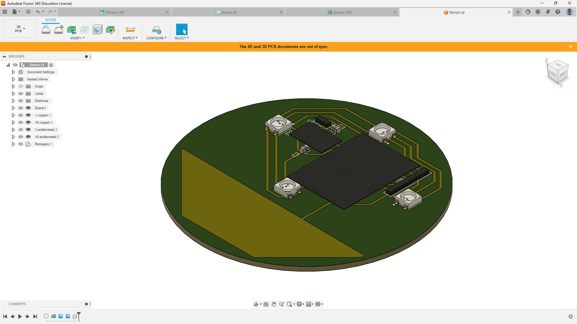
4. Checkout the 3D model
To create a 3D model you just have to click on the button "Push to 3D PCB" located on the top left corner on fusion and enjoy the result
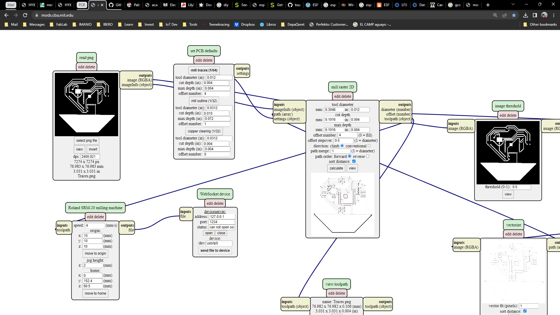
5. Create the GCode
The way to create the GCode is by using mods, and the steps I followed where:
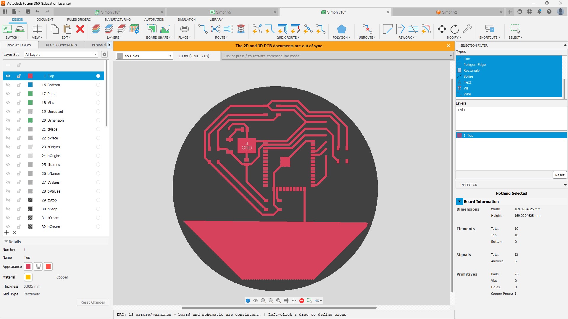
- On the PCB view on fusion set the layers so you can only see the top layer.
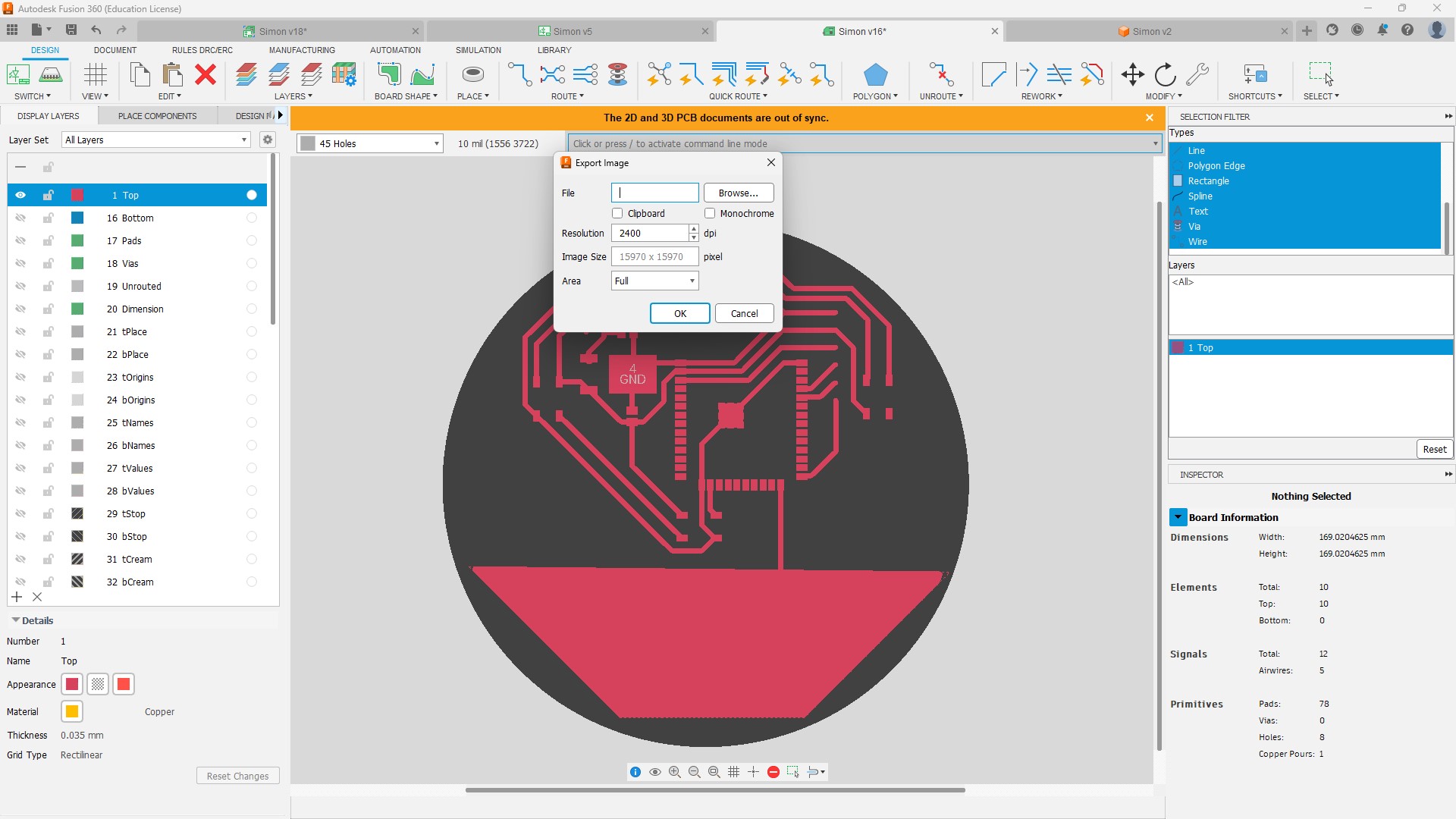
- Then on the command line write export, then select PNG and select monochromatic and set the highest resolution possible.
- Repeat these process for the outline and the holes if there are any.
- Open the page https://mods.cba.mit.edu/
- Right click and select Programs -> Open Server Programs -> Machines -> Rolland -> Mill -> SRM-20 -> PCB png
- Load your .png image and select is you want to mill traces or the outline depending on your image.
- Click on calculate and the file containing the GCode will be automatically downloaded to your computer.
6. Mill your PCB
To mill the PCB you have to have installed the Candela program, then follow this steps:
- Click on file and select open.
- Select the file you want to mill.
- Verify that everything looks well on the layout. (If you want you can watch how the pcb will be milled by selecting the "Check mode" on the bottom left corner of the program)
- Set the origin of the piece to fit your board on the milling machine.
- Hit Send.
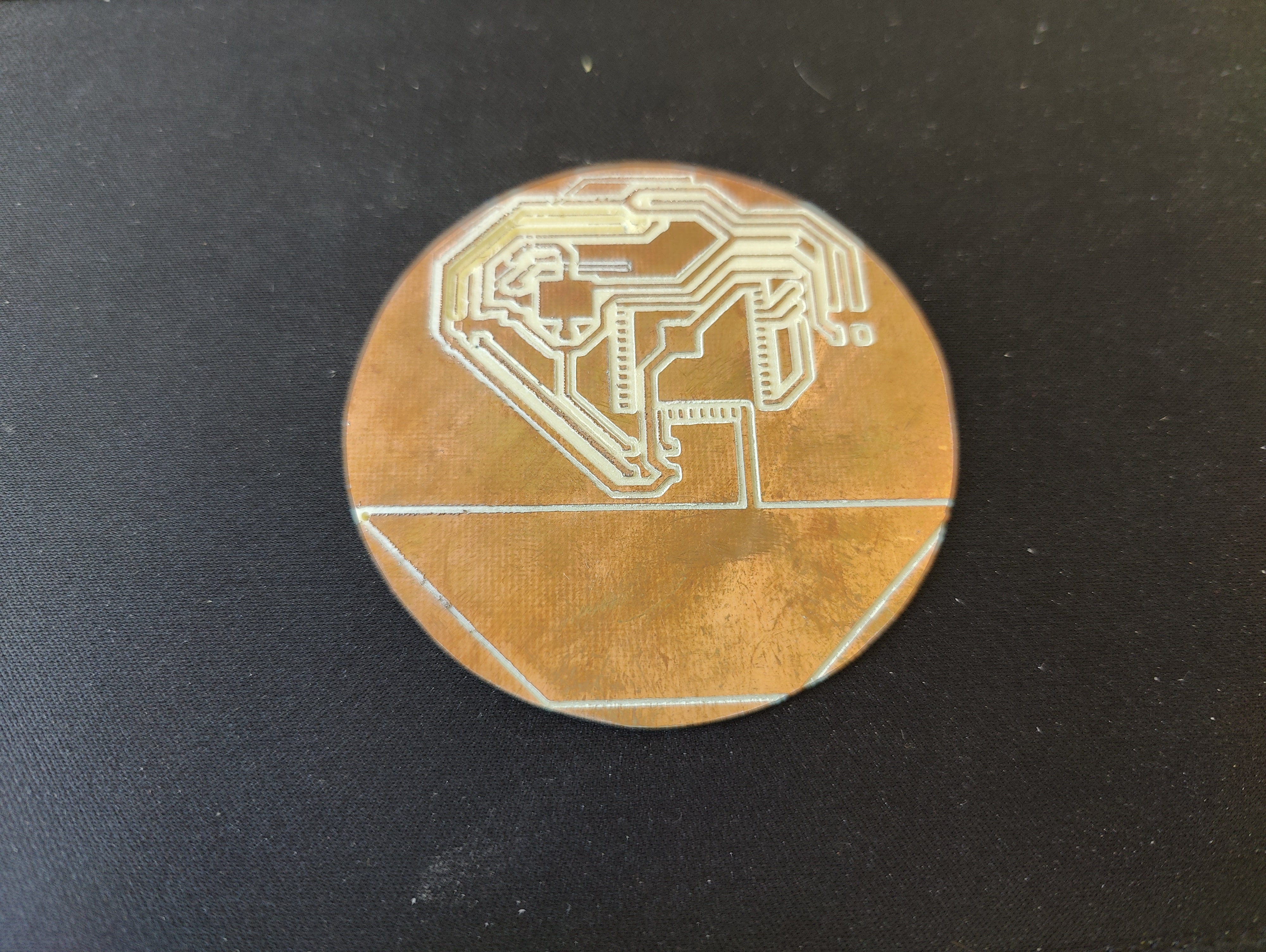
Test mill on MDF.
Milling the PCB
The milling machine stops and I don't know yet the reason.
7. Solder your circuit
To solder the circuit is better to start from the center out and from the smallest components to the largest.
8. Final result
Finally I made it work changing the g-code program that I used to send the signal to the controller
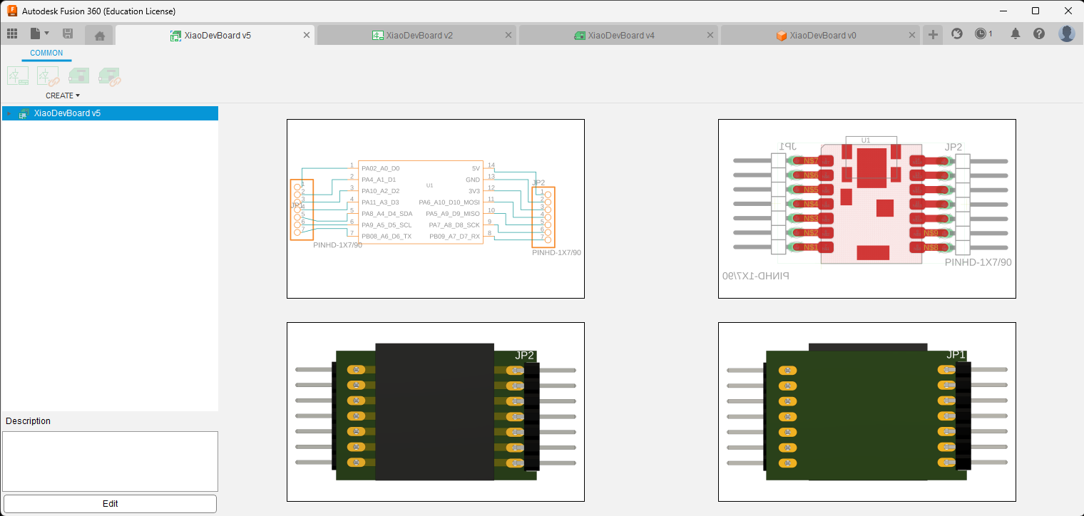
I did managed to make the board, but I changed the circuit and decided to make a generic pinout board so it would help me develop the next projects.