For this week I learned how to obtain the Kerf and how to characterize a material in a laser cutter using a power vs. speed test, then I designed an assembly kit bases only on joints that do not require any glue.
Using the Laser cutter
1. Characterizing the laser cutter
I used the information that my lab already had to cut my material to adjust the correct power and velocity for the material. I will characterize a new material in the future to also do this process myself.
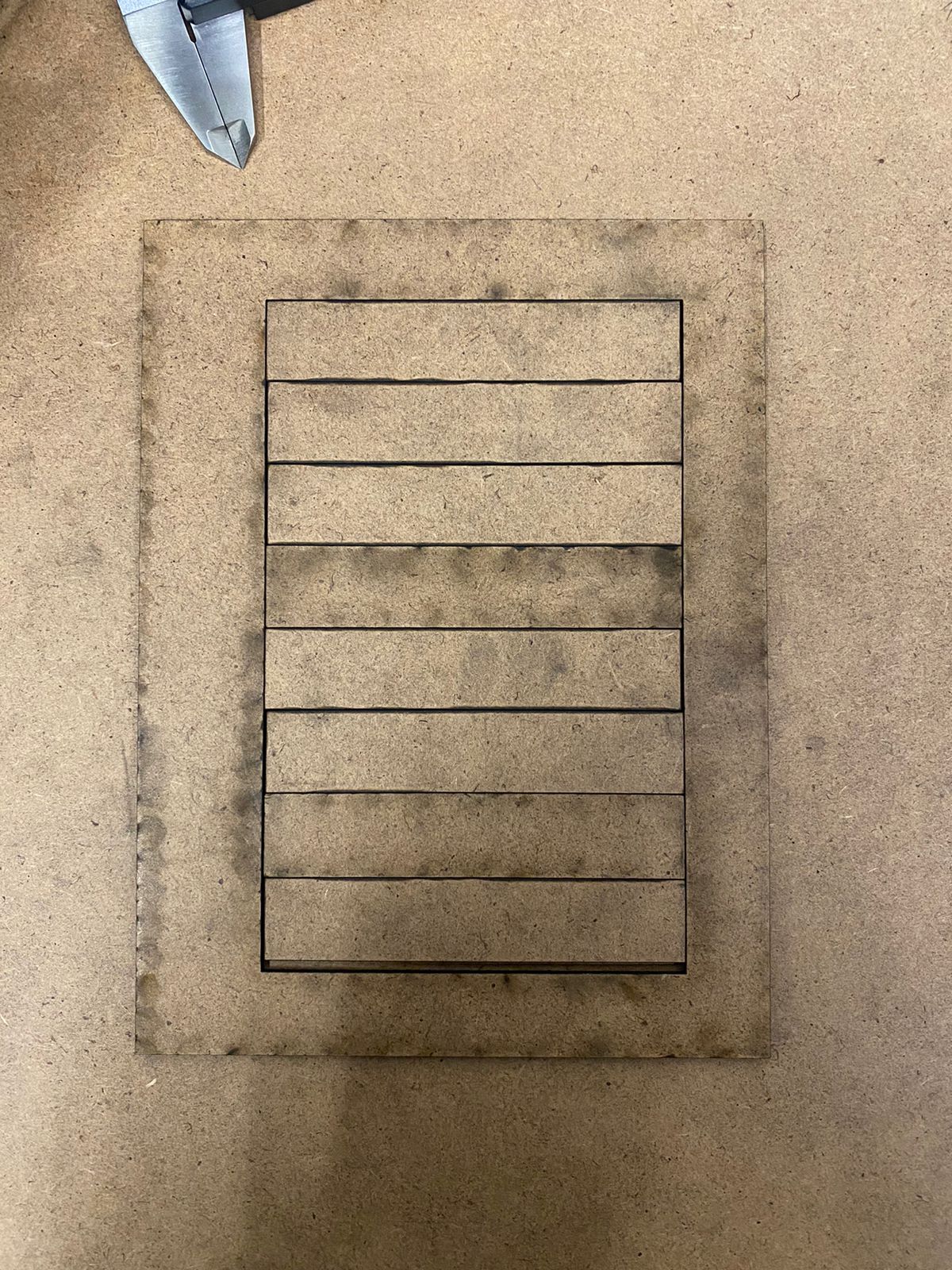
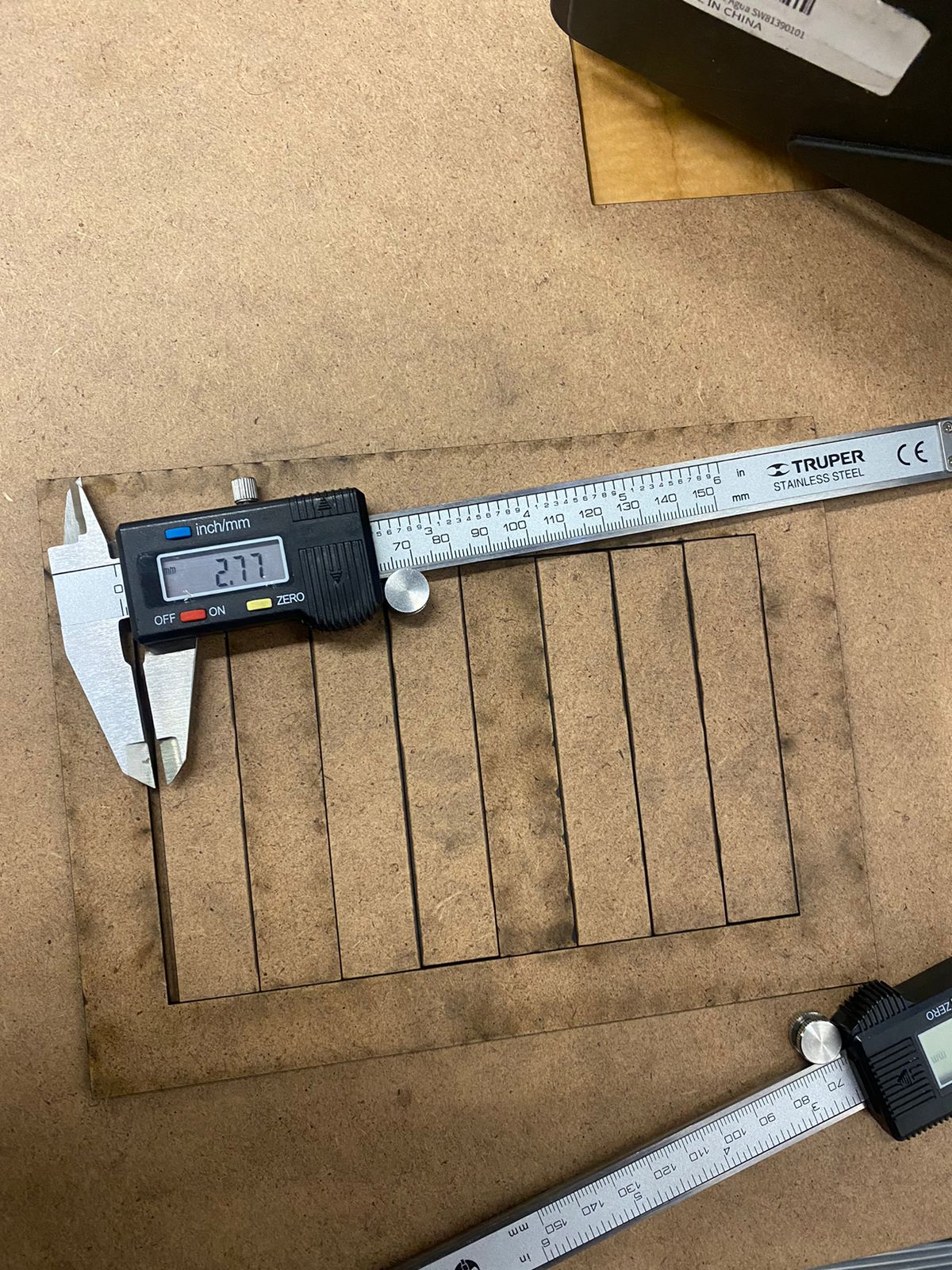
2. Obtaining the kerf
The first step was to design a CAD model based on rectangles to sum multiples of the kerf to then obtain that measure and divide it by the number of lines.
Kerf=dx/lines
Assembly Kit
1. Design
2. Cutting
3. Assembling
4. Final product