Computer Aided Design

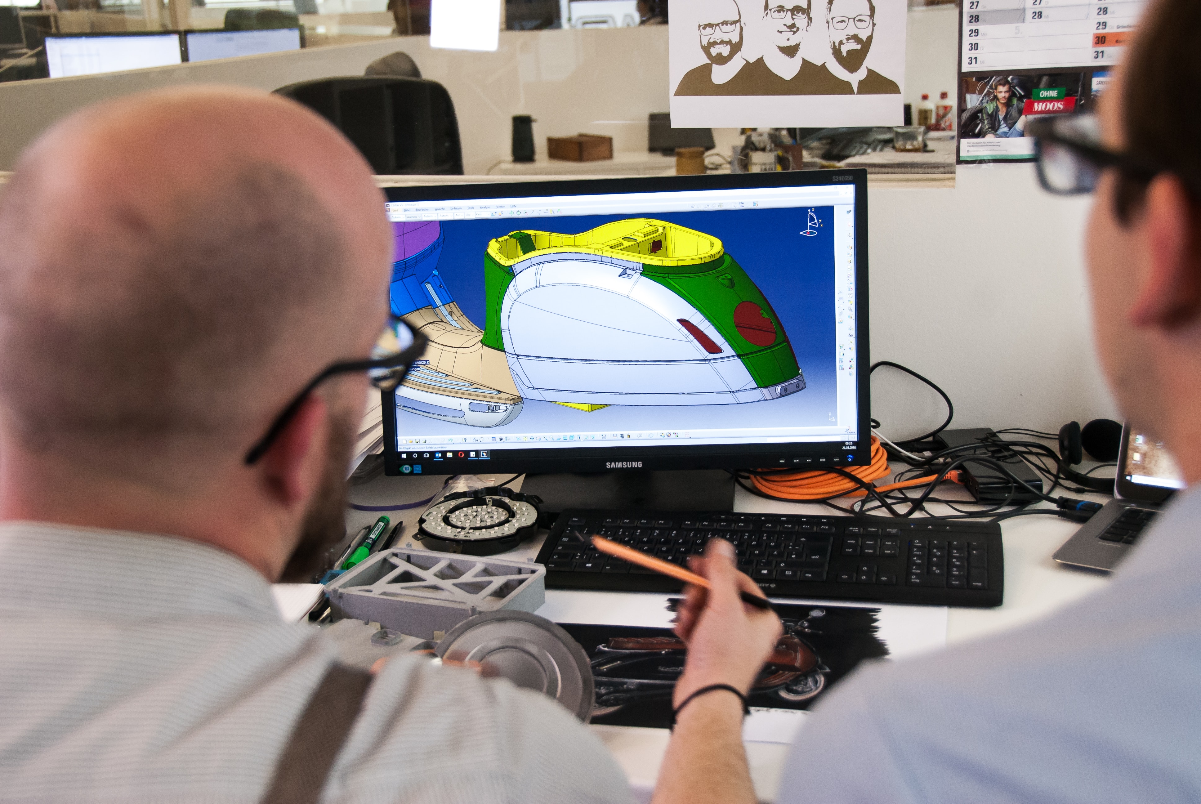
Computer Aided Design (CAD) software can be used to create a wide range of designs, including mechanical parts and assemblies, buildings and architectural designs, electrical and electronic systems, and 3D models for animation and visualization. The software typically includes a variety of tools for creating and manipulating geometric shapes, as well as features for adding annotations, dimensions, and other details to designs.

Overall, CAD has revolutionized the design process, enabling designers to create and test designs more efficiently and accurately than ever before. With the help of CAD software, designers can bring their ideas to life, optimize designs for performance and efficiency, and create products and structures that meet the needs of their clients and customers.

Assignment

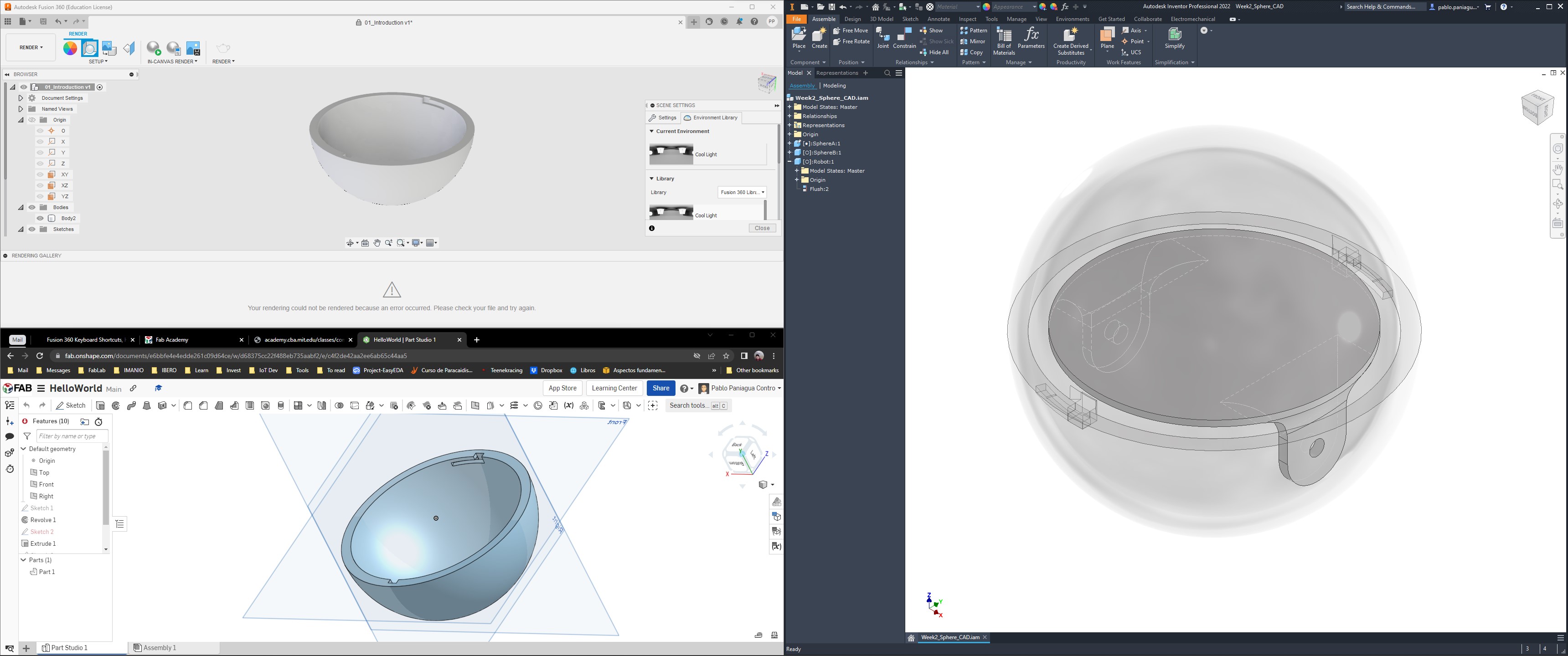
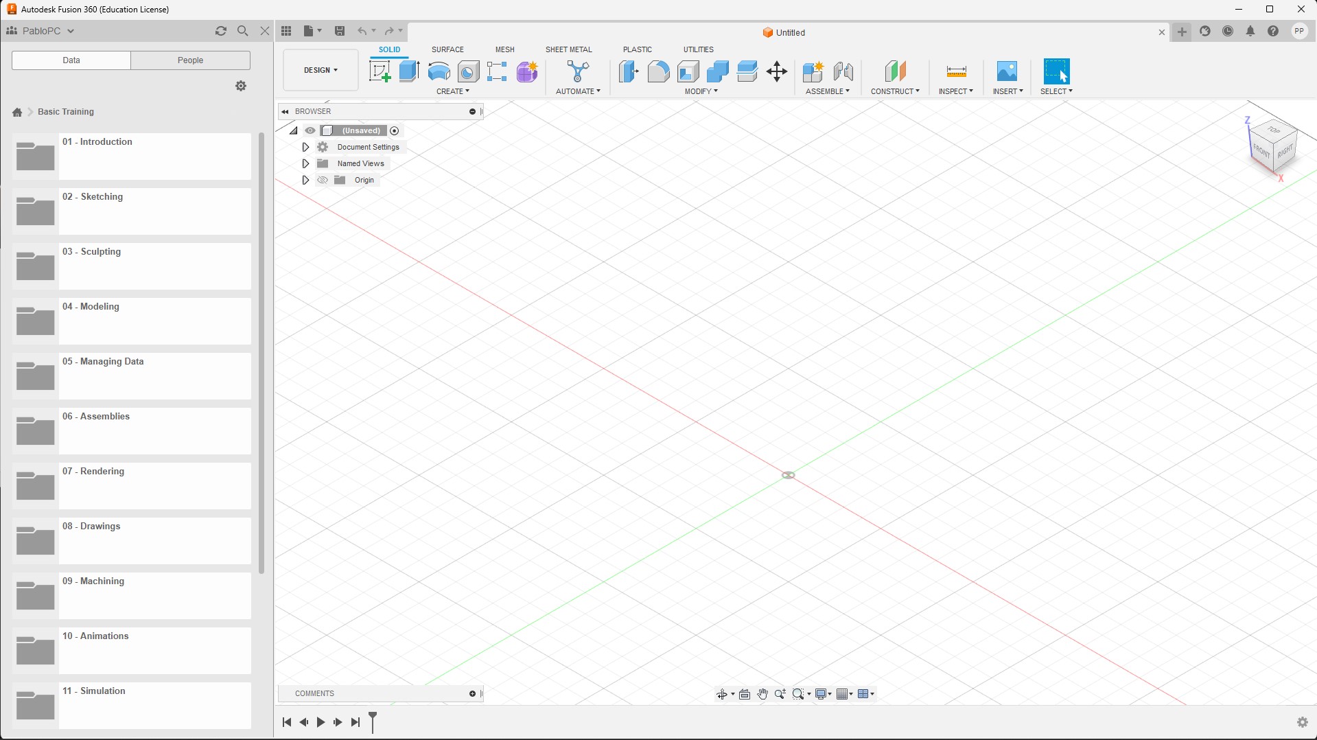
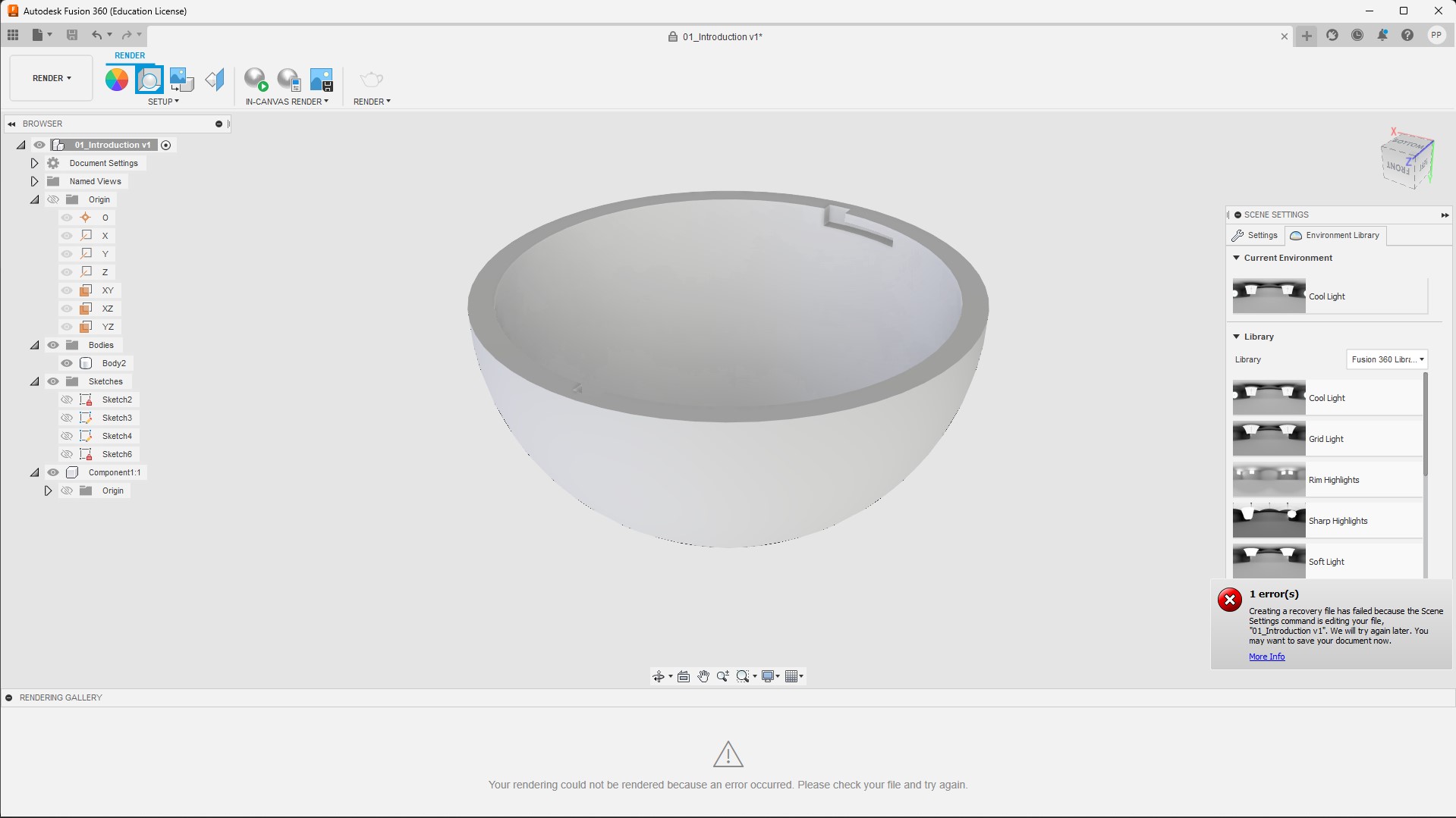
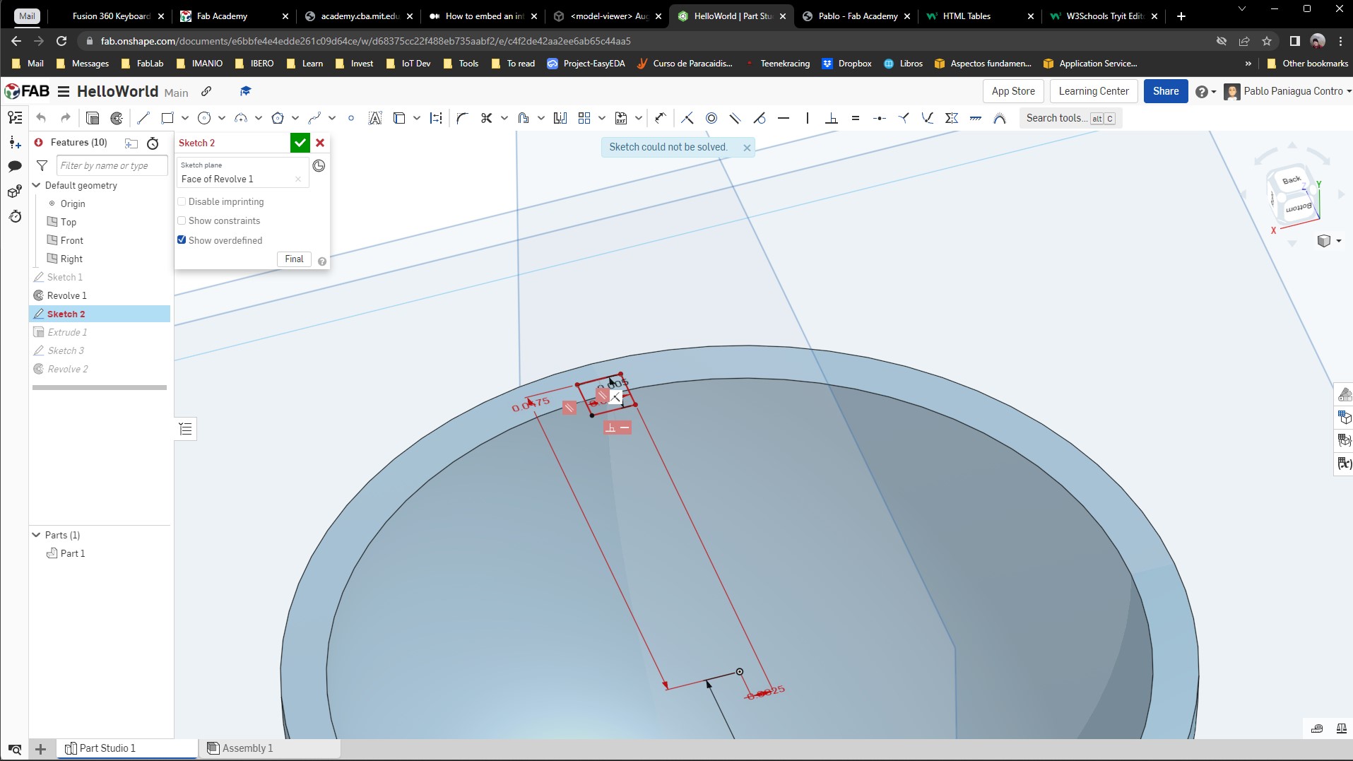
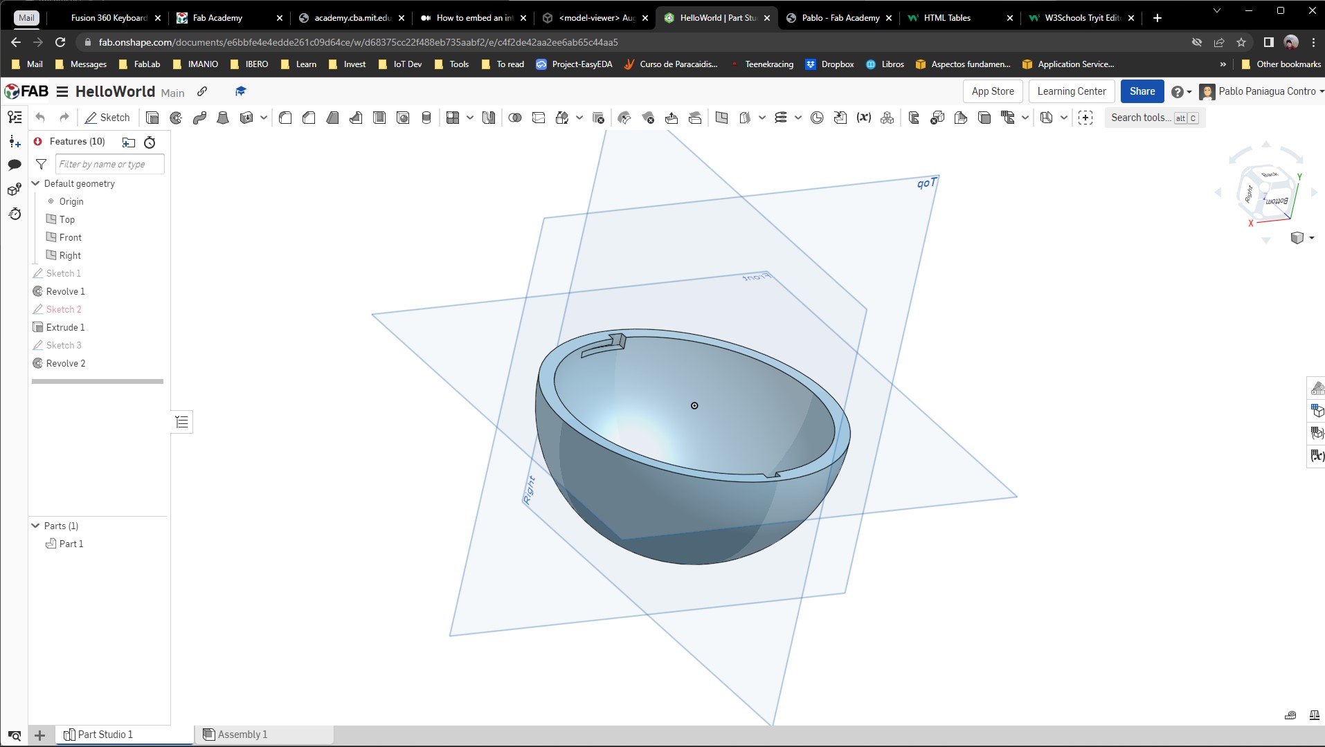
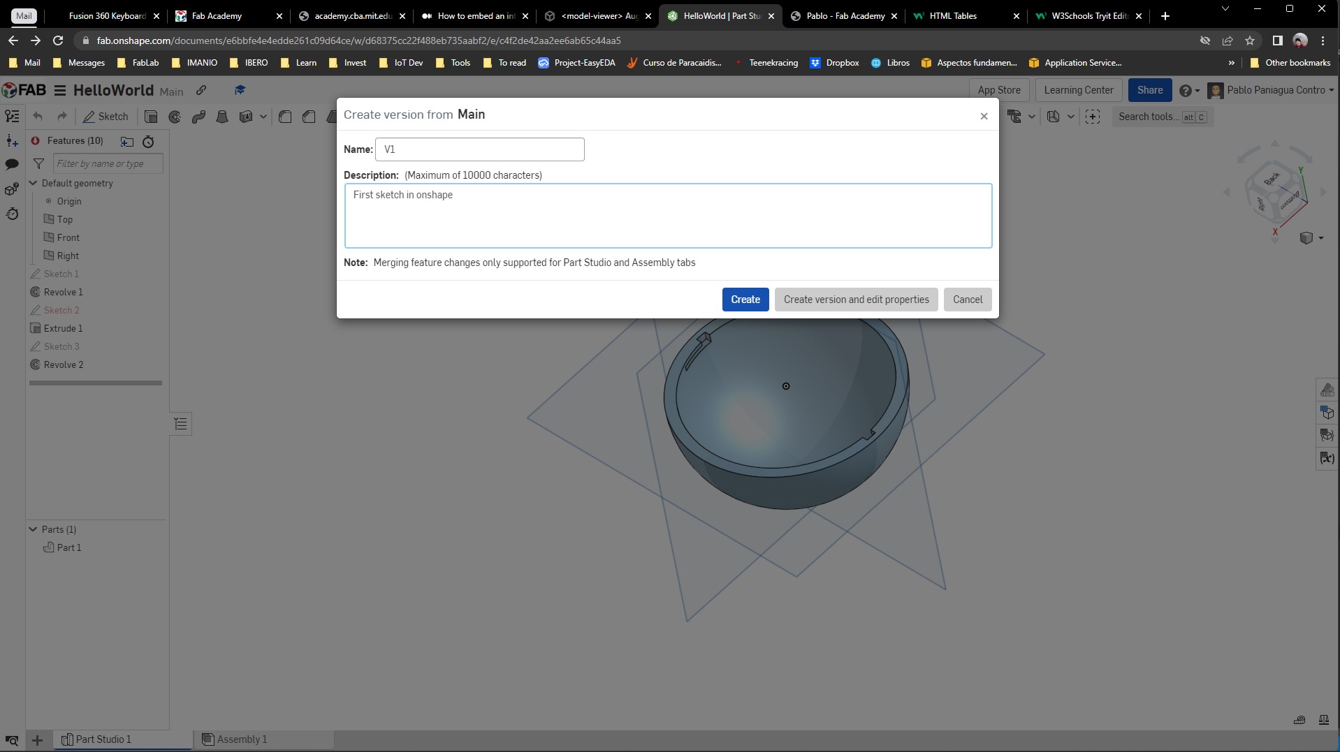
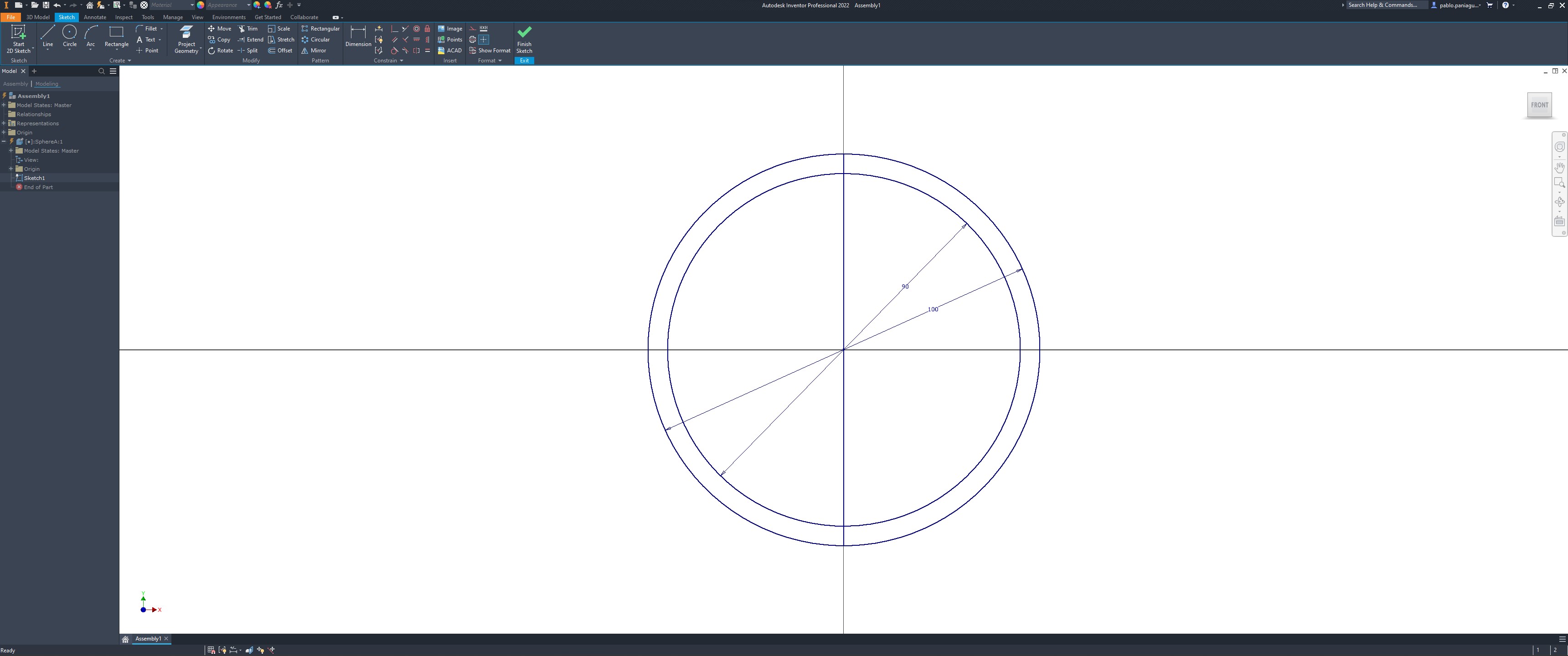
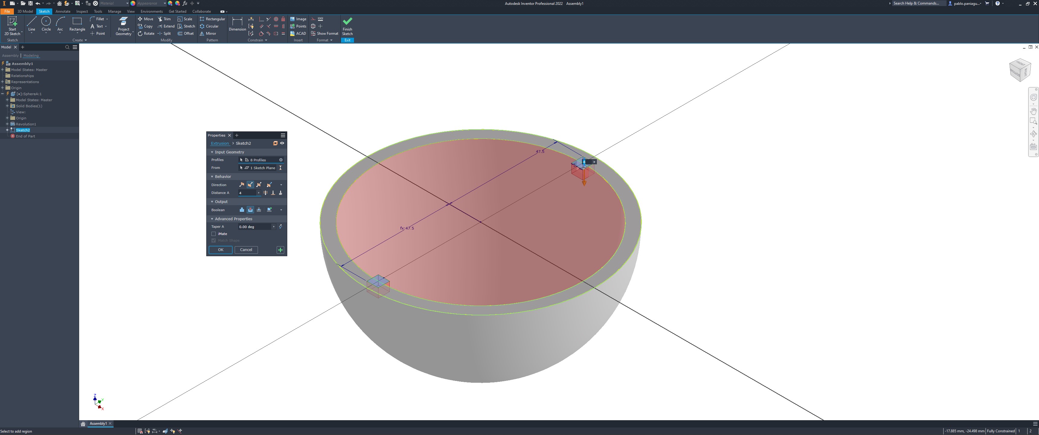
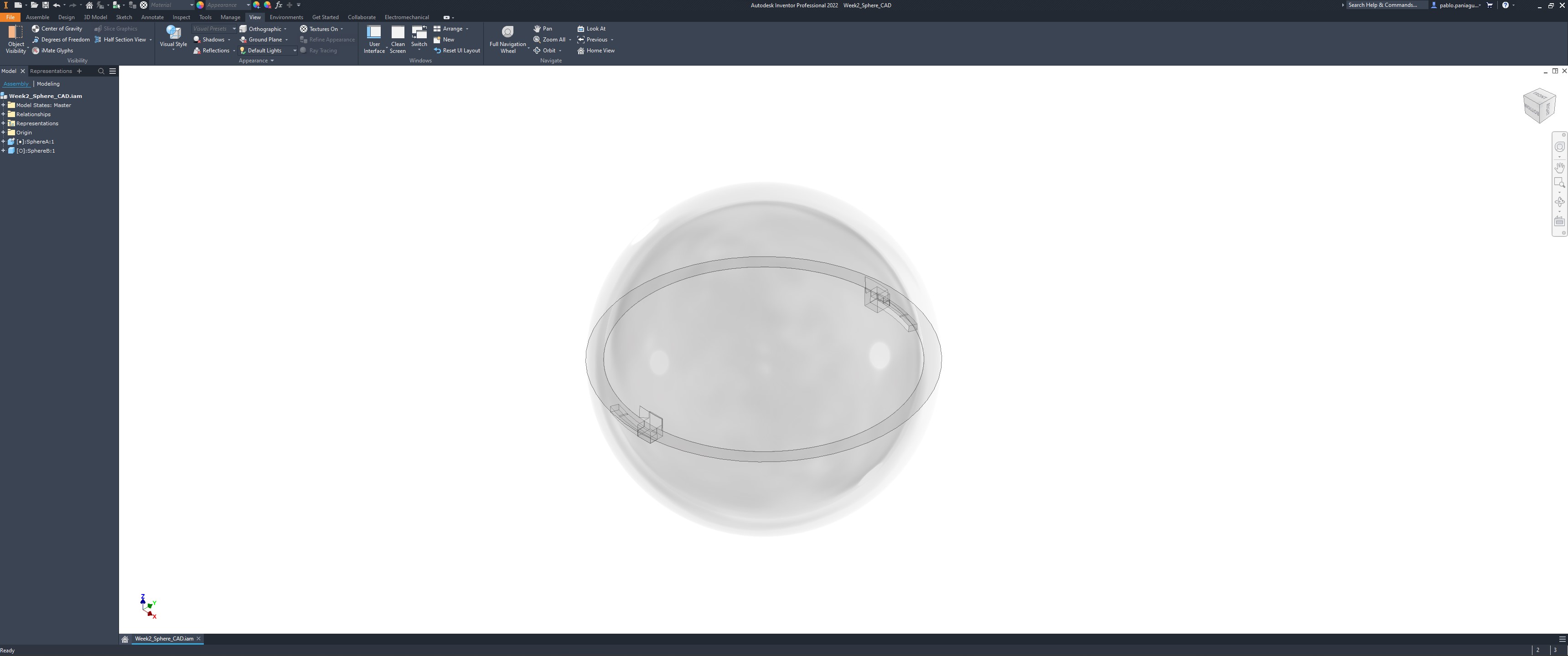
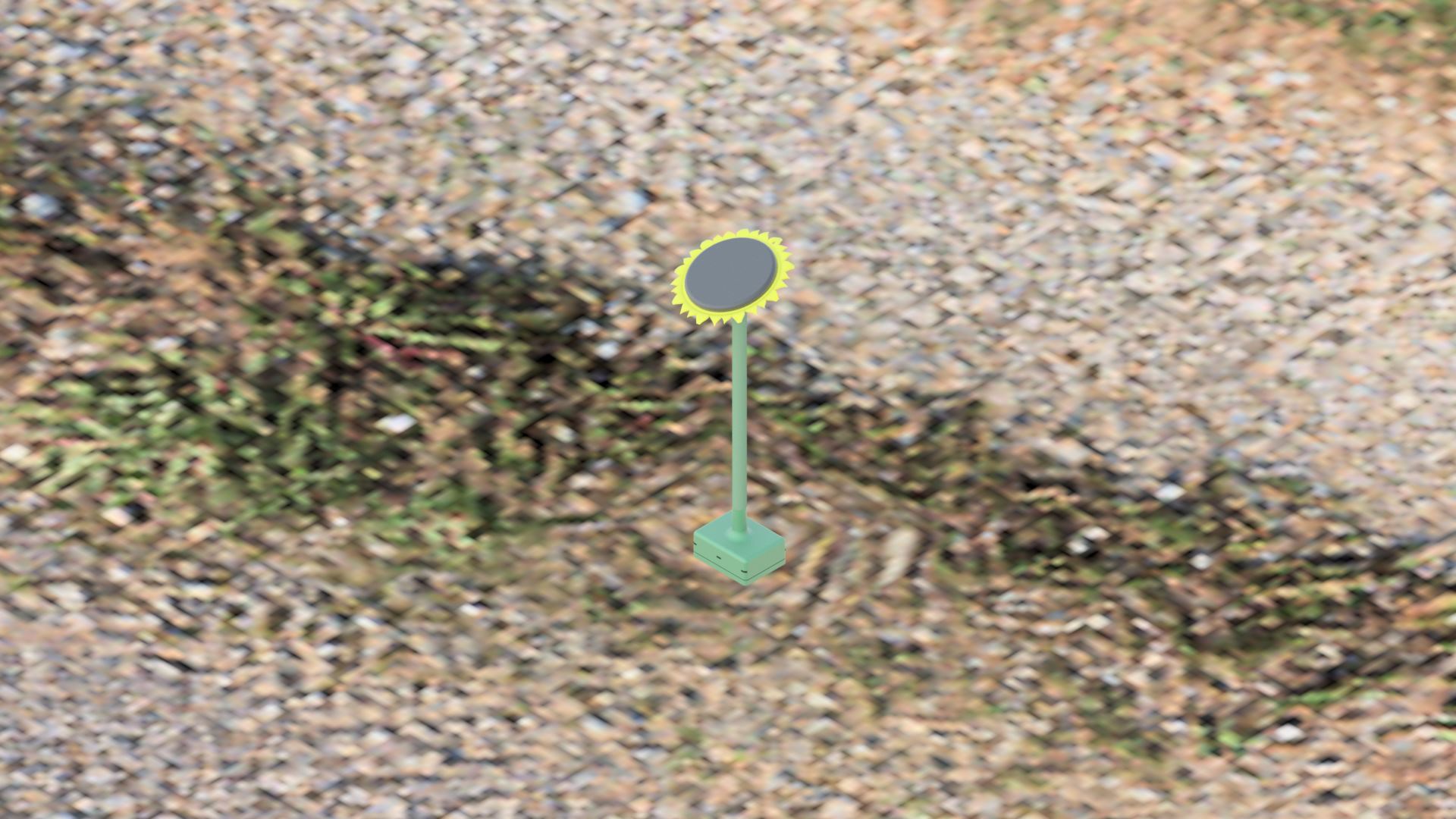
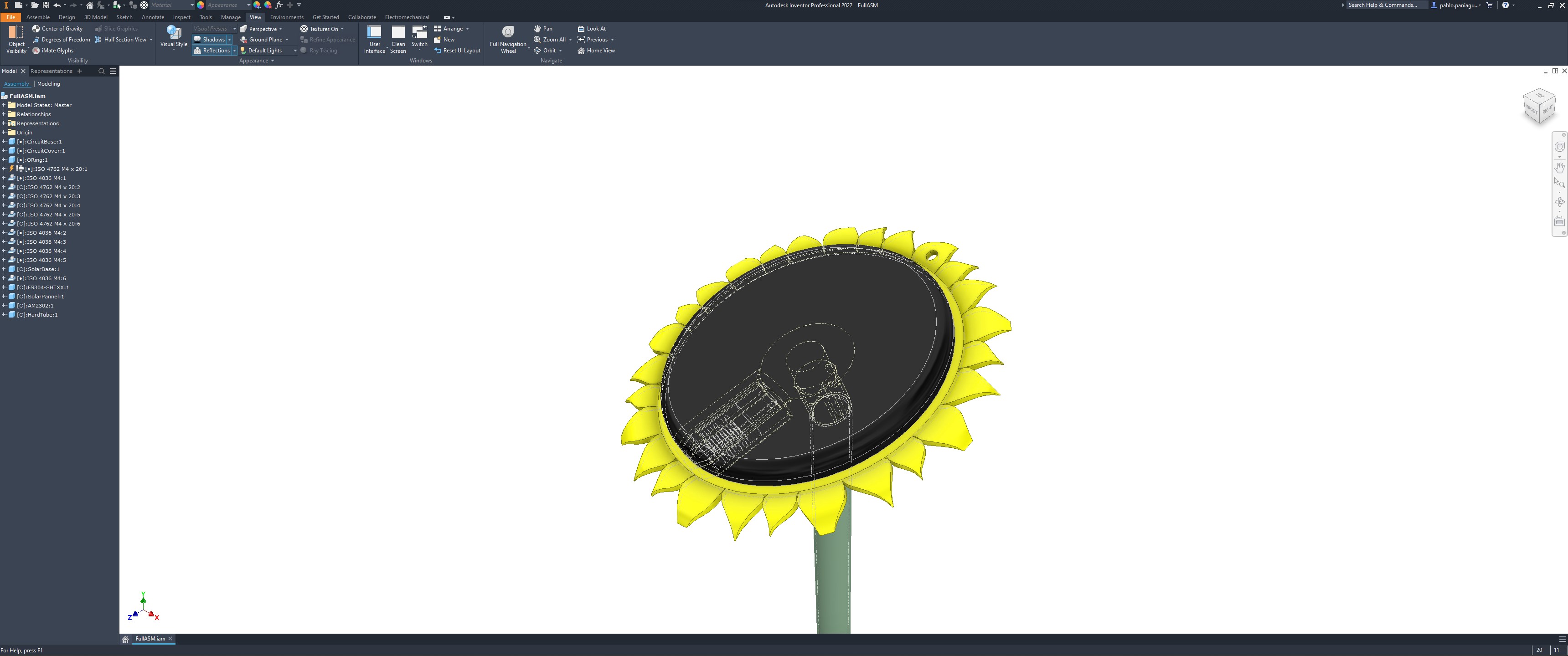
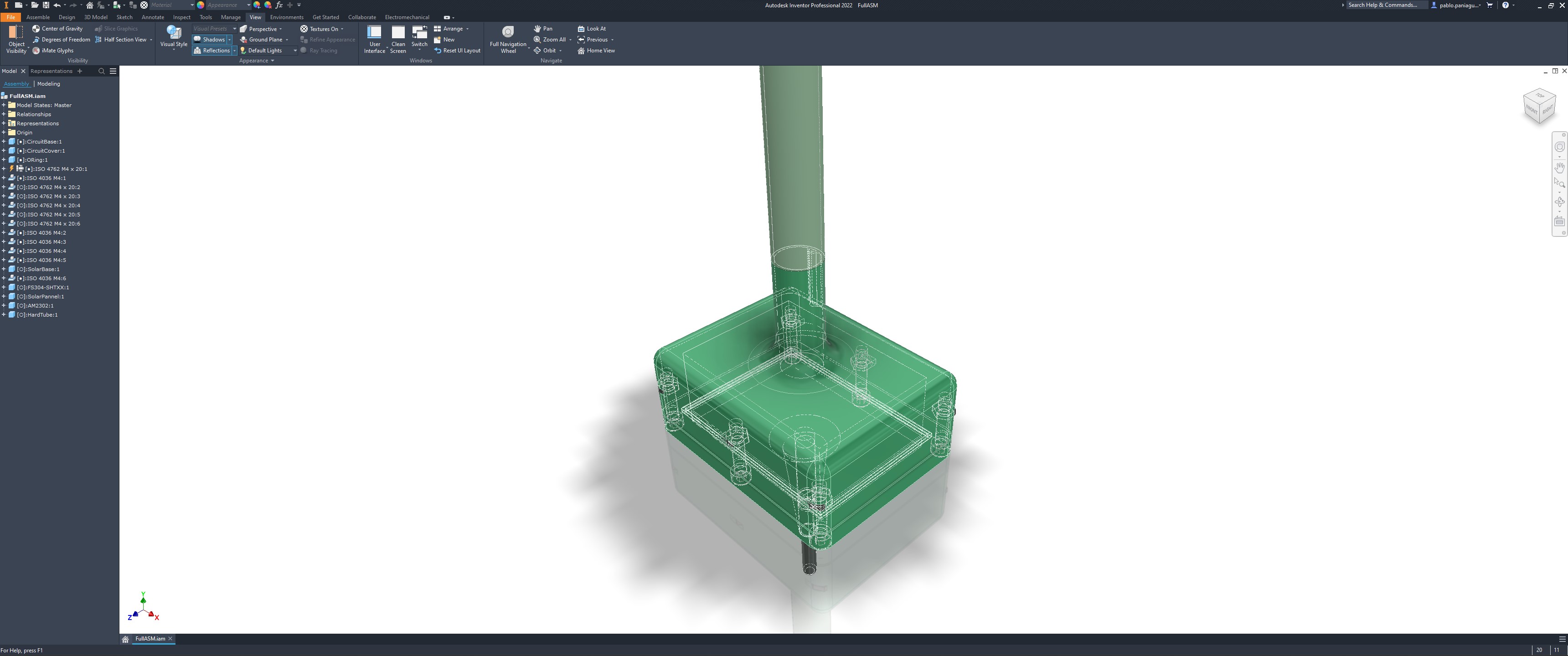
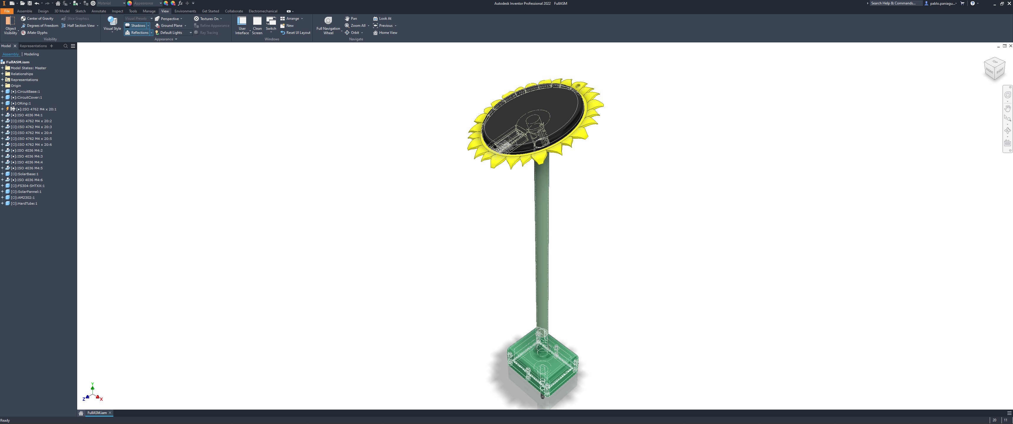
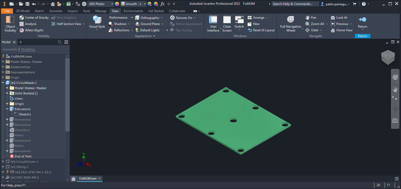
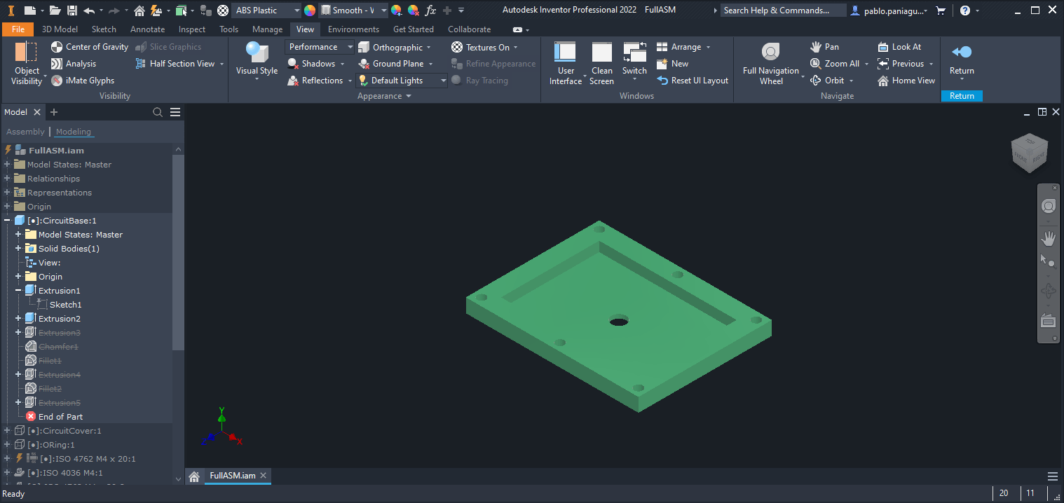
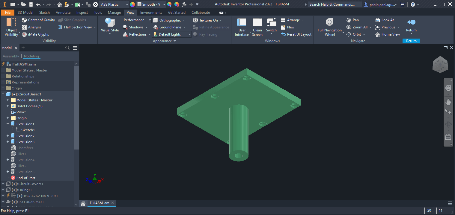
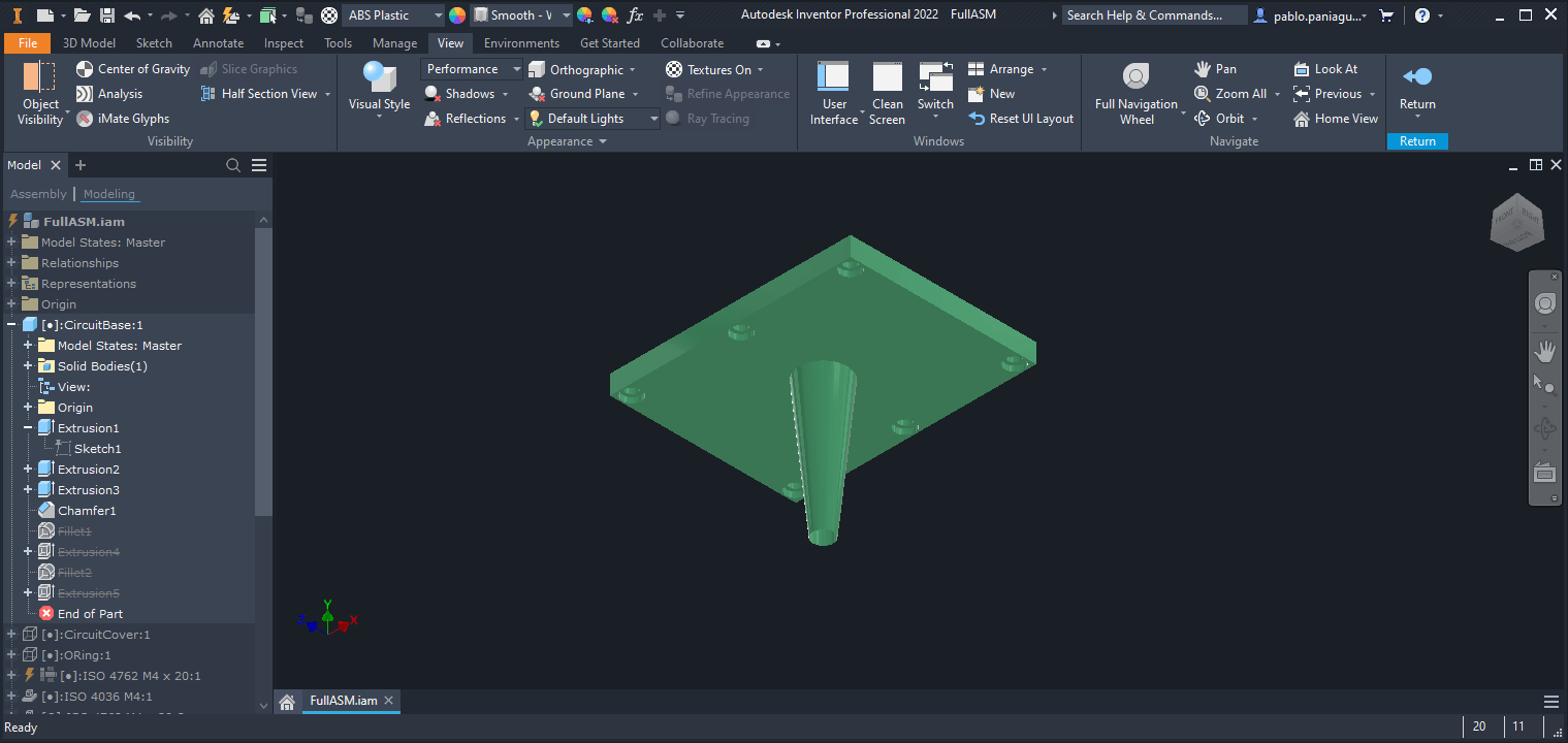
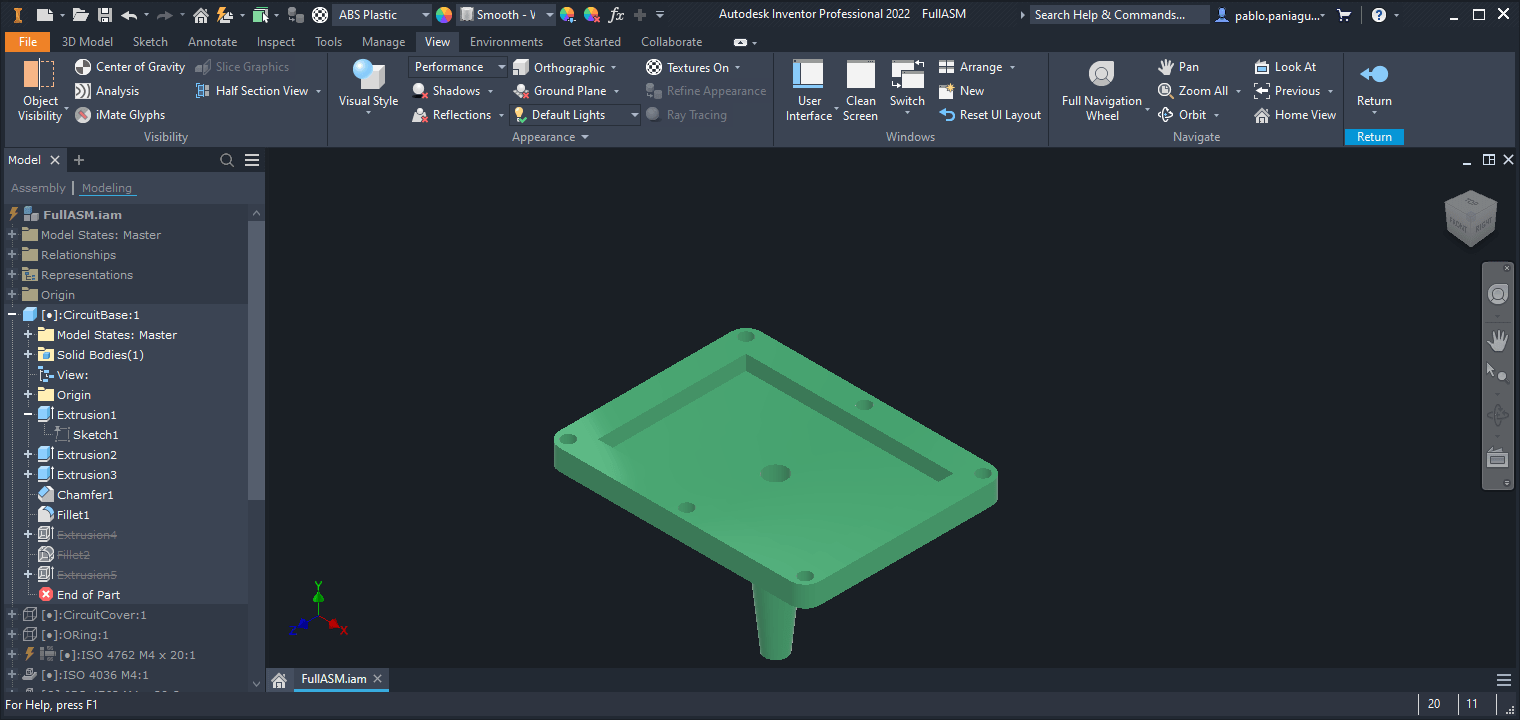
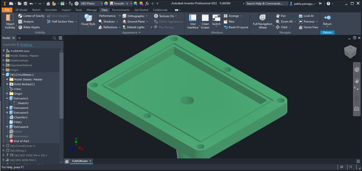
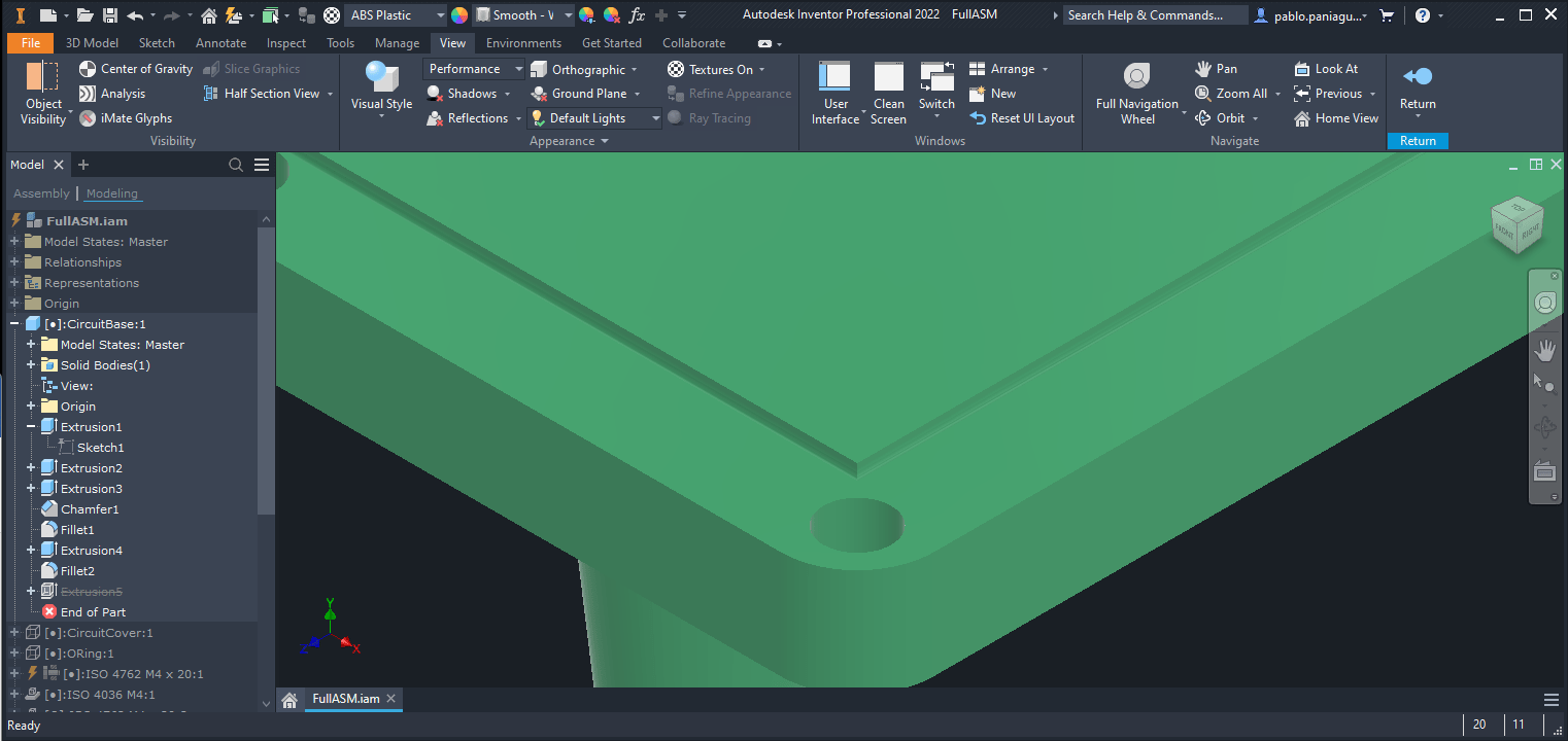
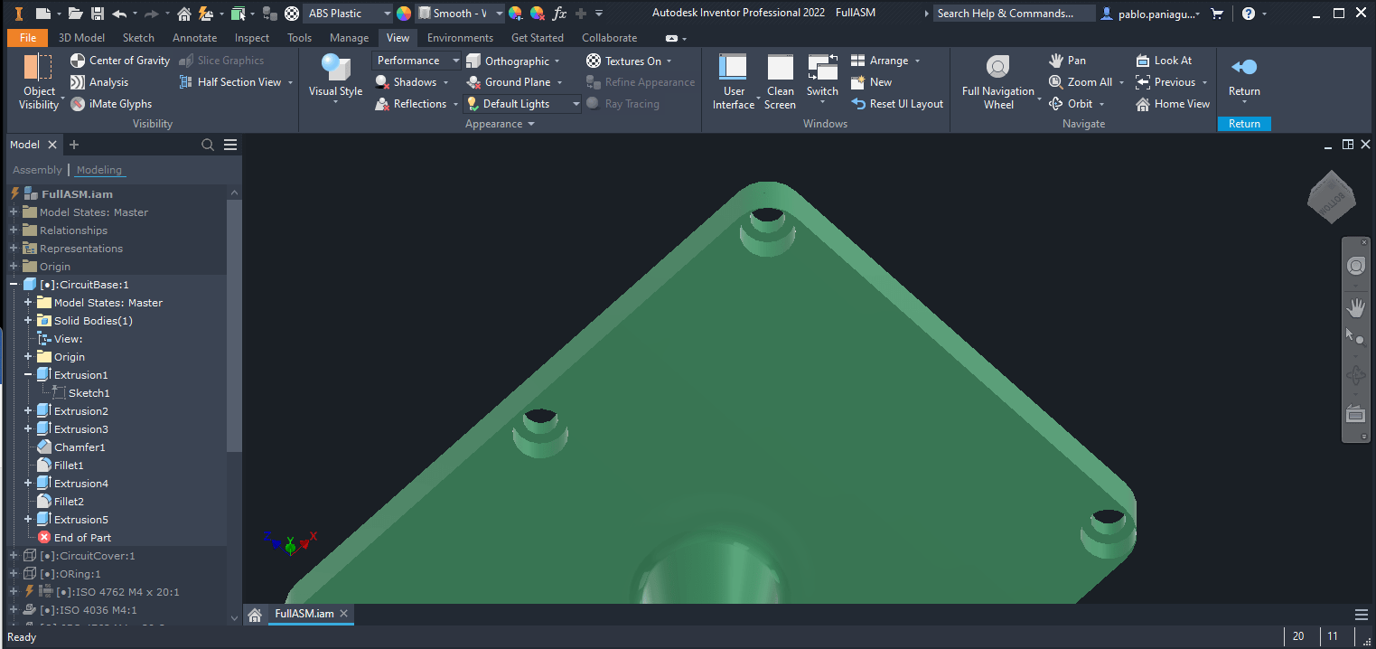
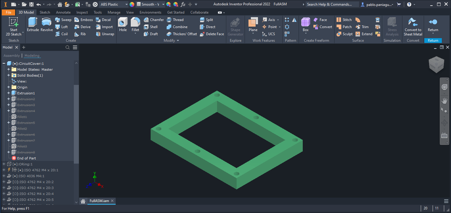
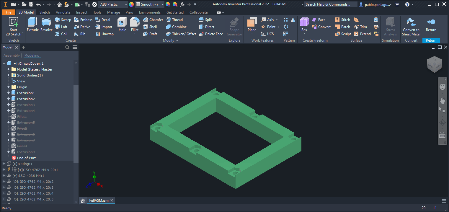
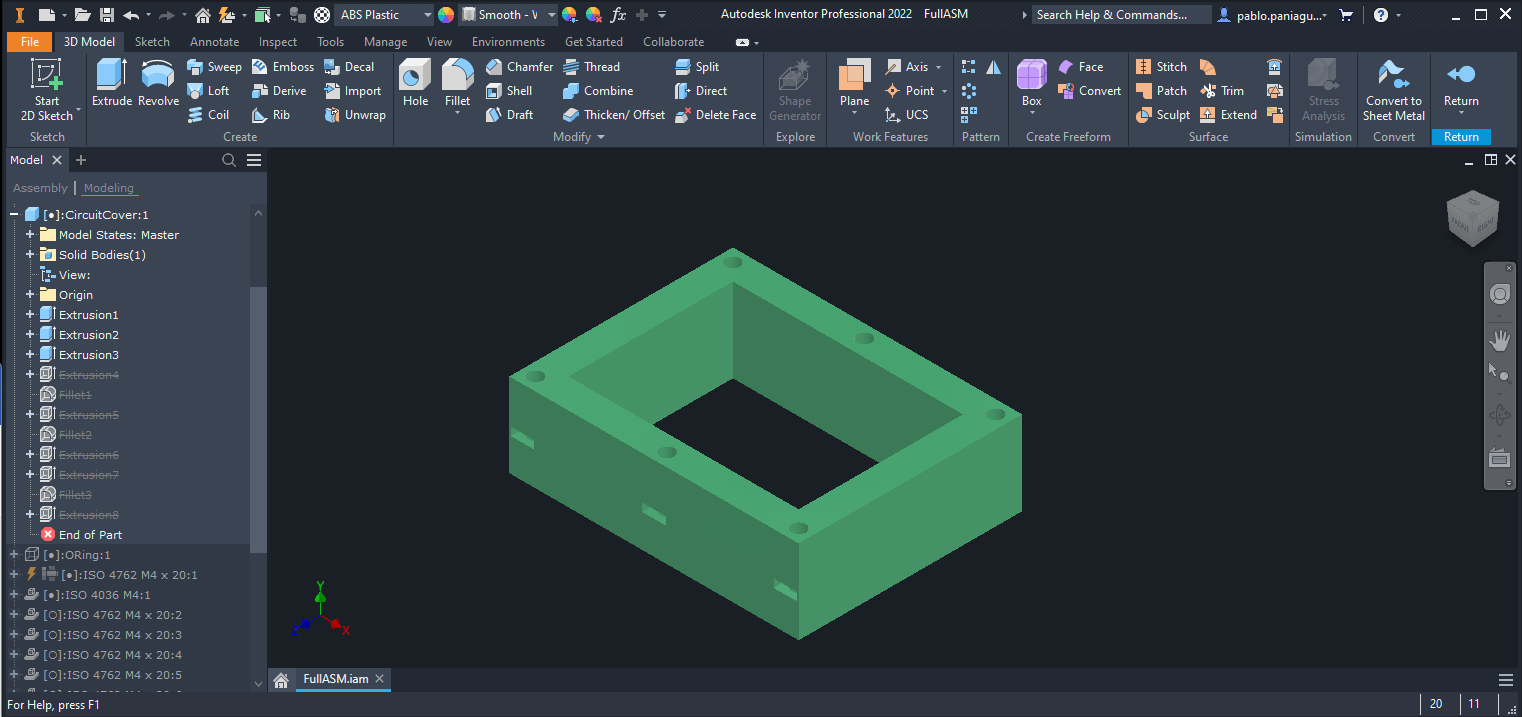
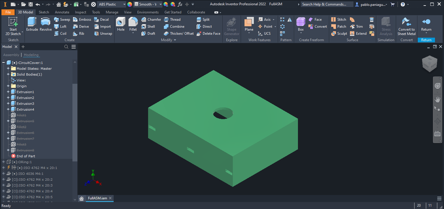
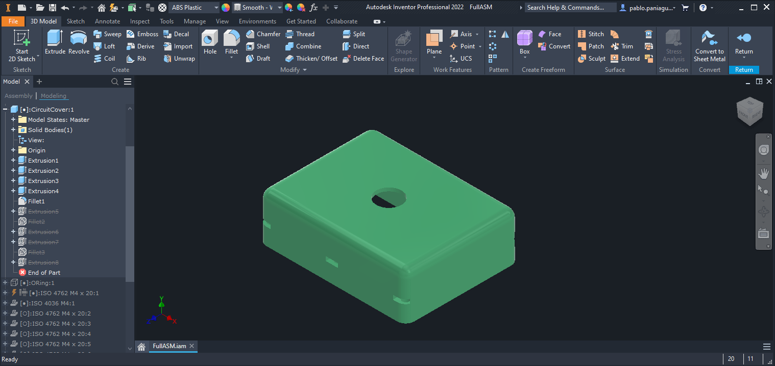
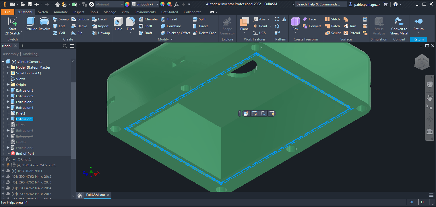
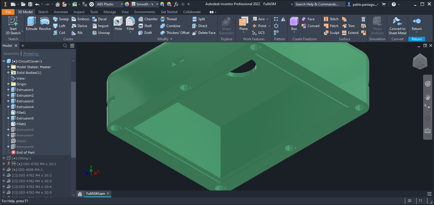
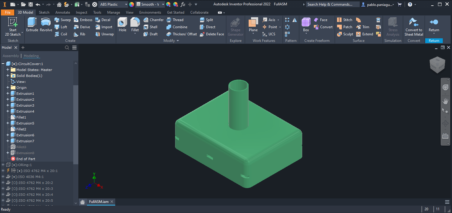
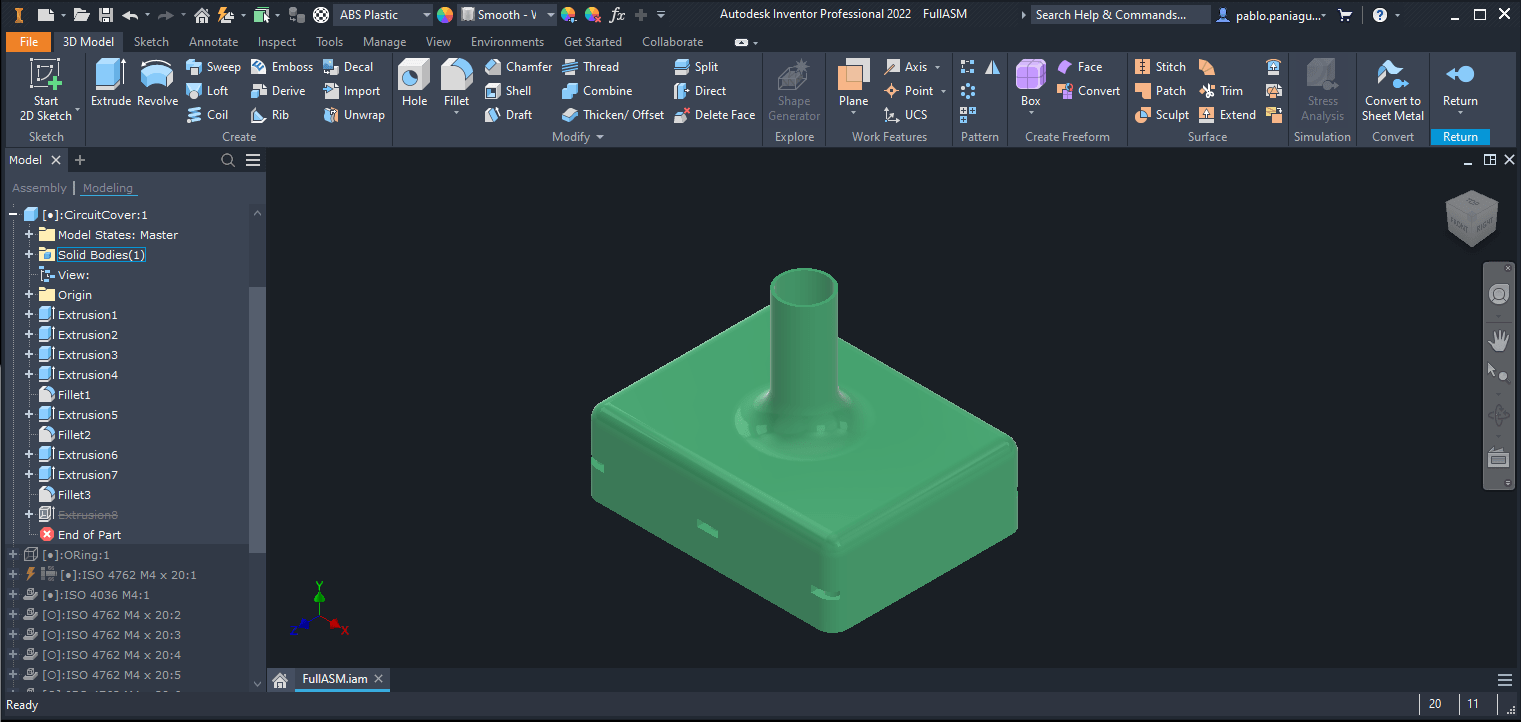
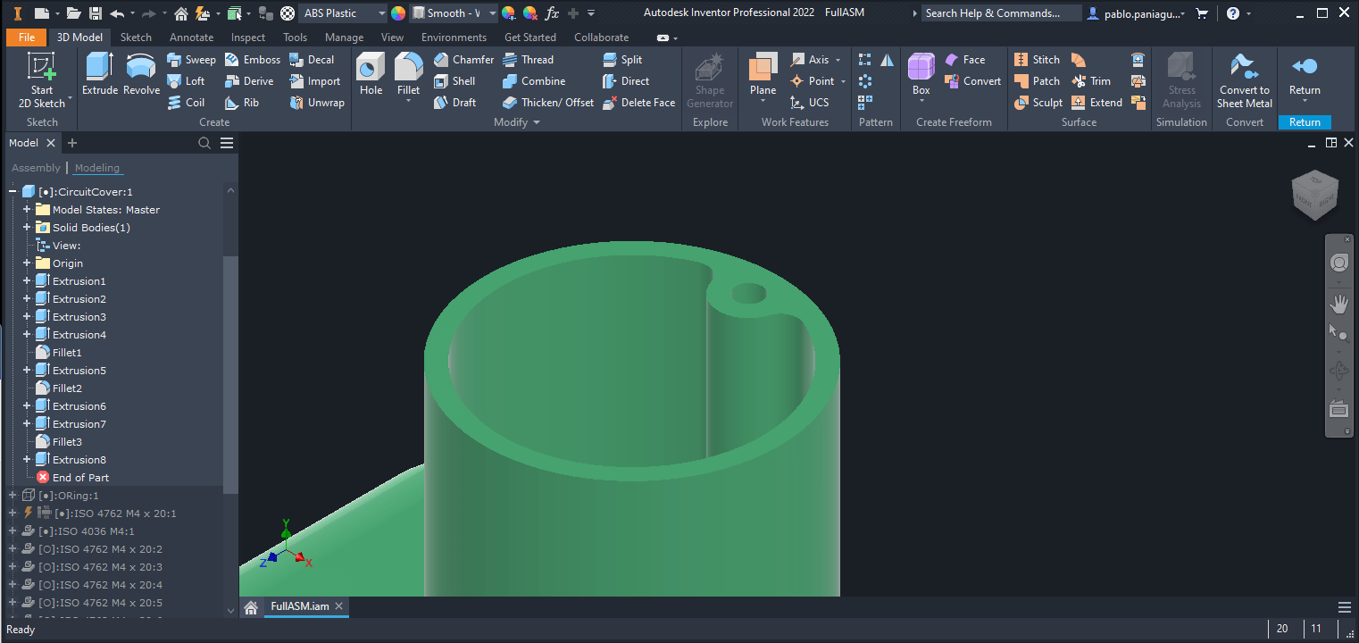
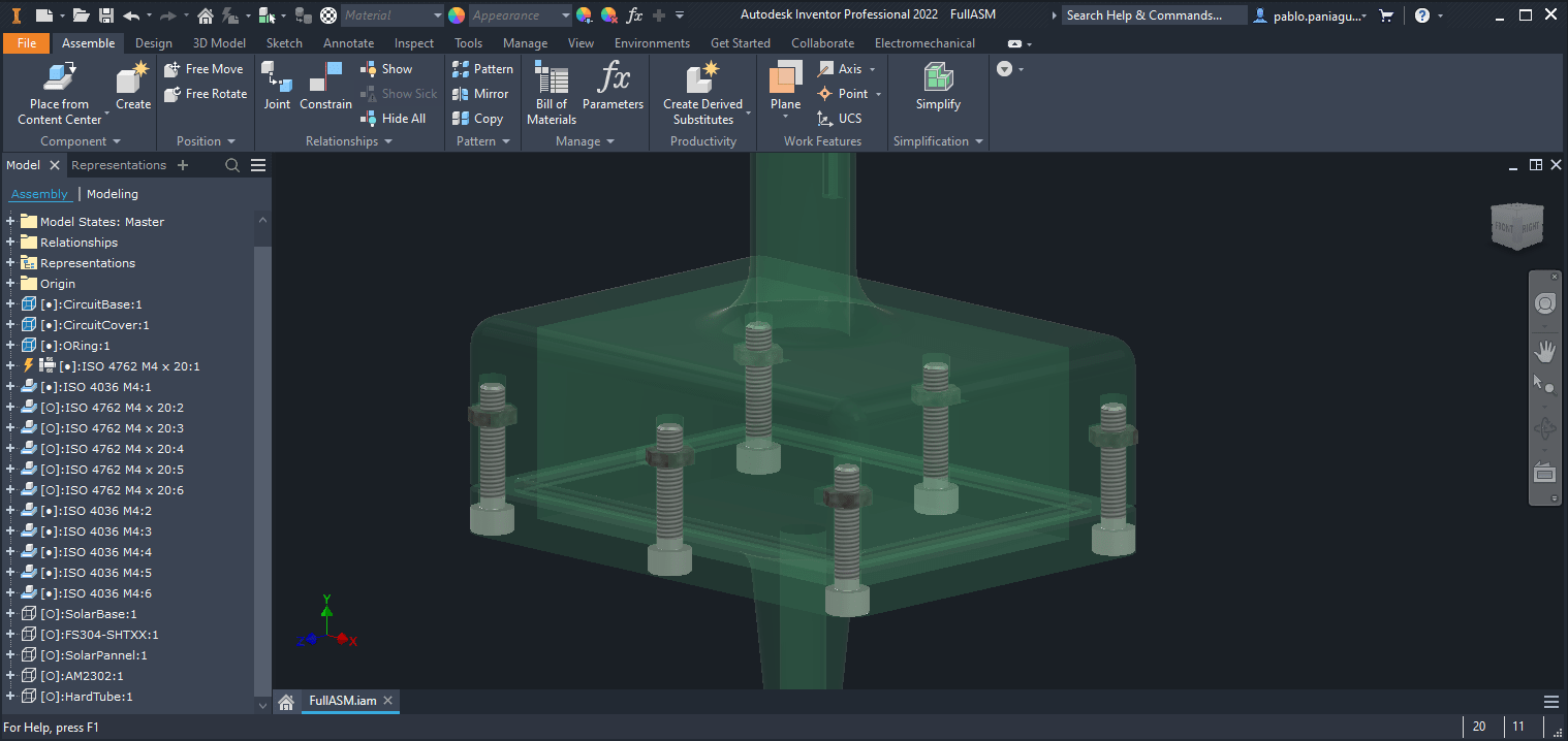
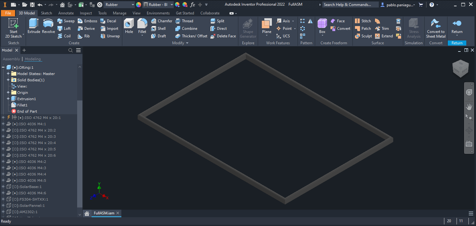
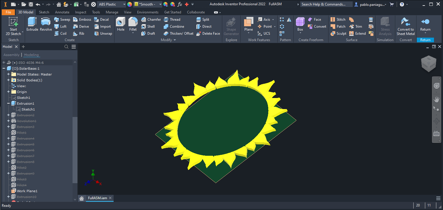
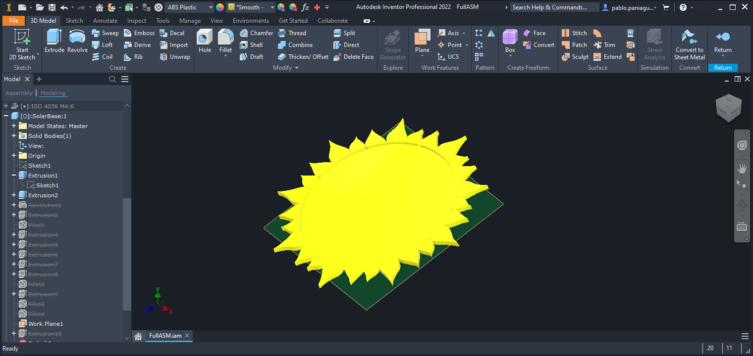
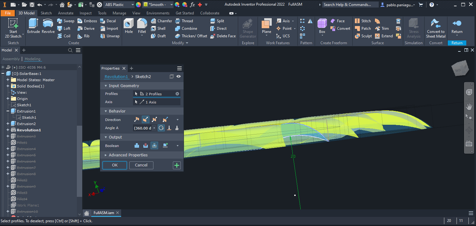
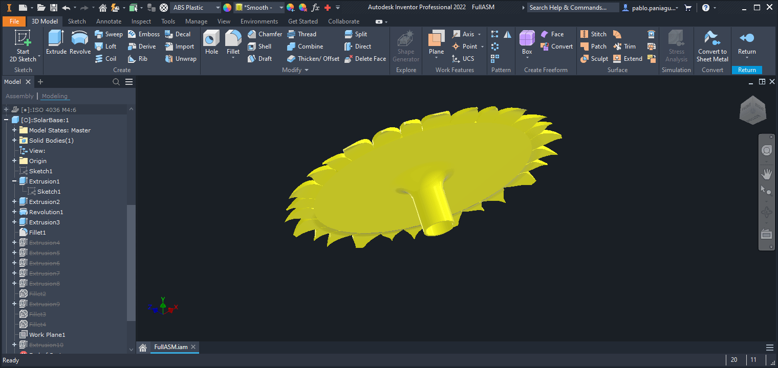
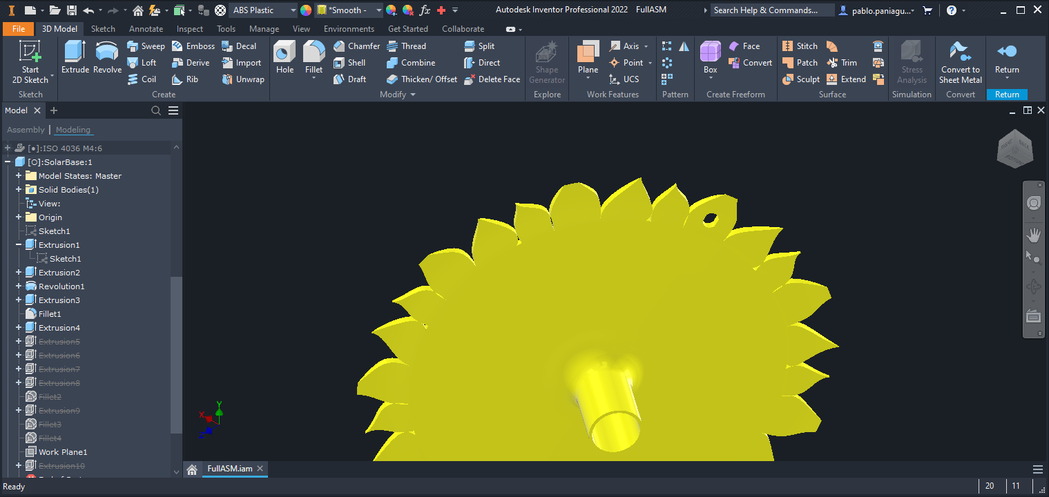
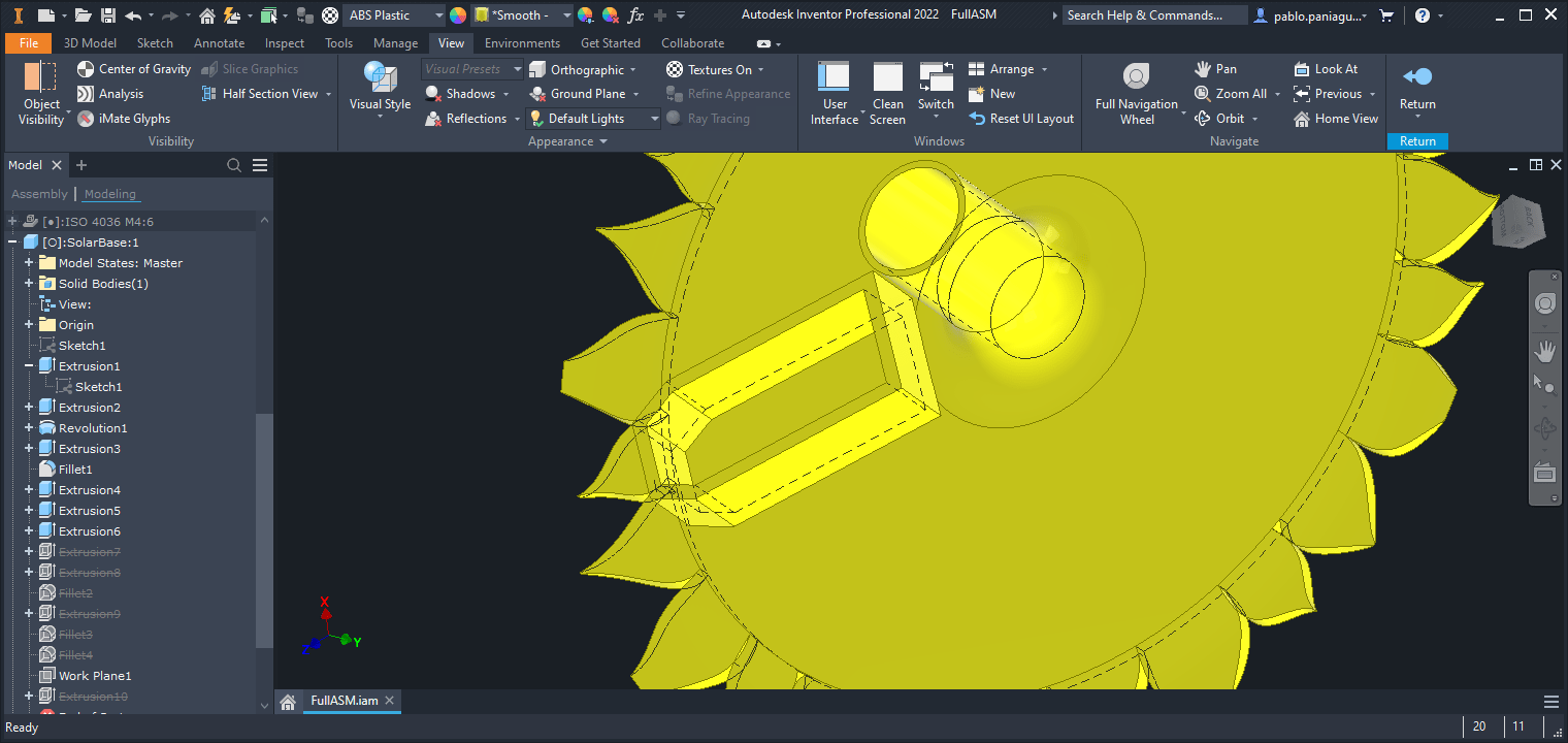
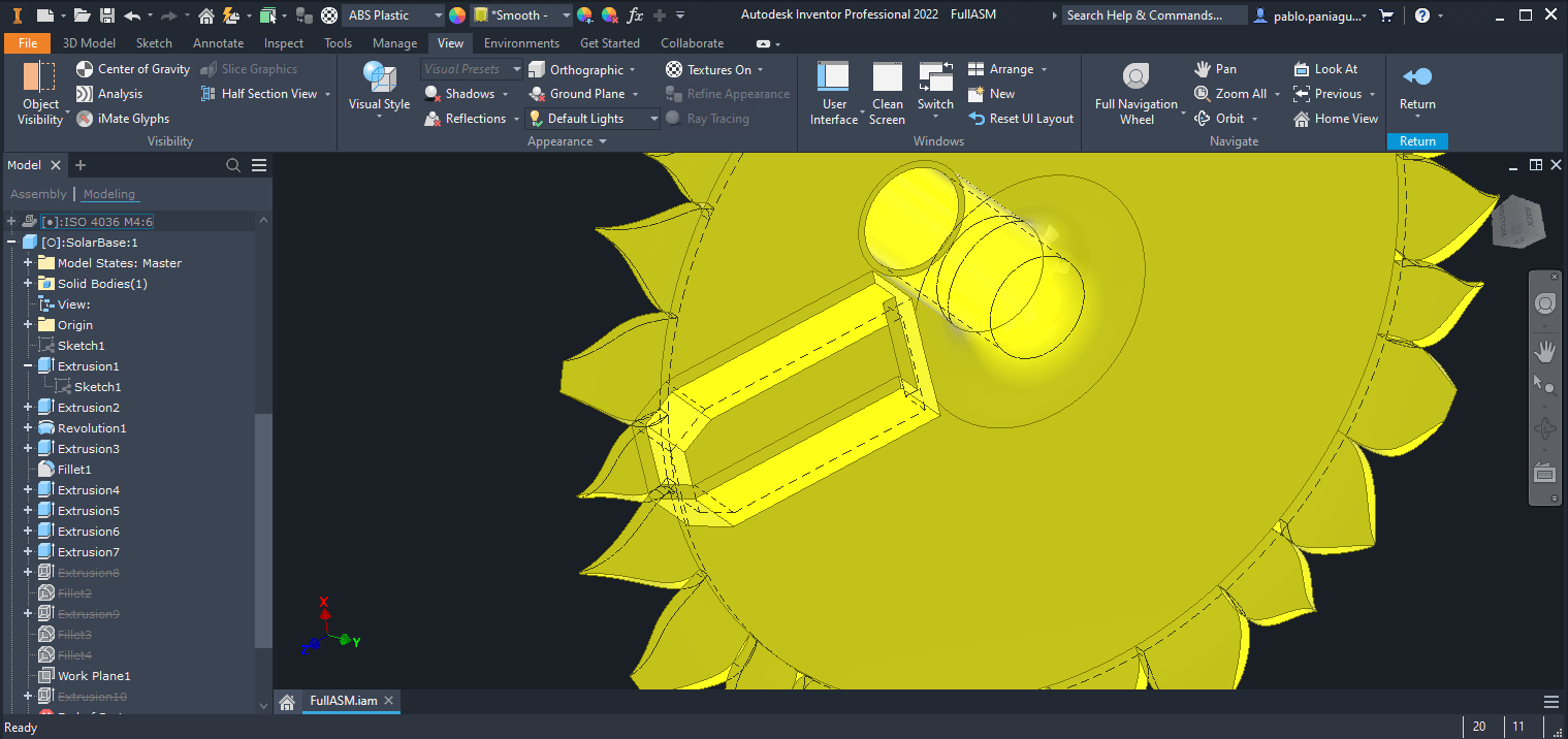
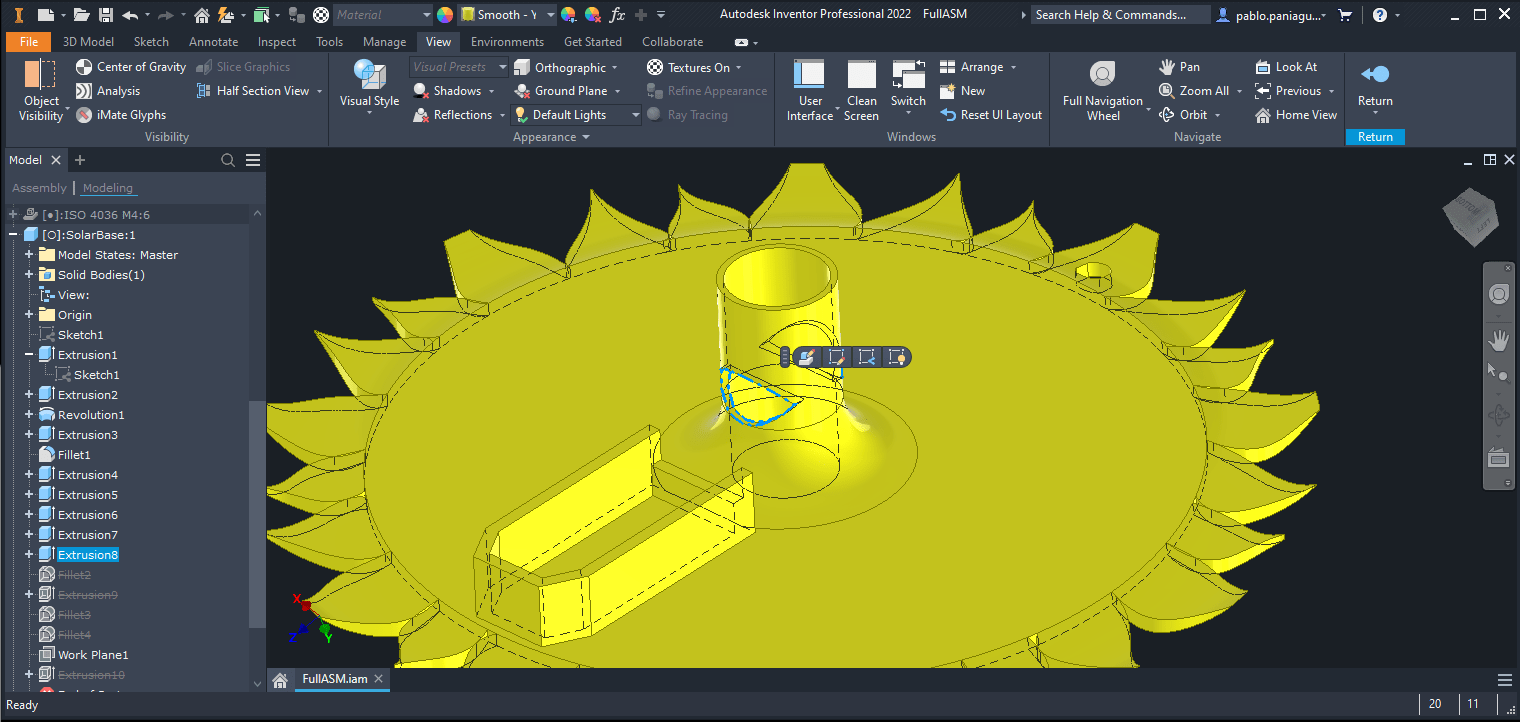
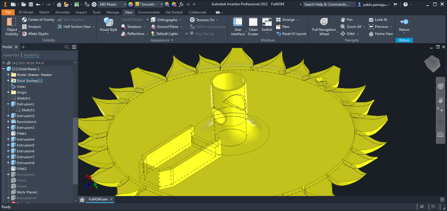
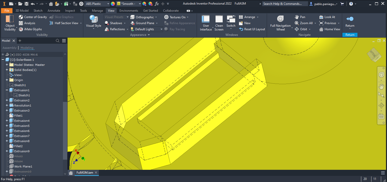
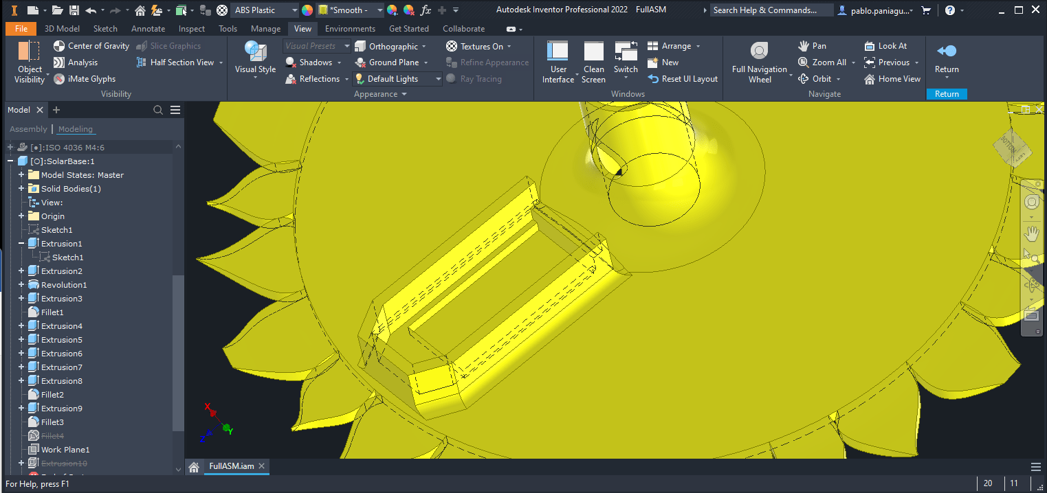
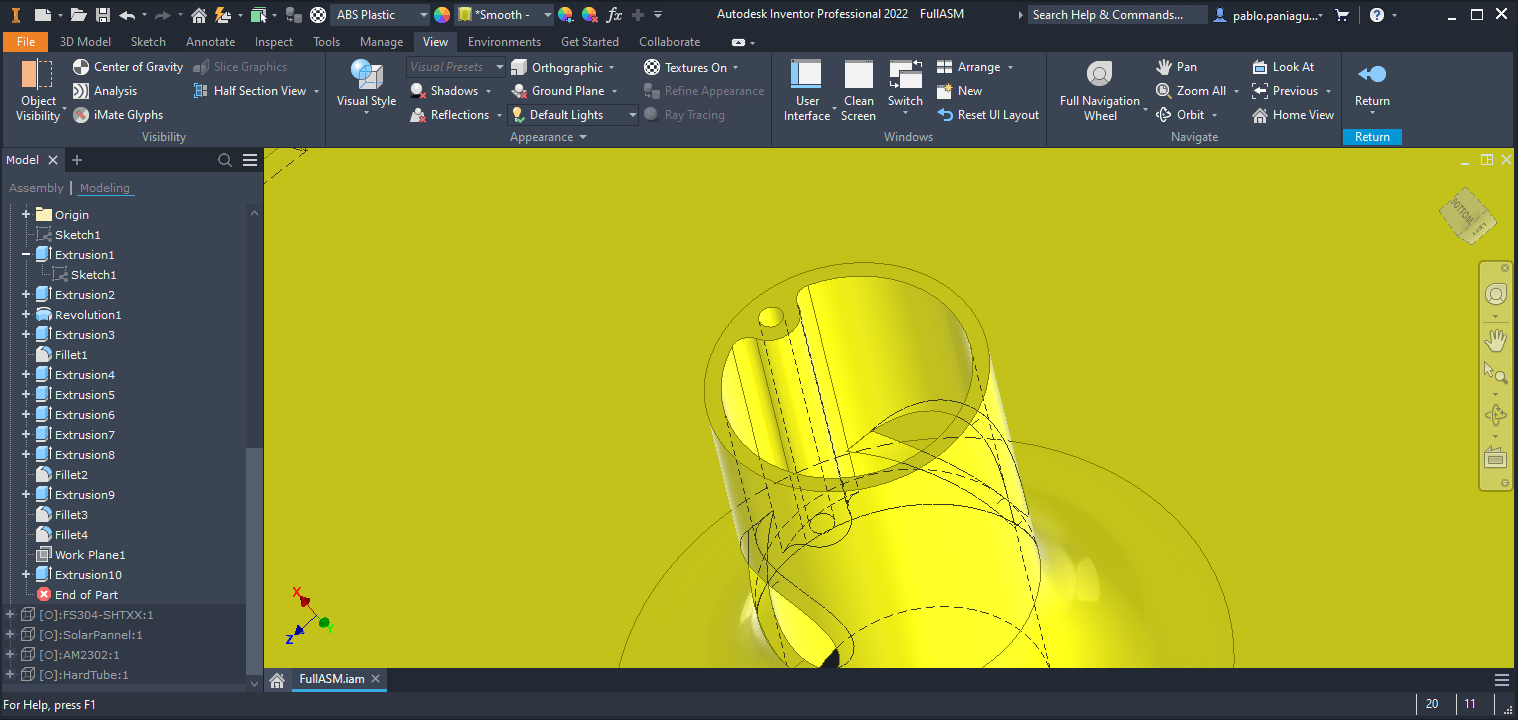
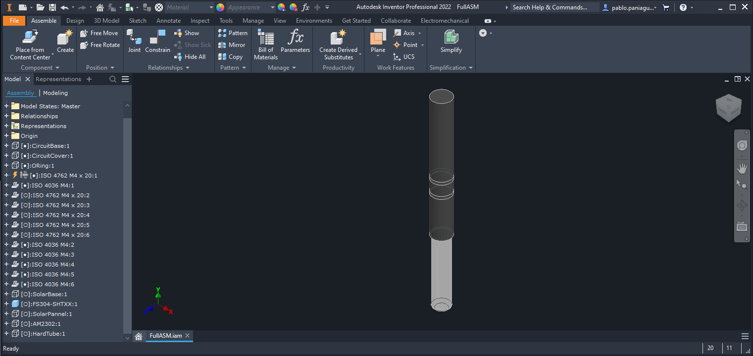
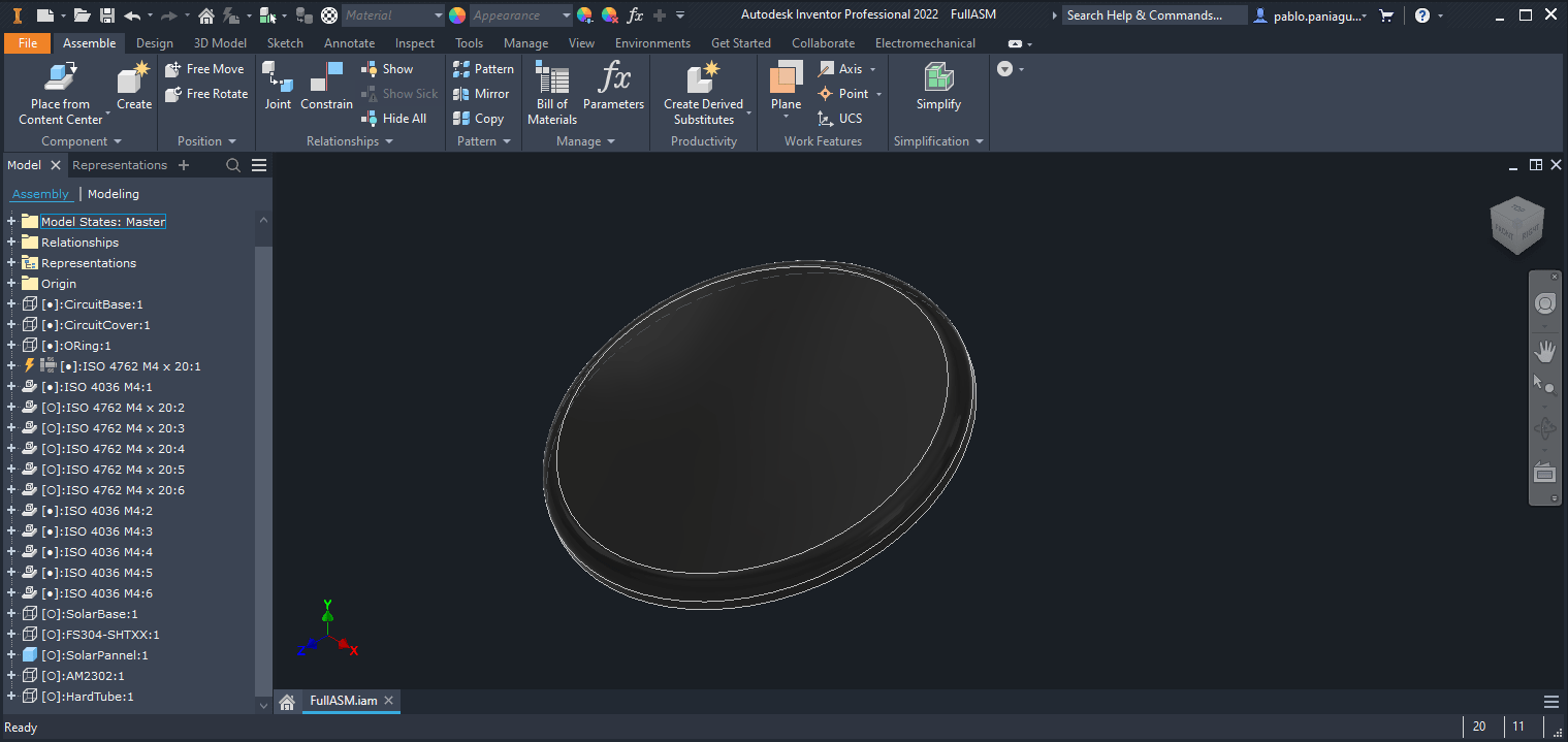
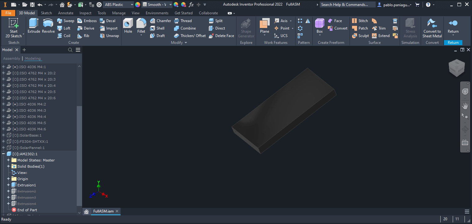
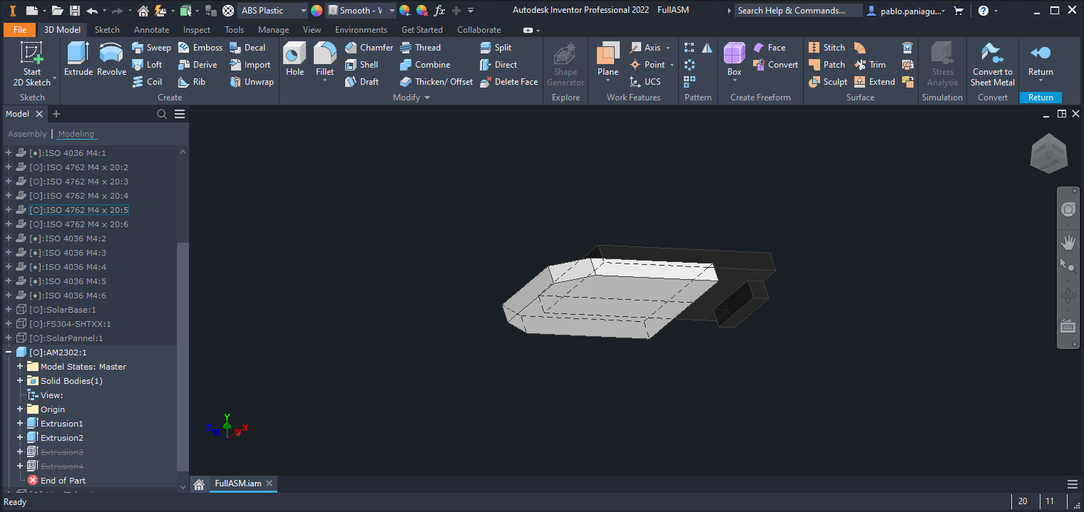
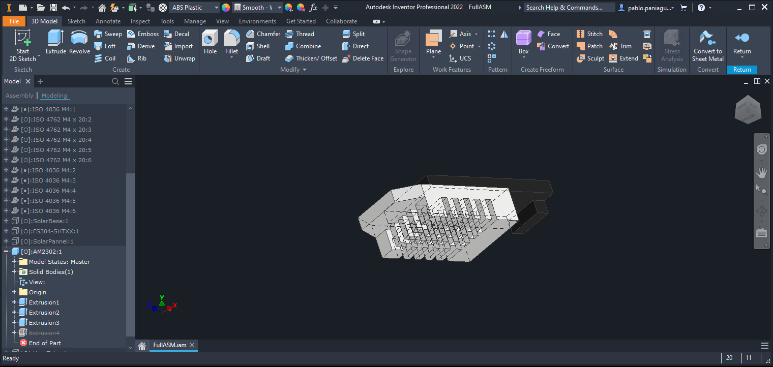
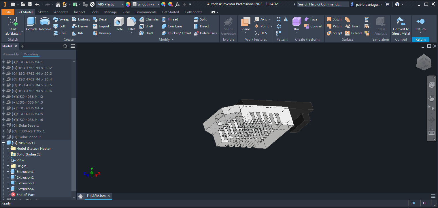
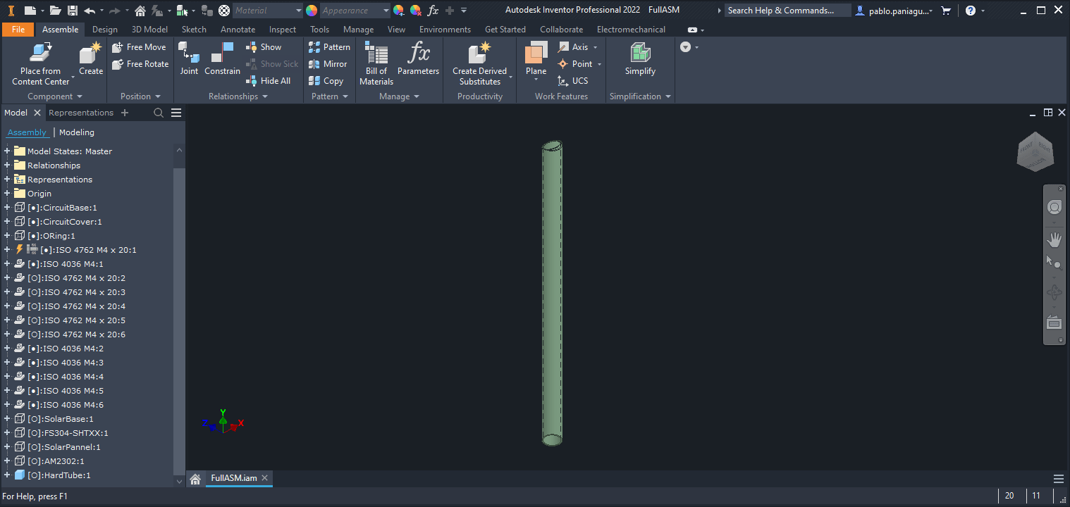
For this week I researched for the most used CAD softwares and compared their advantages and disadvantages, then I tested the ones that sound better to me and modeled the same piece to see how i liked or not the UX, then I selected one of them to model a piece for my final project.

CAD Software Comparison

Overall, the choice between these software packages depends on the specific needs and workflows of the user. Some are more suitable for specific industries, such as Inventor for mechanical design, while others focus more on collaboration and multi-user editing, such as Onshape. FreeCAD is a free option for those on a budget or those who require basic CAD functionality.

In my personal experience, At the end I used inventor, I know this tool pretty well and it’s like driving a bicycle to me. I just know where is everything and how it works. But I'll try to use Fusion 360 in this course to learn something new and also because many people that I know has made really good comments on it.

Fusion 360

  • Cloud-based platform, accessible from anywhere with an internet connection
  • Cloud-based platform, accessible from anywhere with an internet connection
  • Offers both CAD and CAM functionality
  • Designed for collaboration with its team sharing features
  • Subscription-based pricing model, with a free trial available
  • Has a wide range of integrated features and tools that cater to various design workflows.

Onshape

  • Cloud-based platform, accessible from anywhere with an internet connection
  • Offers both CAD and collaboration functionality
  • Designed for collaboration, with real-time multi-user access and simultaneous editing features
  • Subscription-based pricing model, with a free trial available
  • Provides real-time design analytics and version control tools.

Inventor

  • Desktop-based software, which requires a computer installation
  • Offers advanced simulation and engineering analysis capabilities
  • Can integrate with other Autodesk software products
  • Well-suited for mechanical and industrial design
  • Subscription-based pricing model.

FreeCAD

  • Free and open-source CAD software
  • Desktop-based software, which requires a computer installation
  • Offers basic CAD functionality, including 3D modeling, assembly creation, and drafting
  • Supports a wide range of file formats
  • Has a large community of developers, providing support and updates.

Final Project

For my final project i started working on a 3D flower by designing a sunflower which center is a solar panel and there is room for the battery and electronics on the bottom of the plant.

I also added a soil temperature and humidity sensor in the bottom and in the flipped side of the sunflower there is room for another sensor for environment humidity and temperature.

Bottom case

I started with the base of all the model. I measured and the MCU I wanted to use and the battery it needs to run and sized the case based on those measurements.

I extruded a rectangle with some holes for the screws and one hole in the middle for the temperature and humidity sensor.

Then I added a border to create a box where everything will sit.

Then I created a extrusion of a cylinder to enclose part of the sensor.

Then, so the sensor can be introduced to de ground more easily I used the chamfer tool to cut the border in an angle.

I used the fillet tool to round the edges of the box.

Then I extracted a rectangle extrusion so I can make later a o ring to seal the electronics against the weather.

I used the fillet tool to round the borders of the o ring channel.

Then I made an extrusion in each screw hole so the head of the screw can be flushed with the case.

Top case

For the top cover I started extruding with a rectangle and the six screw holes.

Then I extruded and cut some hexagonal shaped recesses so the screw nuts can be lased there.

Then I extruded again a rectangle with it’s corresponding six holes for the screws.

I extruded a rectangle to cover the holes and to close the electronics box and I left a hole at the top that will be used to pass the cables to the sensors on the flower.

To give it a better finish I used the chamfer tool to round all the external edges.

Finally, and just how I made it with the bottom part of the case I made a channel to place the o ring.

Then I created a cylinder to connect the bottom case with the flower on top

I also added a fillet to the border to make it stronger.

Finally, I added a shape with a hole in the center to add a wire and use it later to give the flower structure and mobility.

Then I used the inventor bolts and nuts tool to create the corresponding screws and fasteners.

O-ring

To create the o ring I simply made a rectangle and used the fillet tool on all of its borders.

Flower

For the flower I started extruding a simple design that using the revolve tool I repeated it so it created a circle.

Then I filled the center with a flat circle.

Then to give it a little more swag Using the revolve tool I cut the flower with a rounded flowery shape.

Then I created the cylinder to connect the flower with the bottom electronics case.

As I did with the bottom part, I added with the fillet tool a rounded edge to make it stronger.

Then I made a hole in one part of the flower so it can house in a photoresistor to measure light intensity.

Then I extruded the outer shape of the ambient temperature and humidity sensor.

I cut a little part of the border so the connector can fit.

Then I cut two holes on the center tube so the wires for the sensors may come out.

And to give the cylinder a little bit of more rigidity y used the fillet tool in the borders to round the holes.

Then I extruded a little step so the sensor may have a really snug fit.

To smooth everything up I added using the fillet tool a curve to all the edges where the sensor support merges with the flower

As in the bottom part, I added the support for the structure wire.

Ground temperature and humidity sensor

To create the soul sensor, I just extruded a bunch of cylinders on top of each other.

Solar panel

To create the solar panel, I just extruded a cylinder and used the fillet tool on one of its edges.

Ambient temperature and humidity sensor

To create the ambient temperature and humidity sensor I started with a simple rectangle of the PCB size.

Then I added the first part of the sensor.

And then the full size of the sensor simulating the grill that covers the electronics inside.

Finally, I cut a hole on the top of the sensor to make it as similar to the real one as possible.

Stem

To end the design, I extruded a big cylinder to simulate the plants stem.