WEEK 15
WILDCARD WEEK
Design and produce something with a digital fabrication process (incorporating computer-aided design and manufacturing) not covered in another assignment, documenting the requirements that your assignment meets, and including everything necessary to reproduce it. Possibilities include but are not limited to wildcard week examples.
15. Wildcard week
My Idea is to make knif with plasma cutter CNC machine we have in an other laboratory.
Our work will be divided into 4 parts: Presentation of the Plasma cutter in our Fab Lab, design of our model, generation of the cutting path and, finally, plasma cutting.

Presentation of the Plasma cutter in our Fab Lab
Presentation
A plasma cutter is a controlled machine that uses plasma cutting technology to cut all conductive materials. A plasma arc is formed when a gas, such as oxygen, nitrogen, argon or compressed air, is forced through the nozzle orifice. An electric arc generated by an external power source is then introduced to this high-pressure gas stream, more commonly known as a “plasma jet”. The plasma immediately reaches temperatures of up to 22,000°C, enabling it to cut very quickly. The role of the plasma cutter is to cut sheet metal quickly and relatively precisely, and to produce different shapes. Plasma can be used to cut metal sheets in thicknesses ranging from 0 to 160 mm, with a precision of plus or minus 0.2 mm.
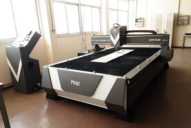
In our Fab Lab, we have a model HTP-1530 from HITECCNC compressed-air plasma generator up to 168A.
for the operation of the machine we have other additional devices:
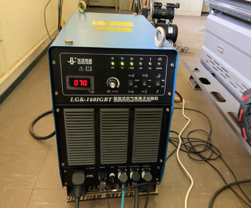
- A Huayuan LGK-160IGBT plasma source.
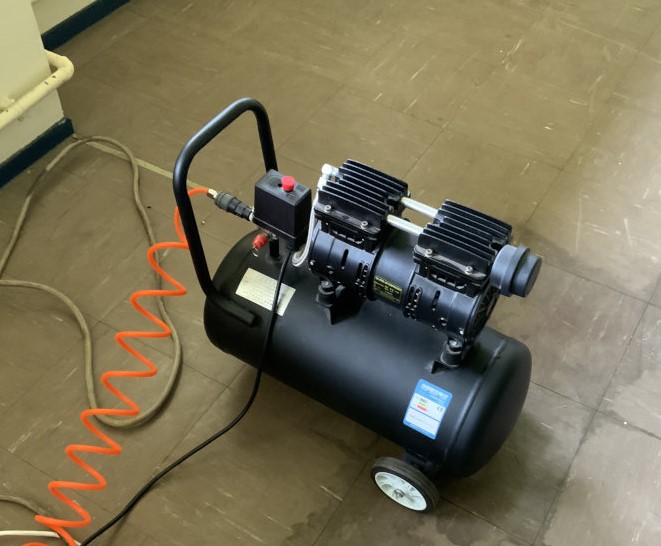
- Air compressor
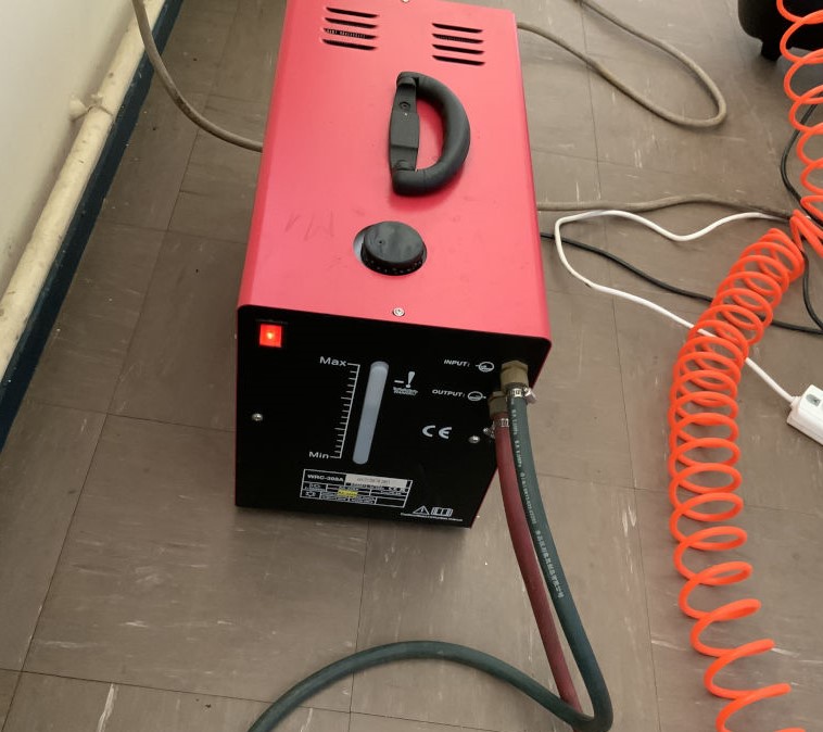
- Water pump station
Specification
| Brand | Hiteccnc HTP-1530 |
|---|---|
| Working area | 1500x3000mm |
| Power supply | Huayuan 160A |
| **Control system ** | CNC Starfire Control system with HYD Independent THC |
| Software | StarCAM |
| Resolution | ± 0.03mm |
| Command | G code (uoo,nc,mmg,plt) |
| Voltage | 380V, 3 phase,50/60HZ |
| **Consumble Parts ** | Cutting nozzle and electrode |
| Max working speed | 0-10000mm/min |
| Motor and driver | Leadshine stepper motor and driver |
Design
We designed our knife sketch with onshape :
I use arc tool to make the curve part
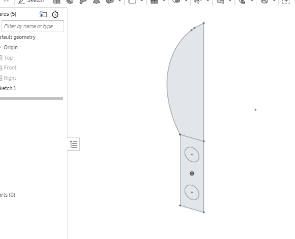
After we export our sketch into DXF file. then we go to the software with it.
Now we can proceed to the toolpath generator software for the plasma cutter. You can download the dxf file here.
Cutting path generation
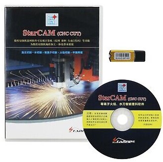
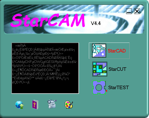
To generate the cutting path, we used the StarCAM software supplied with the machine.
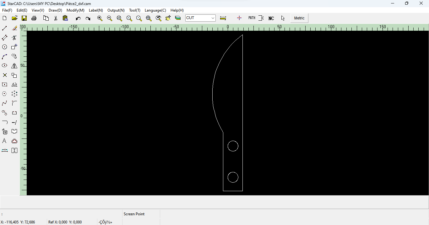
- First we open the software and click on StarCAD.
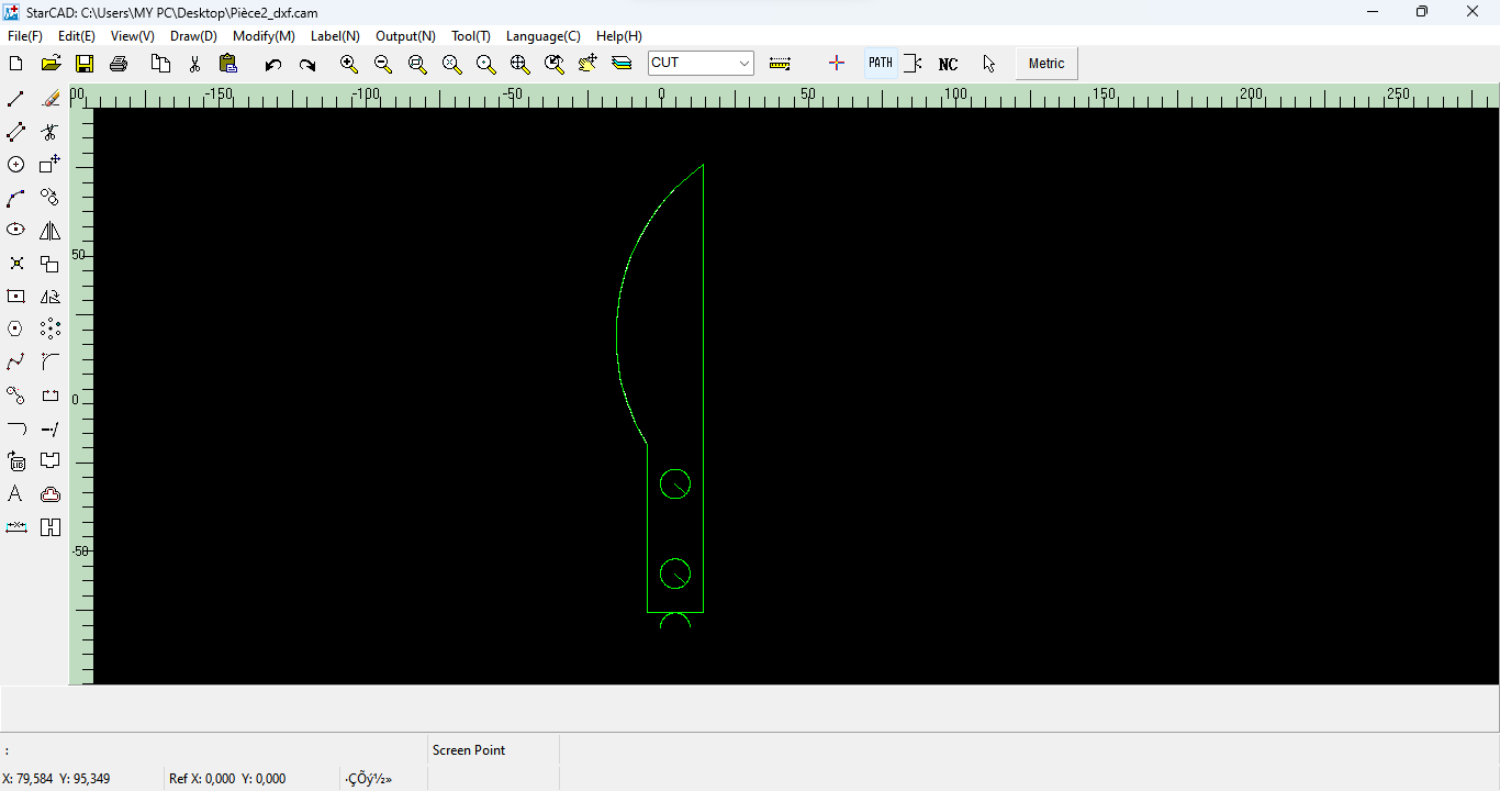
- Once StarCAD was open, we imported our DXF file as shown below
- Click on “Path” to generate the cutting path
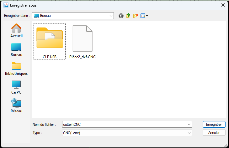
- click on “NC” to save it as shown below.
Once the cutting path has been generated, we can proceed to cutting. 😊😊✊
Find more details at this page
Cutting
Prior to starting any work on the machine, our initial step was to ascertain the machine settings, namely the arc current, arc voltage, cutting speed, and the suitable cutting nozzle. In order to accomplish this, we consulted the manufacturer-provided table presented below, which outlines the aforementioned parameters according to the thickness of the material to be cut.
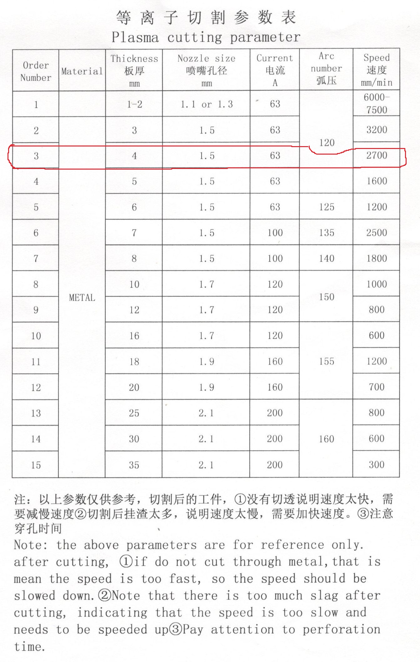
Given that our material is 4 mm thick, here are the parameters we have selected.
Cutting parameter
| Materiel | Metal |
|---|---|
| Thickness (mm) | 4 |
| Nozze size (mm) | 1.5 |
| Current (A) | 63 |
| Arc number | 120 |
| Speed (mm/min) | 2700 |
To start cutting we proceed as follows:
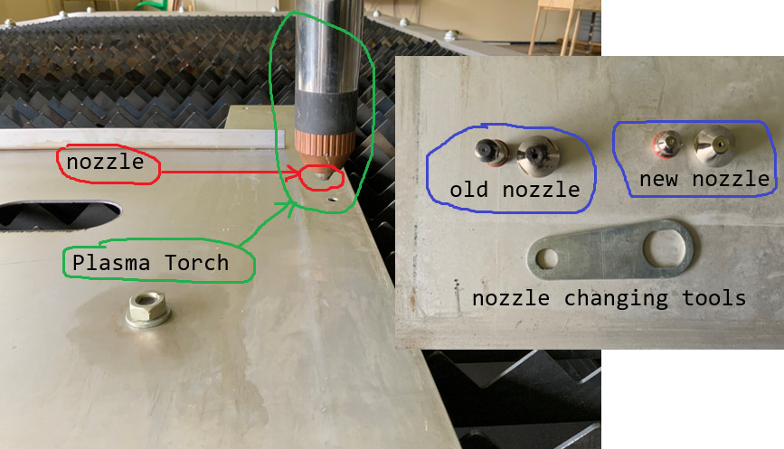
- First, we changed the nozzle as shown below
-
switch on plasma source, air compressor and water pumping station.
-
we set the plasma source to 63A as recommended above
-
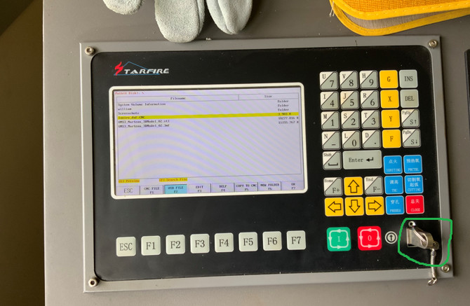
we inserted the USB key containing the cutting file into the plasma cutter’s control panel as shown below
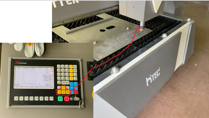
- we correctly positioned the plasma torch using the direction buttons as shown below
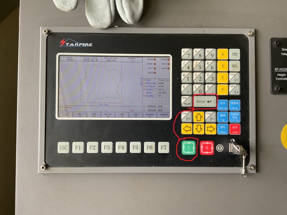
- Finally, we launched the cutting process with the green button as shown below and then pressed the “enter” button.
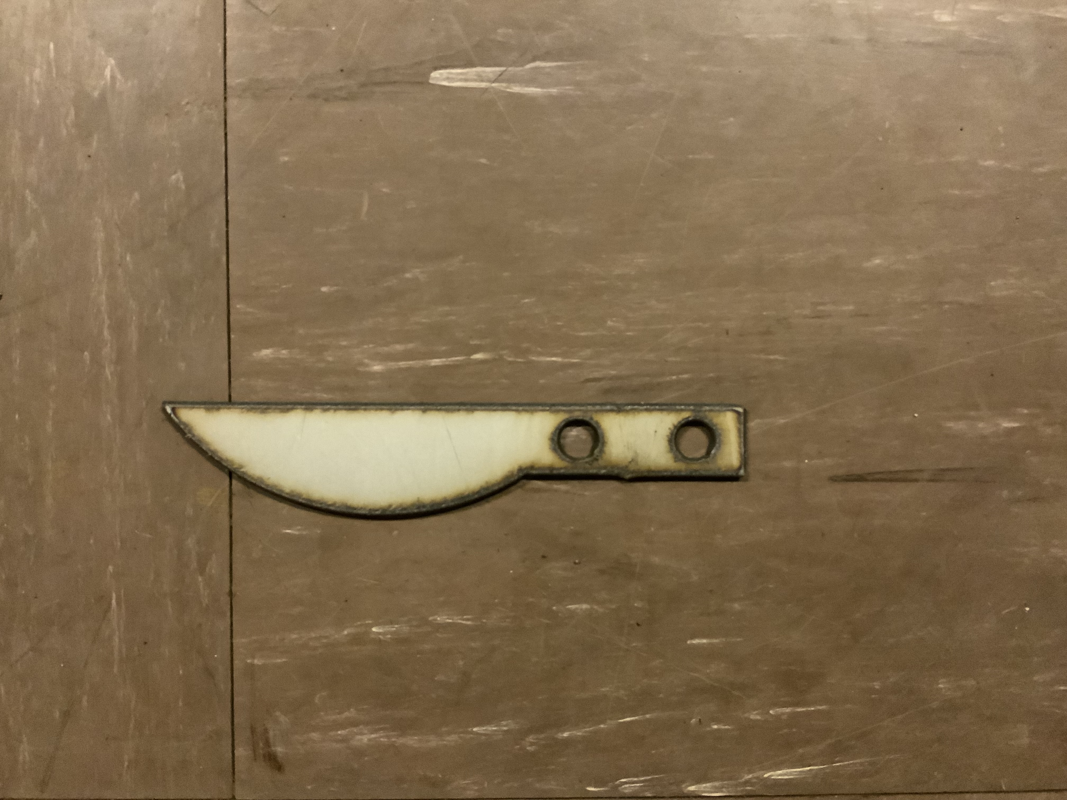
- The final result is
What we have leaned
This week we learned about how a plasma cutter works. As we learned from the documentation, the main principle of a plasma cutter is the generation of plasma through an electric arc and water, followed by the expulsion of the plasma using air. This expelled plasma is collected in a tank, allowing precise cutting. It is crucial to note that the cutting process never starts directly on the desired path. Instead, a small hole is first created before the actual cut begins.
Important
⚠️Don’t forget to wear safety glasses because of plasma cutter radiation.