WEEK 8
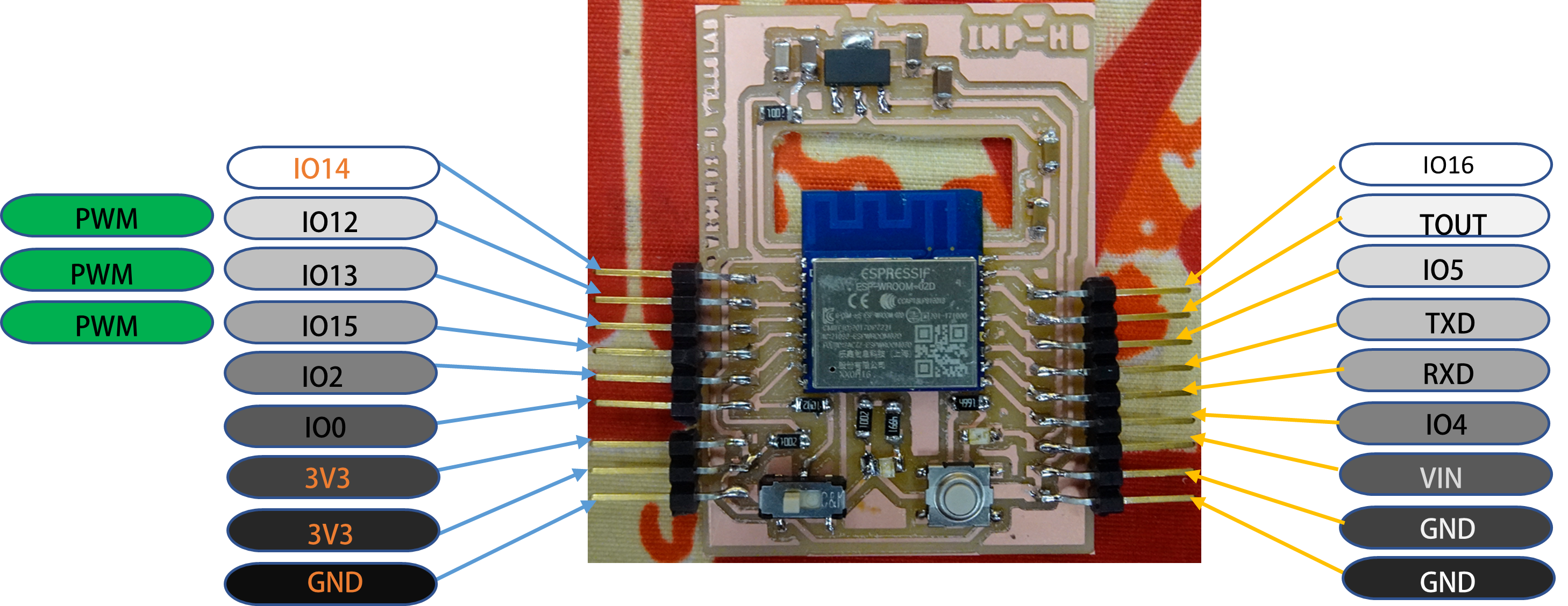
For this week assignment, I had to make my ESP-WROOM-02D development board which I will use for my final project.
Electronics production
Group assignment :
-
Characterize the design rules for your in-house PCB production process: document feeds, speeds, plunge rate, depth of cut (traces and outline) and tooling.
-
extra credit: send a PCB out to a board house.
-
Document your work to the group work page and reflect on your individual page what you learned
To see our group assignment click here
Individual assignment :
-
Make and test the development board that you designed to interact and communicate with an embedded microcontroller
-
extra credit: make it with another process.
Previously on using Eagle in week 6, We have designed our board.
Now with MonoFab Roland SRM-20 in our fablab, we are going to make our development board using the files availabe in week 6 assignment at the end of the page.
So to make our board follow this steps :
Generate .png file from Autodesk Eagle. First we need the path traces then the board outside.
generate circuit paths
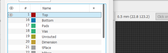
click on layer settings 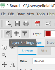
hide all layer and check Top only

Now export png file as shown below :
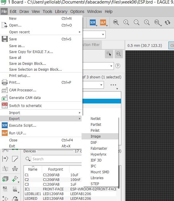
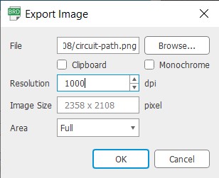
don't forget to check monochrome*
generate outside
Do the same process by choosing Dimension layer.
1. Mods CE
To open mods CE type mods CE mit on the search bar or just click on this link.
right click on the page.
step 1
choose programs and open programs after.
step 2
choose pcb in Roland>SRM-20 mill.
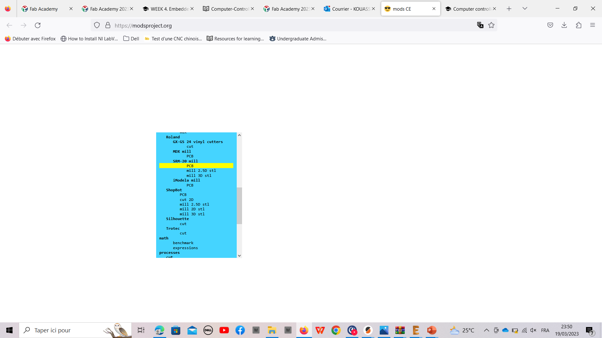
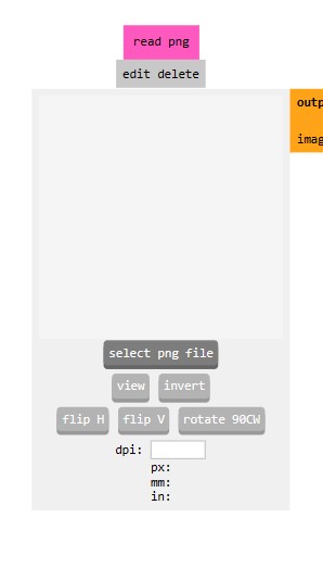
step 3
Upload your file by selecting “select png file” as shown below.
These are two files to upload :
 outside
 circuit path
Now set all other settings
Tips
-
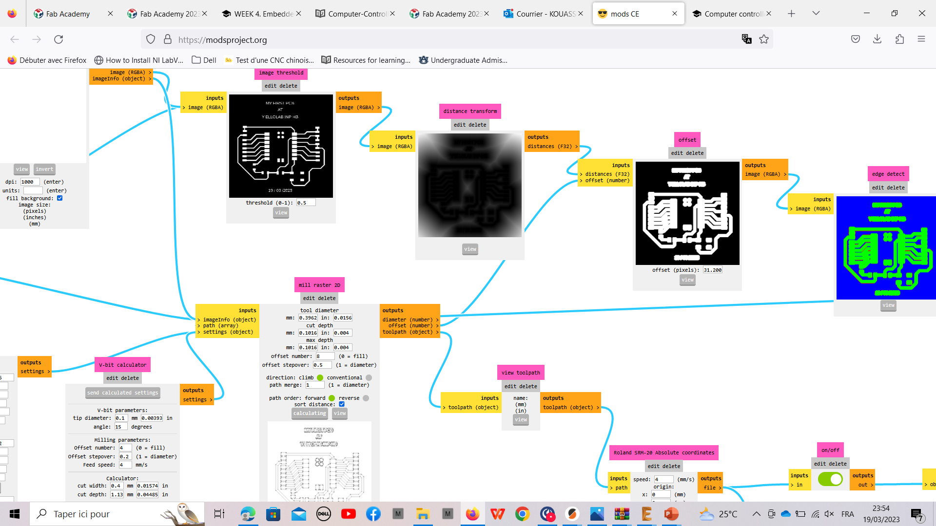
for traces, click on
mill tracesinset PCB defaults modulethen go toRoland SRM-20 Absolute coordinatesmodule and set x y and z to 0mm and injob heightsection, set z to 4mm. Check if the twoinputs/outputsmodules in front are checked. last go tomill rastermodule and click on calculate. -
Do the same for outside but it’s necessary to invert the colors in
read pngmodule and go to click onmill outlinebefore calculate.
After calculated you should have .rml file downloaded. With these files we get to the machine by using Vpanel for SRM20 software.
2. Vpanel software and ROLAND machine
Make your files accessibles to load them in the software then open software.
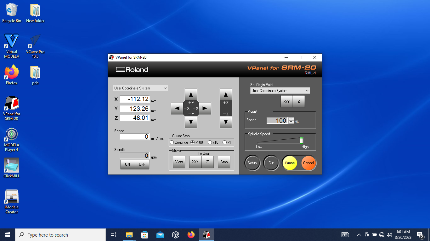
when vpanel is opened turn on your machine set the speed approximately at its medium and click on “on” in vpanel, to run the machine without milling for 10 min to get it ready.
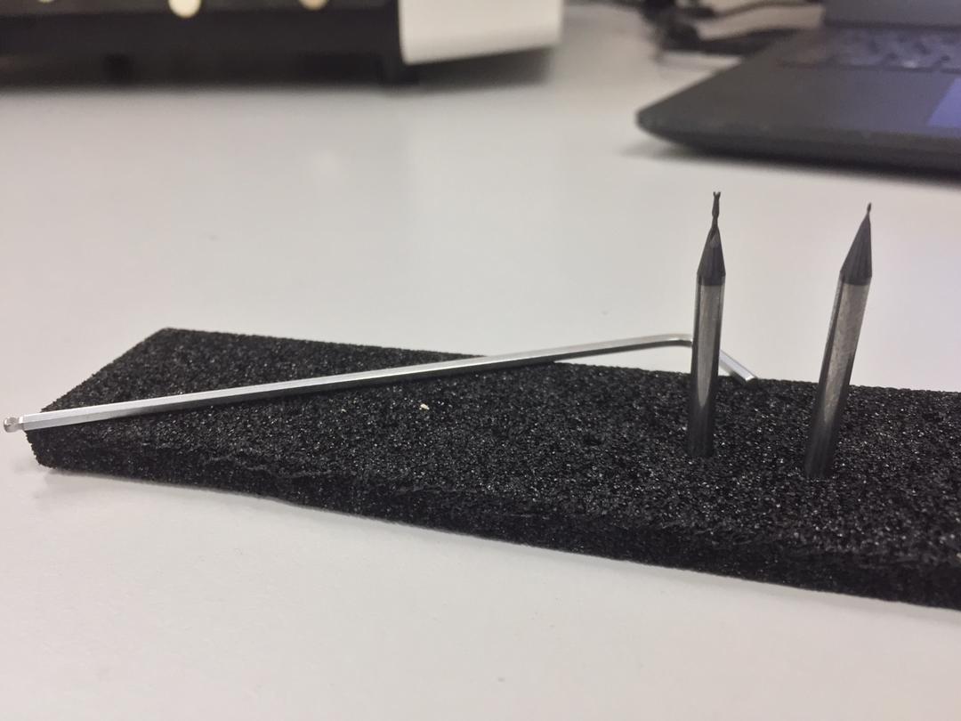
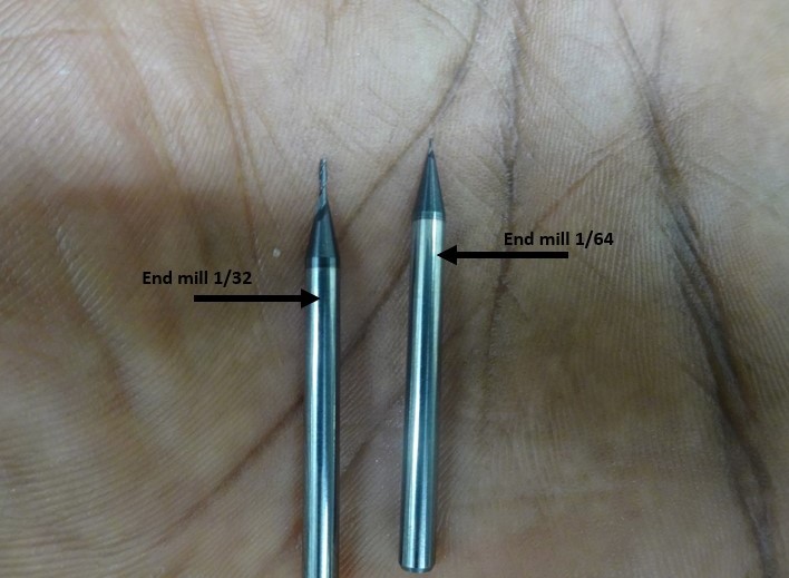
prepare the machine by putting your right tool in the spindle. the first is 1/64” for trace and the other is 1/32” for the outline
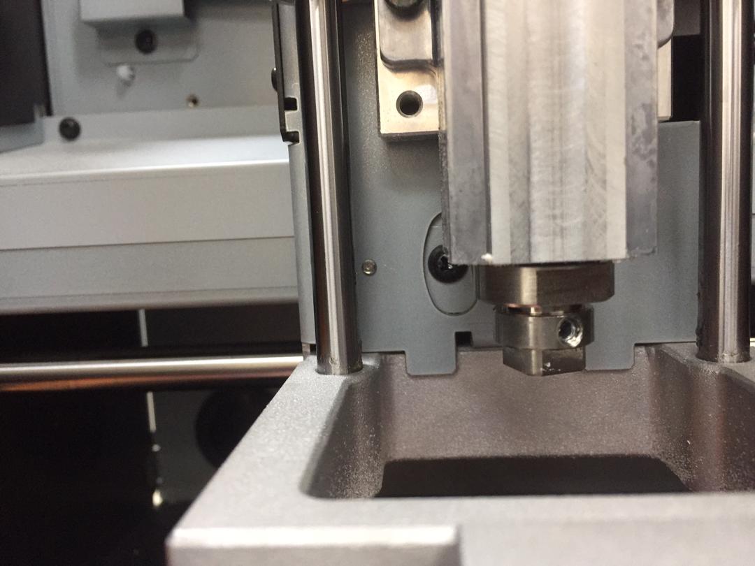
After that, go back to the software and set the different origins. choose the origins according to the space available on the copper plate placed naturally in the machine to mill it.
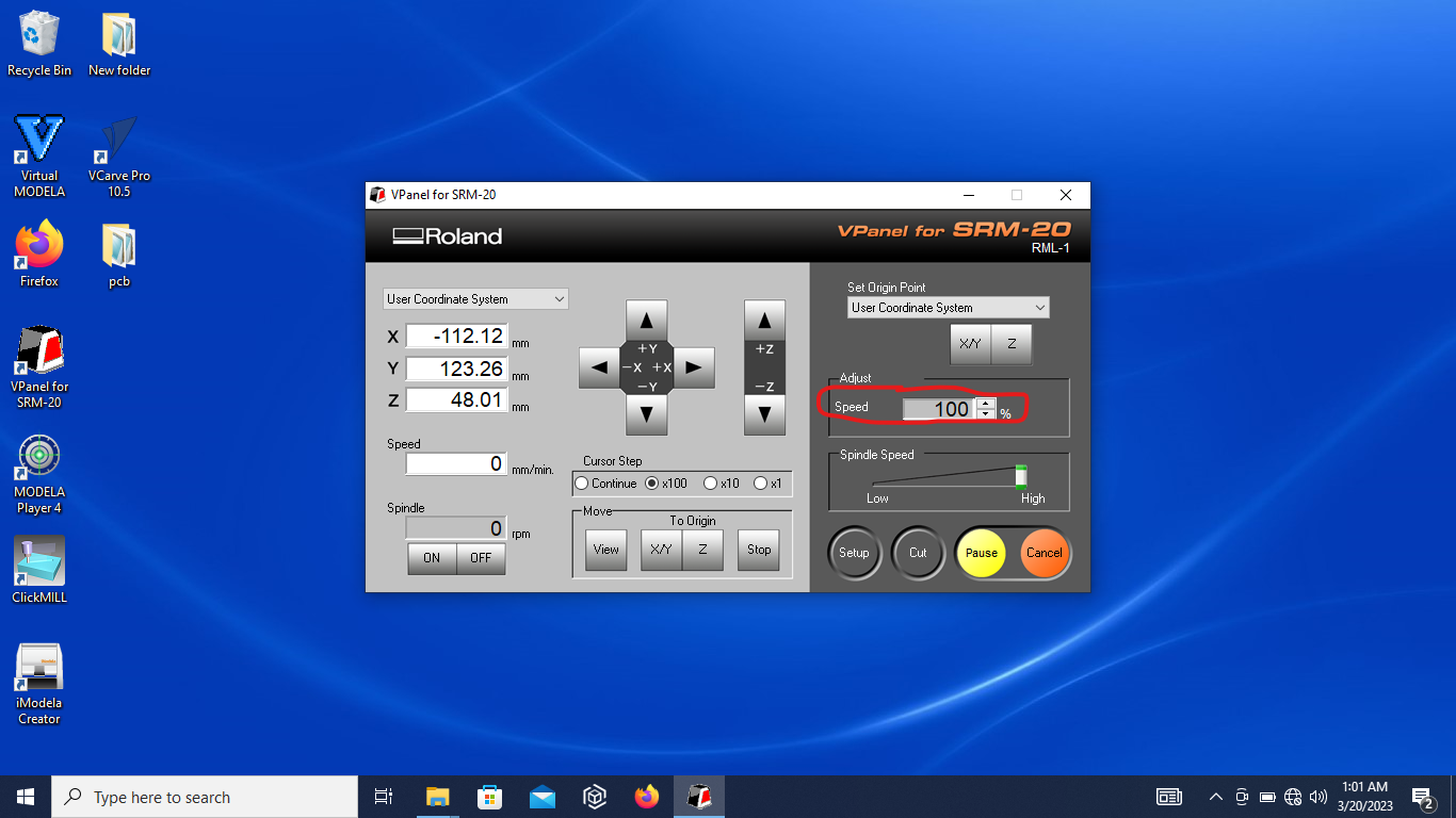
After that, load your files as shown in the following images :

after all settings cick on X/Y button.
Load your file : my files

then start working by clik on cut.
So I set the speed to 90% then to 100% during the milling
Finally I had to redo my work cause I encountered issues when I was testing my board. I was unable to upload code to my development board
Hence I restart the board design after detect the problem that was an error in the circuit for flash boot mode and UART download mode of my board chips. The design is available in week 6 assignment.
Then I restart the same process to make my board. But I also encountered another trouble when I was milling my board hence I accidentally broke our 1/64” tool during milling traces cause I increase the speed of spindle movement too much. I set it to 90 % after to avoid problem during the milling.
3. Soldering
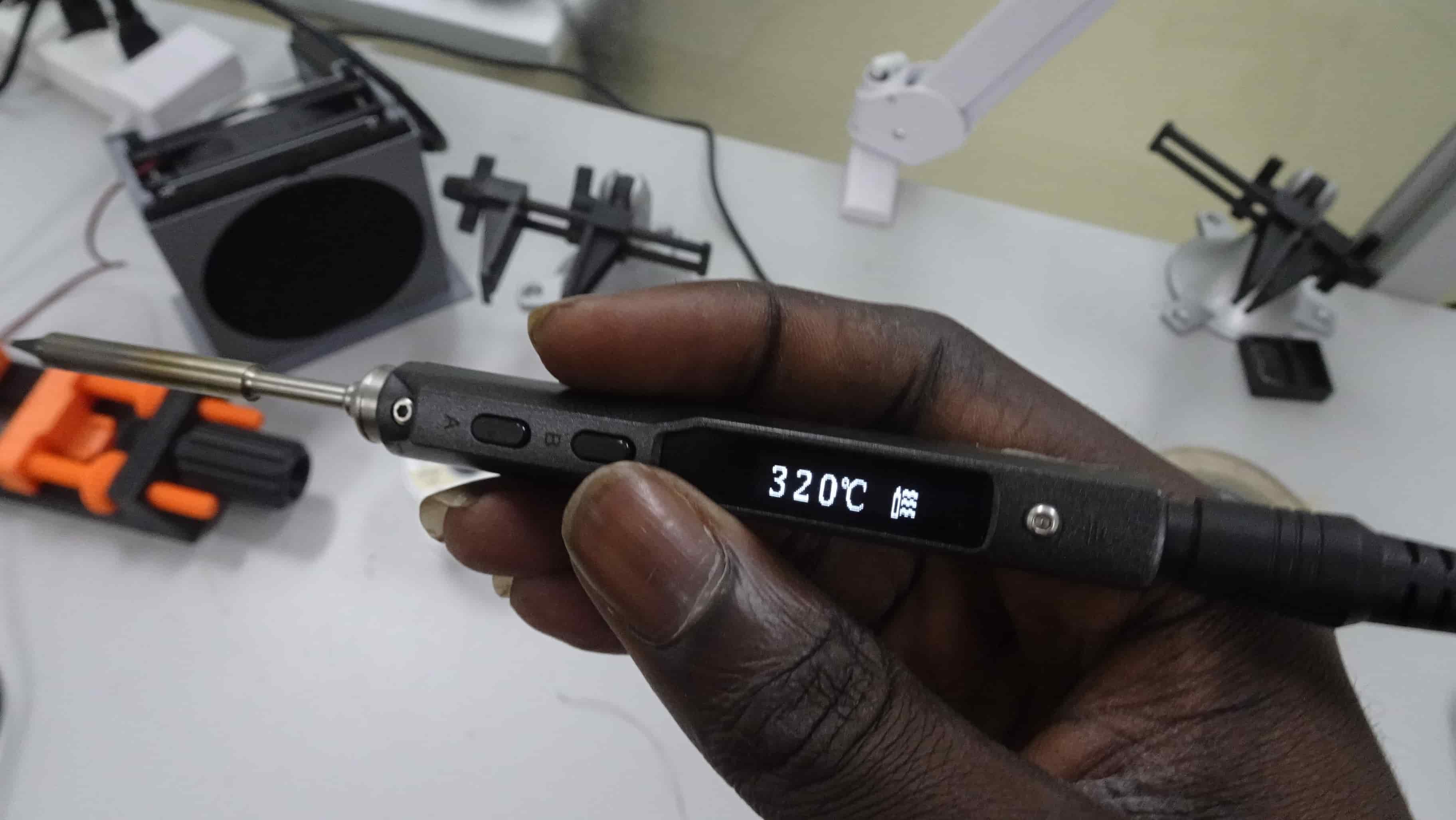
We use the soldering iron at 320°C. Make sure you use a thin tin otherwise, you will leave excedent tin on the board and risk to short circuit the components.
Before soldering clean the iron put a smal bit of tin on the iron then weld one paw of the component then the other.
Make sure you begin by the most complex component to weld. Hence it’s preferable to weld the mcu first.
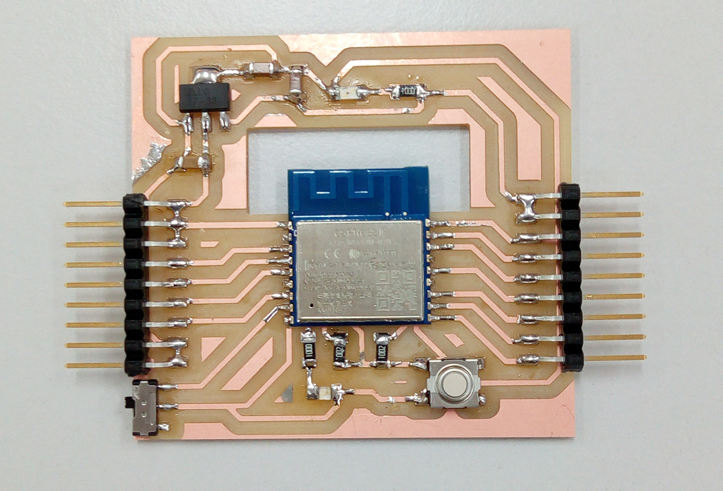
The image below show the new one I call it SMITY BOARD
here are my files you can download
3. Test
workflow to program my board
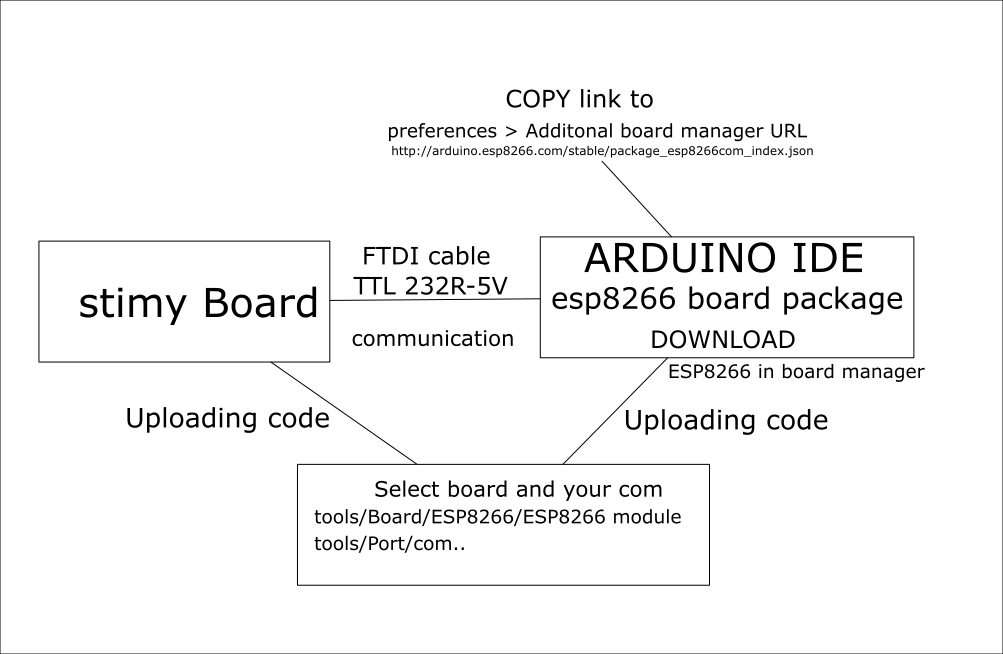
copy link : http://arduino.esp8266.com/stable/package_esp8266com_index.json