WEEK 9
For this week assignment I worked with LCD as OUTPUT. I’m working with a LCD for my final project thus I’m going incoporate the work in this week.
OUTPUT DEVICE
Group assignment:
-
Measure the power consumption of an output device.
-
Document your work on the group work page and reflect on your individual page what you learned.
Individual assignment:
- Add an output device to a microcontroller board you’ve designed and program it to do something.
Learning outcomes :
- Demonstrate workflows used in controlling an output device(s) with MCU board you have designed.
What is LCD !
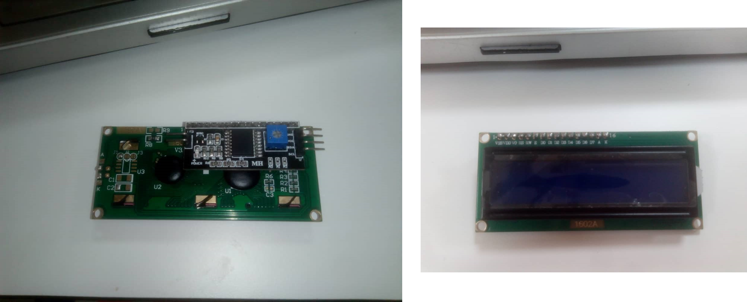
Liquid Crystal Display or LCD is a flat, electronic device generally used as a screen in televisions, computers, smartphones and display signs for producing still and movable images.
As the name goes, LCD is composed of liquid crystal particles. Liquid crystals generally do not emit light on their own rather they are illuminated by a fluorescent backlight.
Liquid crystals were discovered back in the 1800s and over the following years underwent several modifications that deemed them suitable for a wide variety of applications. (proide by https://www.electronicsforu.com/)
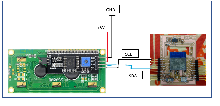
To get the LCD working, I simply use a I2C module to control it with stimy board I made.
Programing workflow
wiring components
According to the stimy board pinout and also the WROOM 02D chip pinout as shown below
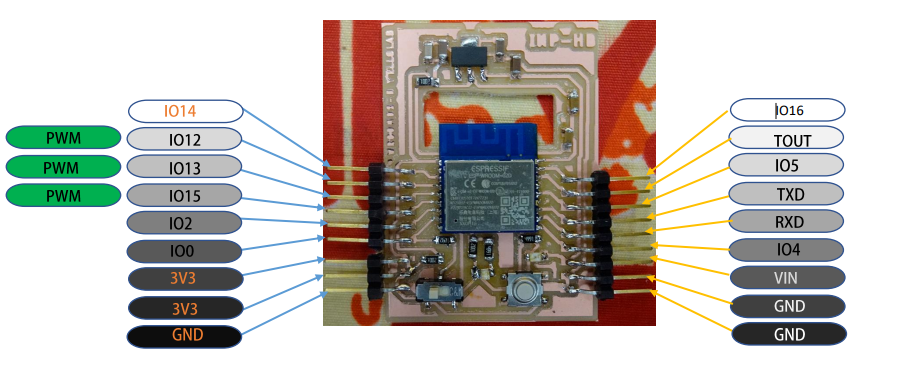
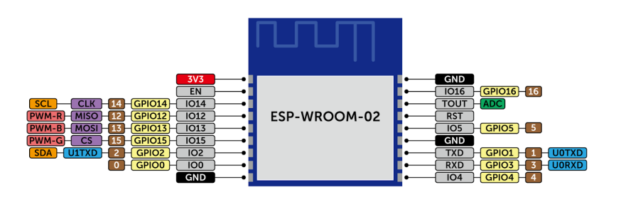
this is how the different component are wired.
Programming
Download LiquidCrystal_I2C library and use sample code SerialDisplay
To program our board we use ftdi cable.
In the IDE we choose in tools Generic ESP8266 as board.
If you don’t have download board for esp8266 yet then go to the preferences and check if you’ve already added this =url= : http://arduino.esp8266.com/stable/package_esp8266com_index.json in Additional boards manager URLs.
then go to boards manager in tools>Boards to instal esp8266 board by typing it in the searchbar.
Unfortunately I was unable to program my LCD with my board based on ESP8266 wroom02D maybe due to the I2C communication of the chip wich is not compatible with the library “wire.h”
So I decided to control a Servo motor with my board.
The servomotor will complete a 180° rotation cycle while returning to its starting position at the end of each cycle. We added an LED which turns off when the servomotor performs its rotation cycle.
We have also a button which is pushed to stop the rotation cycle and pushed again to restart the cycle. And when the rotation cylce is stopped the LED turns on.
I provide below the source code :
the differents components are wired with the board like this :
| Servomotor | led | button | board |
|---|---|---|---|
| data | - | - | 13 |
| GND | K | GND | GND |
| VCC | - | - | +3V |
| - | A | - | 15 |
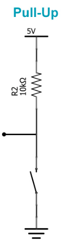
| - | - | INPUT | 12 |
The button is connected with pull up resistor as illustrated in the picture below
I provide link to my electronics design and production to get all informatioon about my smity board. week06 week08
#include "Servo.h"

const int  button = 12;
const int led = 15;
bool ledstate = 0;

Servo monservo;


void setup() {
  // put your setup code here, to run once:
  Serial.begin(9600);
  monservo.attach(13);
  pinMode(led,OUTPUT);
  pinMode(button,INPUT);
}

void loop() {
  // put your main code here, to run repeatedly:
  int buttonstate = digitalRead(button);
  if(!buttonstate)
  {
    ledstate = 1-ledstate ;
  }
  while(!button)
    buttonstate = digitalRead(button);
  if(!buttonstate)
  {
    digitalWrite(led,ledstate);
    for (int i = 0; i < 180; i++) {
    monservo.write(i);
    delay(5);
    }
  }
  else{
    digitalWrite(led,ledstate);
      if(ledstate==0)
      {
        for (int i = 180; i >0; i--) {
        monservo.write(i);
        delay(5);
      }
    }
  }
  Serial.println(ledstate);
  }
Explaining code
#include "Servo.h" Include Servo.h library
Define different pins we will use variable and object of the library Servo.h
const int  button = 12;
const int led = 15;
bool ledstate = 0;

Servo monservo;
In the Setup I specified how I will use my pins and which pins will control the servomotor.
void setup() {
  // put your setup code here, to run once:
  Serial.begin(9600);
  monservo.attach(13);
  pinMode(led,OUTPUT);
  pinMode(button,INPUT);
}
In the loop function the main code will be executed.
void loop() {
  // put your main code here, to run repeatedly:
  int buttonstate = digitalRead(button);
  if(!buttonstate)
  {
    ledstate = 1-ledstate ;
  }
In the begining I ask buttonstate if the button is pressed the state is low else it’s high so we bascul the value of ledstate variable.
  while(!button)
    buttonstate = digitalRead(button);
I have Insert In my code this part to examine the button state to up the variable buttonstate to date.
  if(!buttonstate)
  {
    digitalWrite(led,ledstate);
    for (int i = 0; i < 180; i++) {
    monservo.write(i);
    delay(5);
    }
  }
  else{
    digitalWrite(led,ledstate);
      if(ledstate==0)
      {
        for (int i = 180; i >0; i--) {
        monservo.write(i);
        delay(5);
      }
    }
  }
  Serial.println(ledstate);
  }
If buttonstate is false that means button is pressed so the motor rotate from 0° to 180° and the led is on because ledstate is true.
to turn off the LED we must push the button during a certain time because of delays in the code. then the servomotor start its cycle of rotation.