WEEK 4
EMBEDDED PROGRAMMING
Group assignment :
- Compare the performance and development workflows for other architectures.
To see our group assignment click here
Individual assignment :
-
Browse through the data sheet for your microcontroller.
-
Program a microcontroller development board to interact and communicate.
-
Extra credit: use different languages &/or development environments.
We’ll use “Seeed studio XIAO RP2040” card as a development card.
Presentation
Seeed Studio XIAO RP2040 is a microcontroller using the Raspberry RP2040 chip. It runs at up to 133 MHz, is built with rich interfaces in a tiny thumb size, and fully supports Arduino, MicroPython, and CircuitPython1. The XIAO RP2040 is an Arduino-compatible microcontroller featuring the Raspberry Pi Pico RP2040 chip. with a size of 20 x 17.5 mm it’s suitable for small projects and portable thanks to its low power consumption.
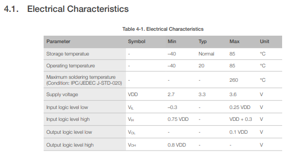
Browsing the datasheet
In the datasheet we found useful information that allowed us to control our microcontroller and safely.
1. Technic specifications
| Item | Value |
|---|---|
| CPU | Dual-core ARM Cortex M0+ processor up to 133MHz |
| Flash Memory | 2MB |
| SRAM | 264KB |
| Digital I/O Pins | 11 |
| Analog I/O Pins | 4 |
| PWM Pins | 11 |
| I2C interface | 1 |
| SPI interface | 1 |
| UART interface | 1 |
| Power supply and downloading interface | Type-C |
| Power | 3.3V/5V DC |
| Dimensions | 20×17.5×3.5mm |
get more info here.
Seeed Studio XIAO RP2040 pinout
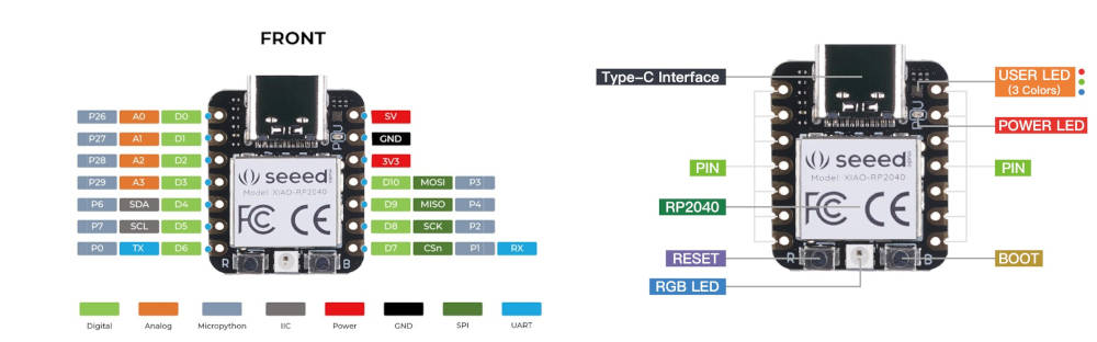
1. The schematics of the development board.

download the diagram here
Programming
for the programmimg of Seeed studio XIAO RP2040 card we used arduino IDE and the following components :
- SERVO motor
- Seeed studio XIAO RP2040 development board
- 3 wires
ARDUINO IDE
Use this link to get Arduino IDE 1.8.19 version.
you should have the requested informations in above link to make ready the software to program the board.
now let’s start the programming.
before all let’s see the board pinout

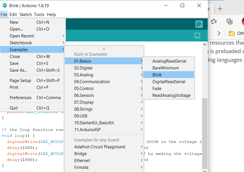
before programming let’s upload the blink code to make sure all is good. go to : File>Examples>Basics>Blink as shown below
Note
I was encountered a problem to select the port and to fix it I created a new text file that I called NEW and I gave .UF2 extension. that fixed all my problem.
Then I choosed the port to upload code
Now we will upload code to control a servo-motor
/* Servo motor with Arduino example code. Position and sweep. More info: https://www.makerguides.com/ */

// Include the servo library:
#include <Servo.h>

// Create a new servo object:
Servo myservo;

// Define the servo pin:
#define servoPin D0

// Create a variable to store the servo position:
int angle = 0;

void setup() {
  // Attach the Servo variable to a pin:
  myservo.attach(servoPin);
}

void loop() {
  // Tell the servo to go to a particular angle:
  myservo.write(90);
  delay(1000);
  myservo.write(180);
  delay(1000);
  myservo.write(0);
  delay(1000);

  // Sweep from 0 to 180 degrees:
  for (angle = 0; angle <= 180; angle += 1) {
    myservo.write(angle);
    delay(15);
  }

  // And back from 180 to 0 degrees:
  for (angle = 180; angle >= 0; angle -= 1) {
    myservo.write(angle);
    delay(30);
  }
  delay(1000);
}
Tip
Some USB cables can only supply power and cannot transfer data. If you don’t have a usb cable or don’t know if your usb cable can transmit data, you can check seeed USB type C support USB 3.1.
Another board we design
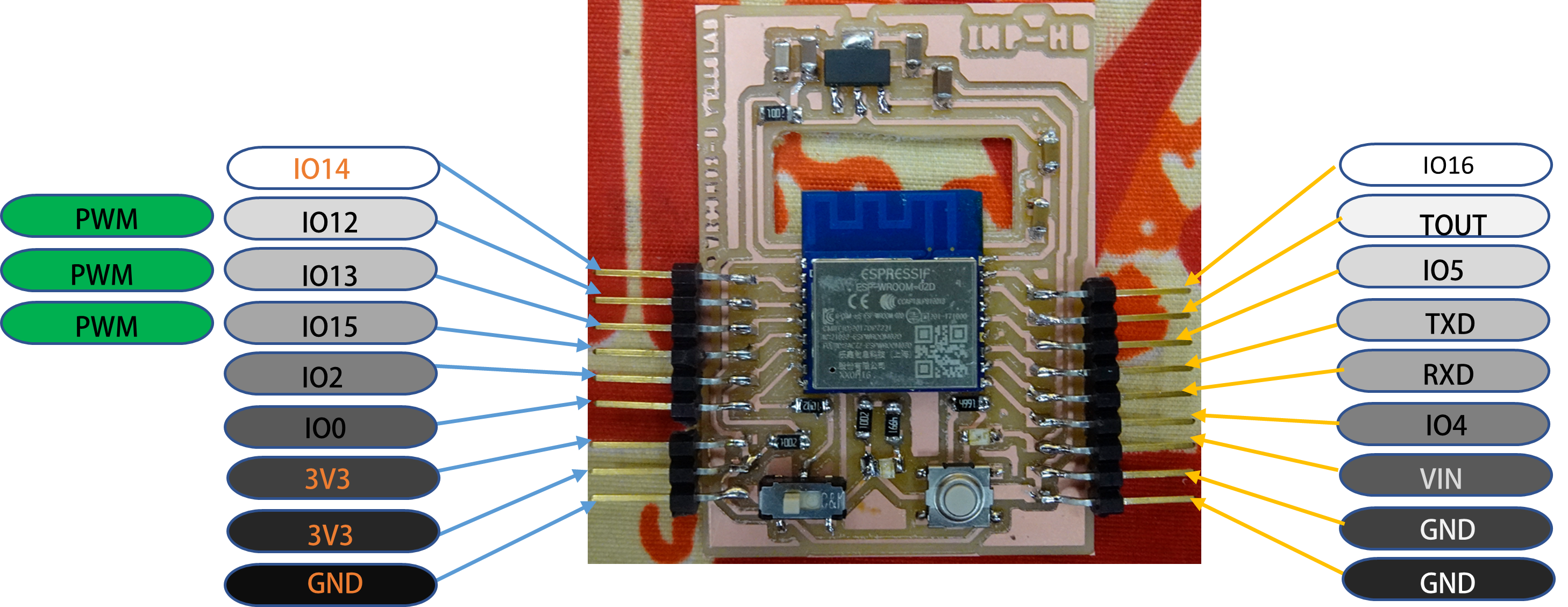
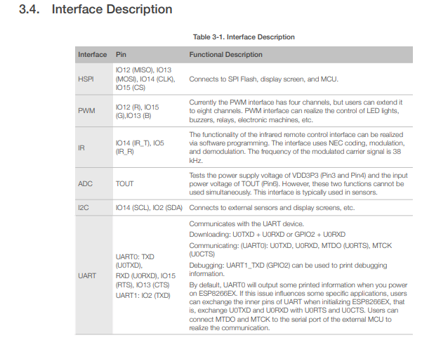
The chip mounted on this board is the ESP8266 wroom 02D. More details about the board are available on these links Week 6 : Electronics design and Week 8 : Electronics production From the datasheet of the chip we noticed some informations.
Programming
We programmed our board with the Serial event example of the arduino IDE that we modified.
This is code :
// Serial event example modified I turned led on according to its color

String inputString = "";      // a String to hold incoming data
bool stringComplete = false;  // whether the string is complete
const int blueled = 13;
const int yellowled = 2;
const int redled = 15;
void setup() {
  // initialize serial:
  Serial.begin(9600);
  for(int i=13;i<=15;i++)
    {
      pinMode(i,OUTPUT);
      pinMode(2,OUTPUT);
    }
  for(int i=12;i<=15;i++)
    {
      digitalWrite(i,LOW);
      digitalWrite(2,LOW);
    }
  // reserve 200 bytes for the inputString:
  inputString.reserve(200);
}

void loop() {
  // print the string when a newline arrives:

  if(inputString=="blue turn on")
      digitalWrite(blueled,HIGH);
  if(inputString=="blue turn off")
      digitalWrite(blueled, LOW);

  if(inputString=="yellow turn on")
    digitalWrite(yellowled,HIGH);
  if(inputString=="yellow turn off")
    digitalWrite(yellowled,LOW);

  if(inputString=="red turn on")
    digitalWrite(redled,HIGH);
  if(inputString=="red turn off")
    digitalWrite(redled,LOW);

  if (stringComplete) {
    Serial.println(inputString);
    // clear the string:
    inputString = "";
    stringComplete = false;
  }
}

/*
  SerialEvent occurs whenever a new data comes in the hardware serial RX. This
  routine is run between each time loop() runs, so using delay inside loop can
  delay response. Multiple bytes of data may be available.
*/
void serialEvent() {
  while (Serial.available()) {
    // get the new byte:
    char inChar = (char)Serial.read();
    // add it to the inputString:
    inputString += inChar;
    // if the incoming character is a newline, set a flag so the main loop can
    // do something about it:
    if (inChar == '\n') {
      stringComplete = true;
    }
  }
}
How the code works :
From serialEvent() function we read the input of the user in the serial monitor then we store it in the inputString string via this instruction :
char inChar = (char)Serial.read();
    // add it to the inputString:
    inputString += inChar;
When the user type on enter key, that is recongnized as \n character so we turn another boolean variable in true state. stringComplete = true;
In the loop section we execute an instruction according to text enter in the serial monitor. Also the boolean variable stringComplete allow to clear inputString content.
useful link :