11. Input devices
This week we searched input devices.
Sensors can be digital (0/1) or analog (range depending on devivce and mapped in micricintroller data range (0-255) by special function "map")
Documentation
Phototransistor and photoresistor
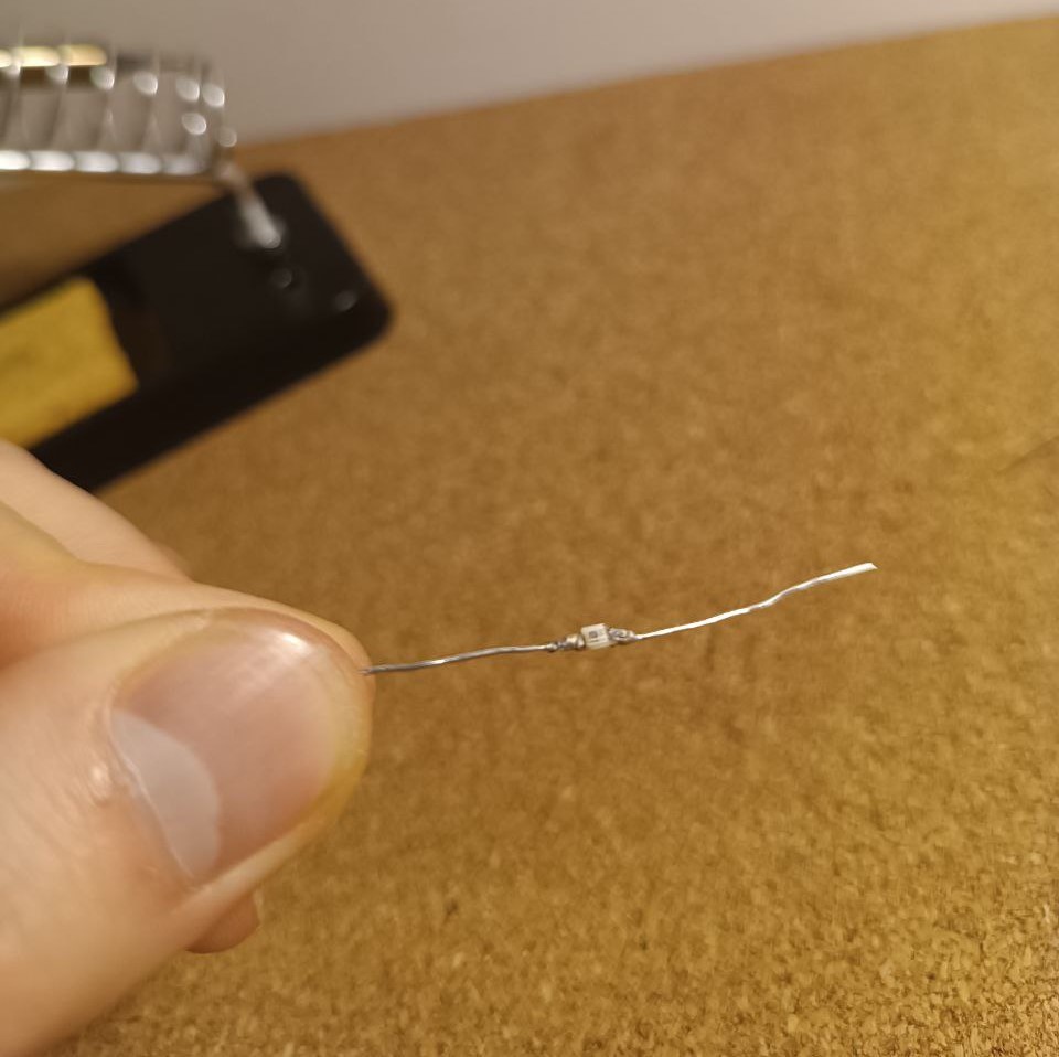
- For input decided to use phototransistor.
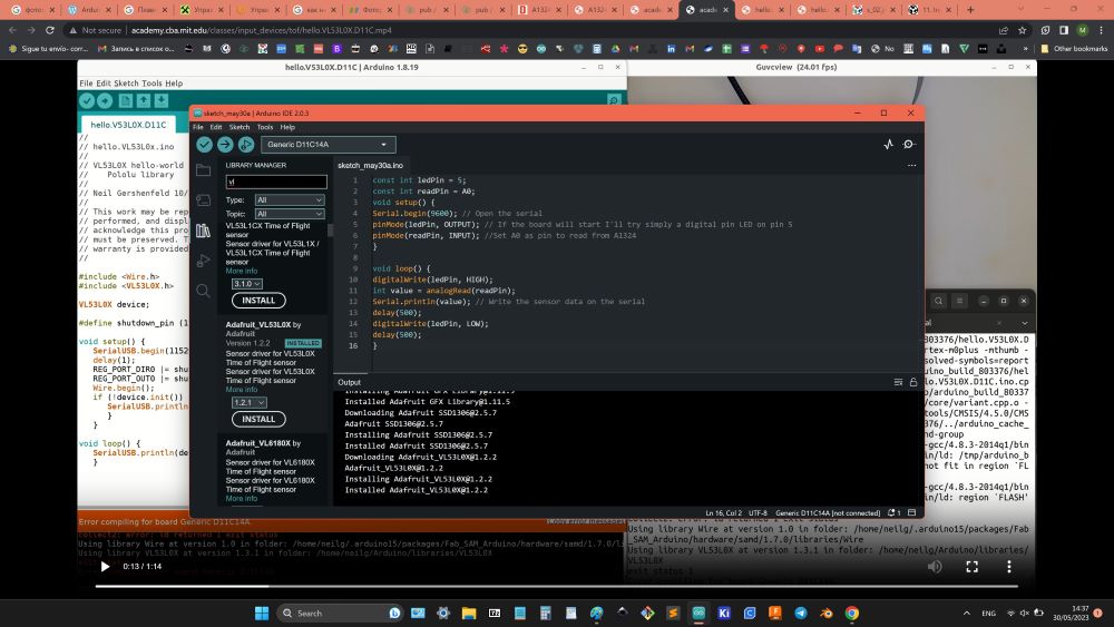
- Coded interaction between phototransistor and LED , to change level of LED glow depending on environment brightness.
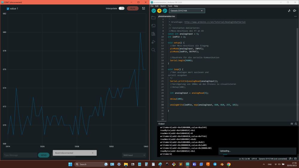
- It worked, but sensitivity was realy low (in range ~ 600-700, when real range 0 -1023).
- Supposed that reason is resistor (based on its value, changing value of photosensor defined), so changed it from 10K ohms to 1K ohms, but it did not give result, values just decreased twice, but range stayed same small.
- Decided that problem is in phototransistor, so soldered another one, but result was the same.
- So, decided to try photoresistor, but it behaved same way.
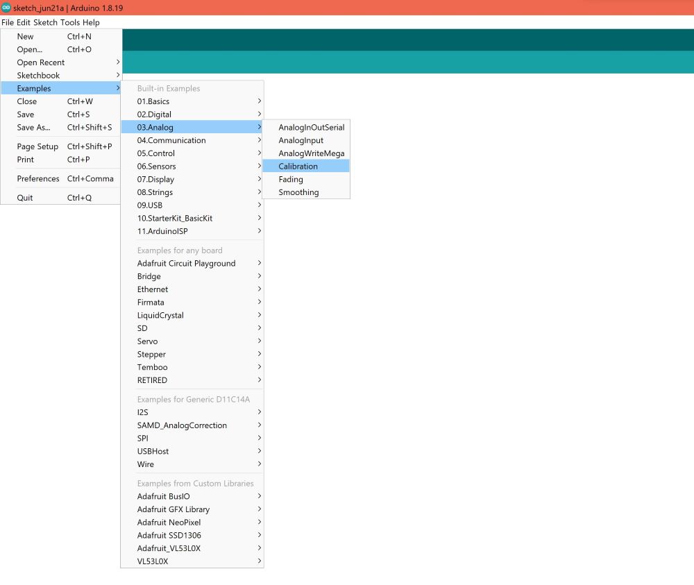
- Eventualy used example code from Arduino develope environment for analog sensors called "Calibration".
- That worked, sensor data became full range.
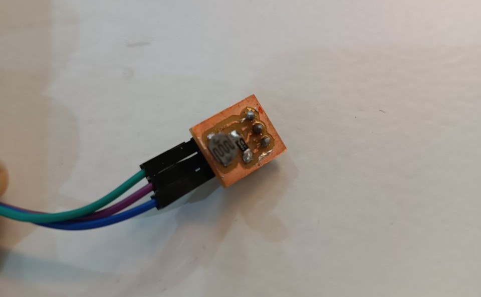
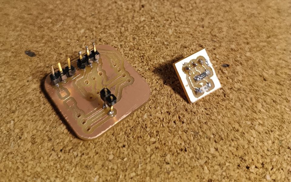
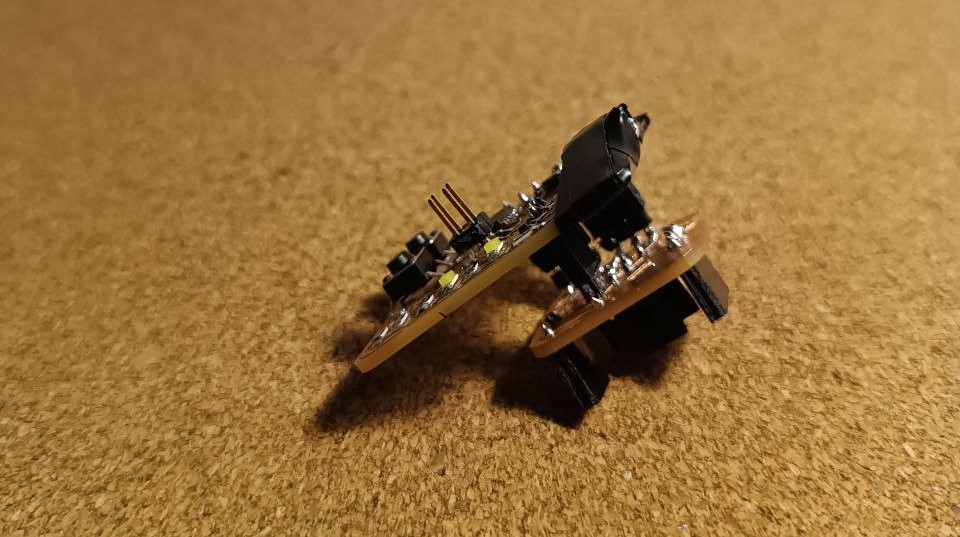
- This little board with sensor conected to additional board created for input and output devices and connected to first board created during electronic producing week, because made not enough pins.
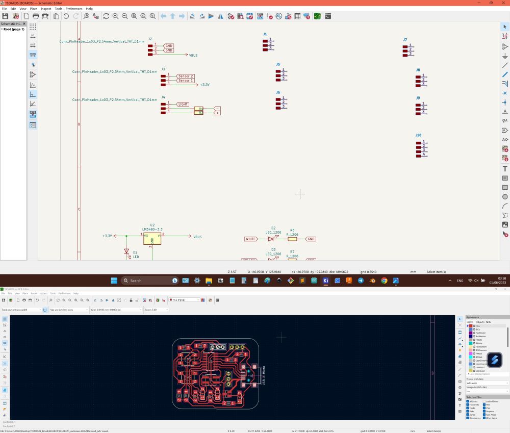
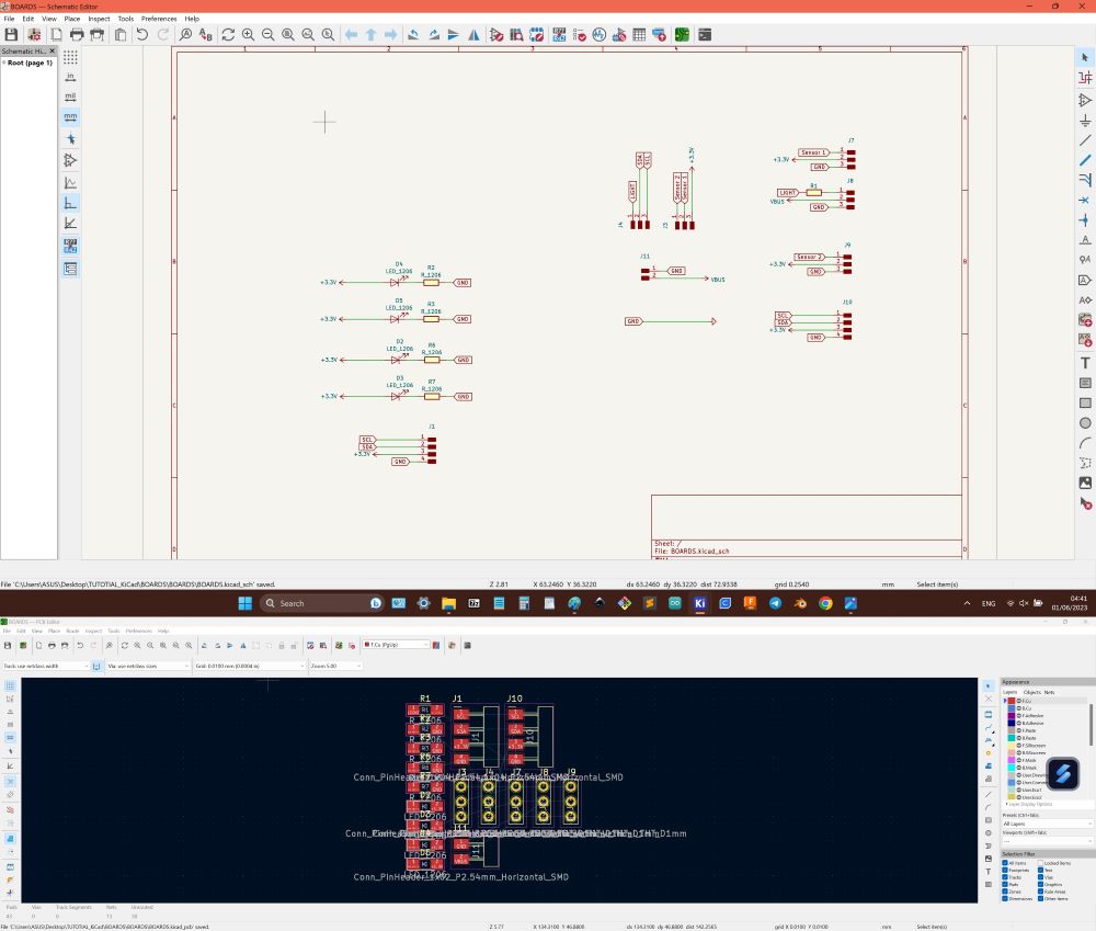
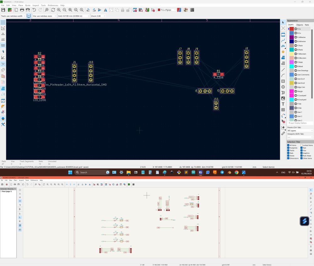
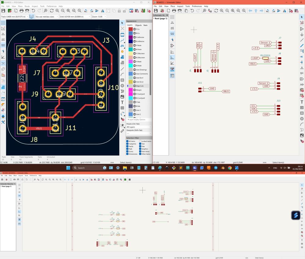
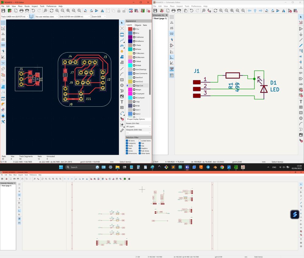
- Used Kicad, exported pins from first board, to make them adjustable, fork to enough amount of pins and grouped together pins for each device.
