3. Computer controlled machining
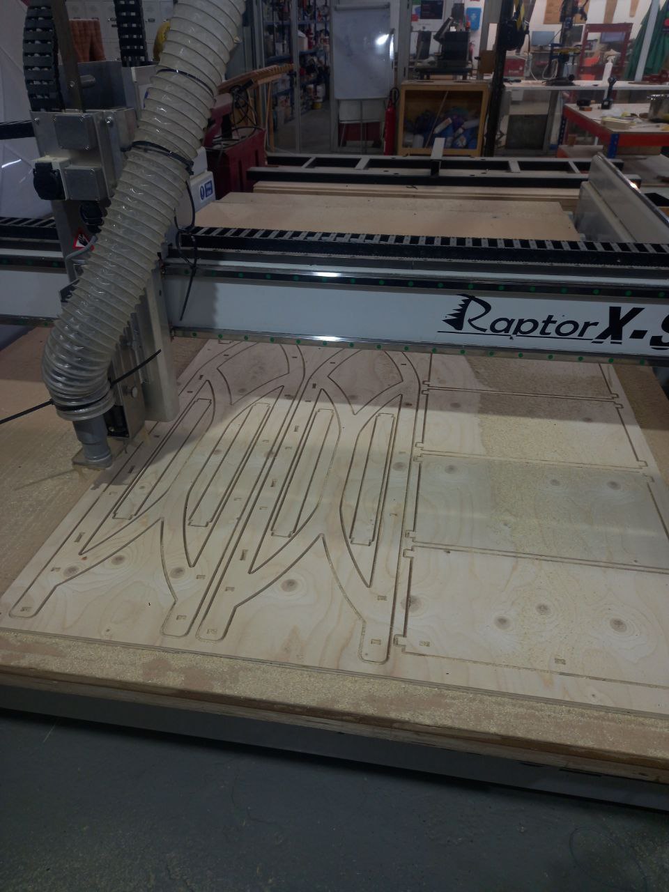
This week we used CNC milling machine to cut something big from plywood. Cut CNC test together.
Documentation
Creation
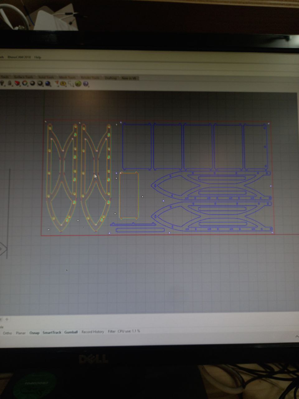
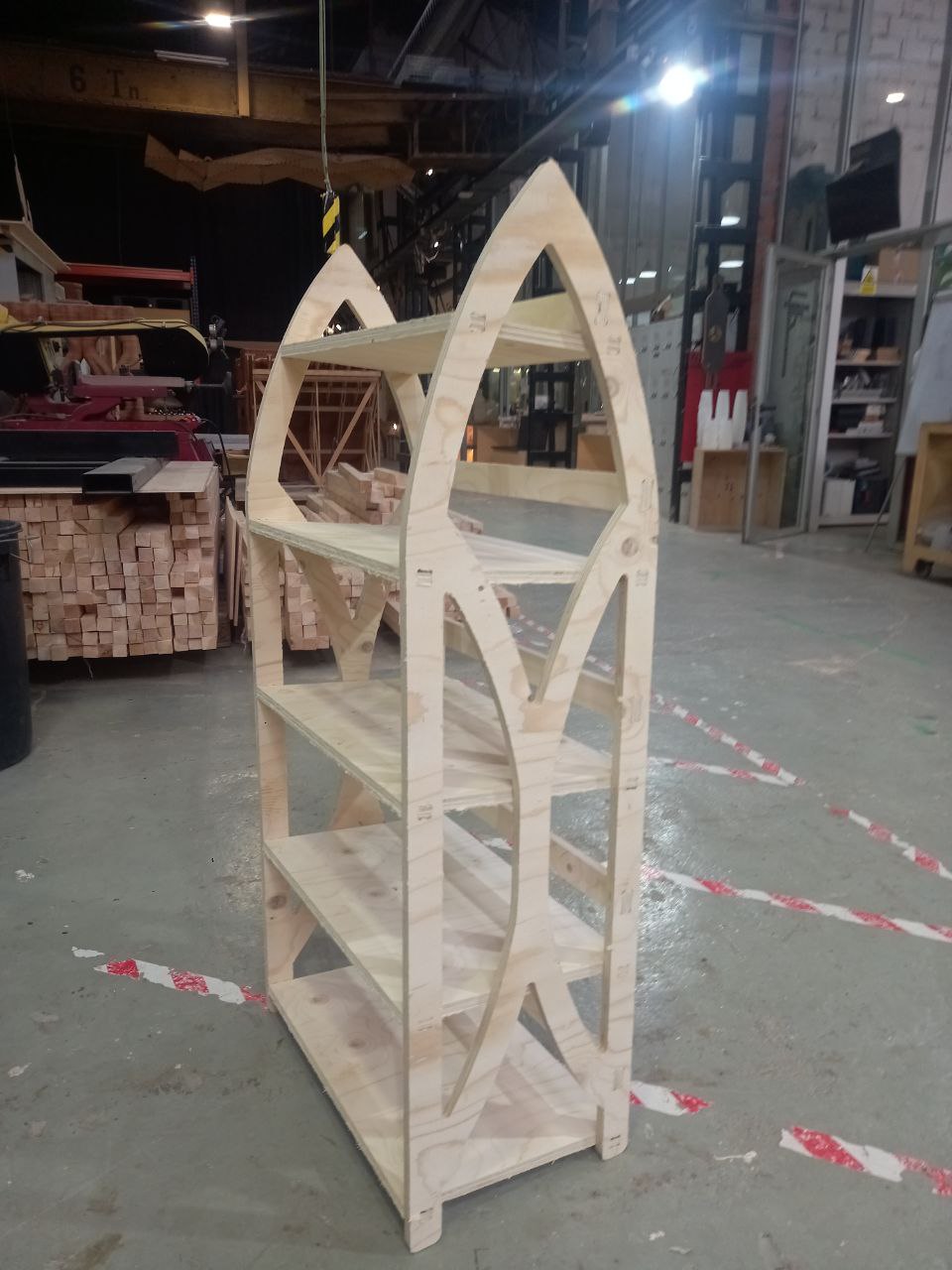
- Designed using Rhinocerous, inspired by gothic arc.
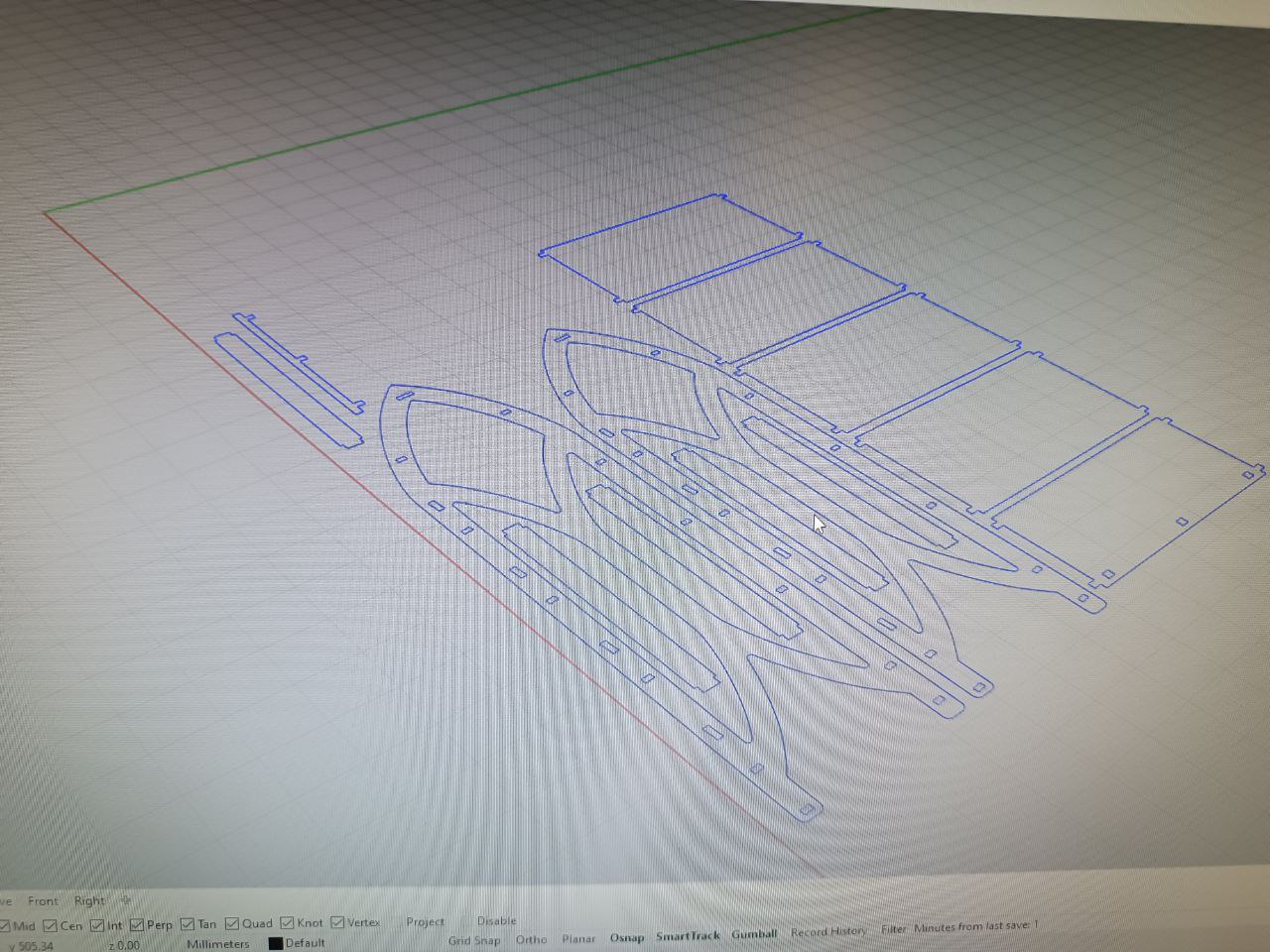
- Used usual Rhino commands: polyline, fillet edge, extrude, move, 1D scele and so on.
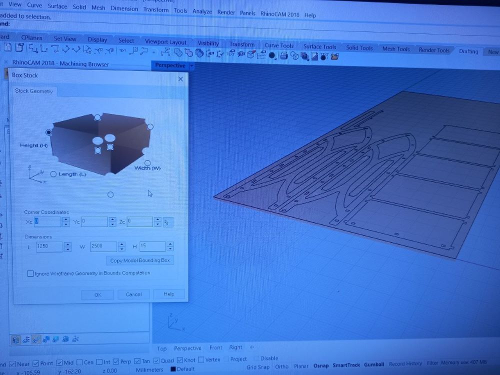
- Set matetrial sizes and Z-axis origin referring to material.
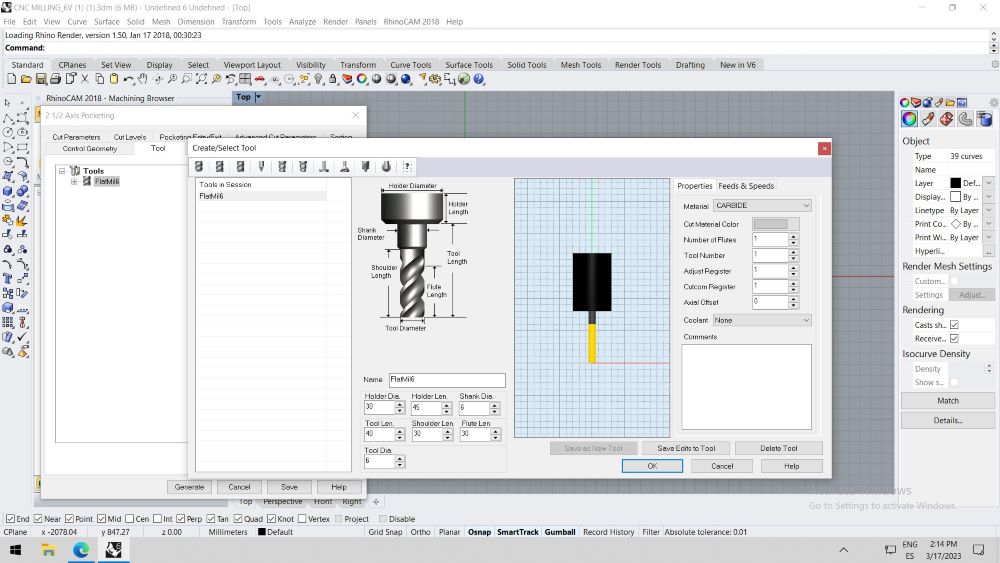
- Setting tab for 6mm diametre flat tool (for plywood using down cutting milling cutter).
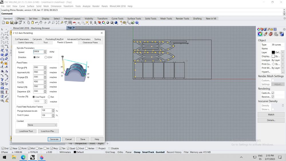
- Pocketing of joint holes, setting speeds.
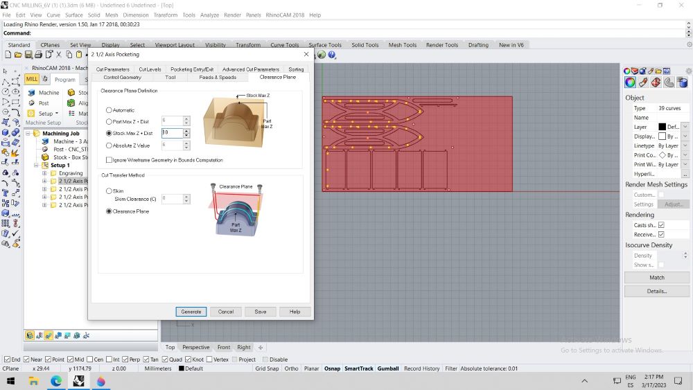
- Pocketing safe plane setting tab.
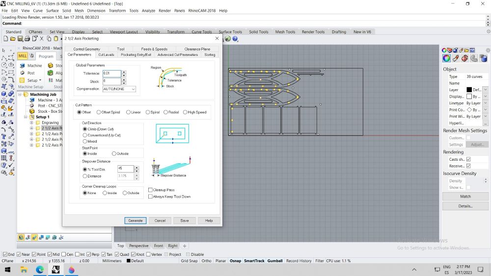
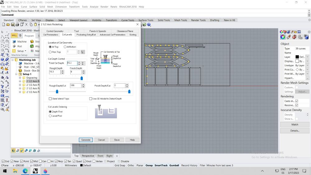
- Pocketing cuts preferences and depths.
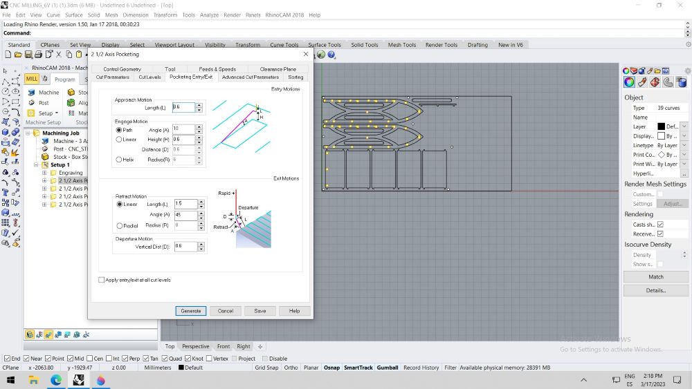
- Pocketing preferences of entering and exiting material.
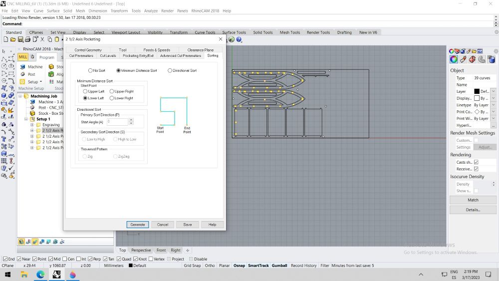
- Set minimum distance tool optimisation.
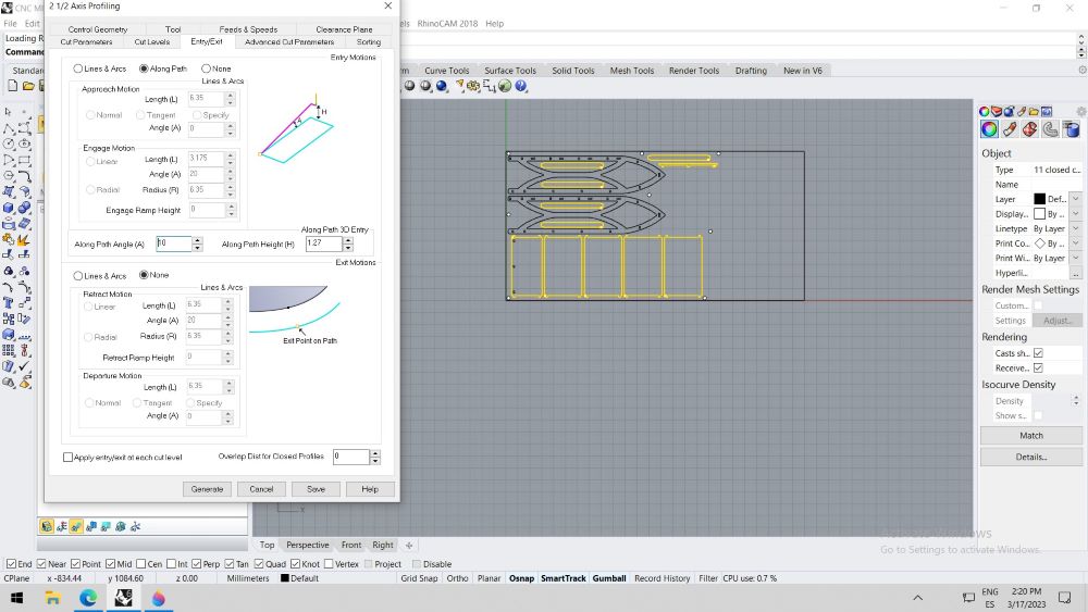
- Axis Profiling Exit / Entry settings have to be Along Path to not destract exterior material.
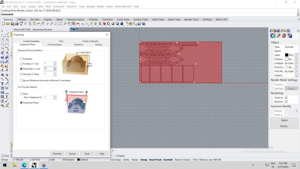
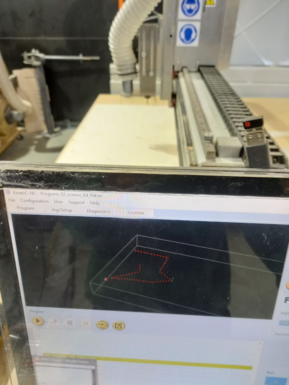
- For Engraving (screws pointing) safe plane should be twice higher, because when material not screwd, it is more curved.
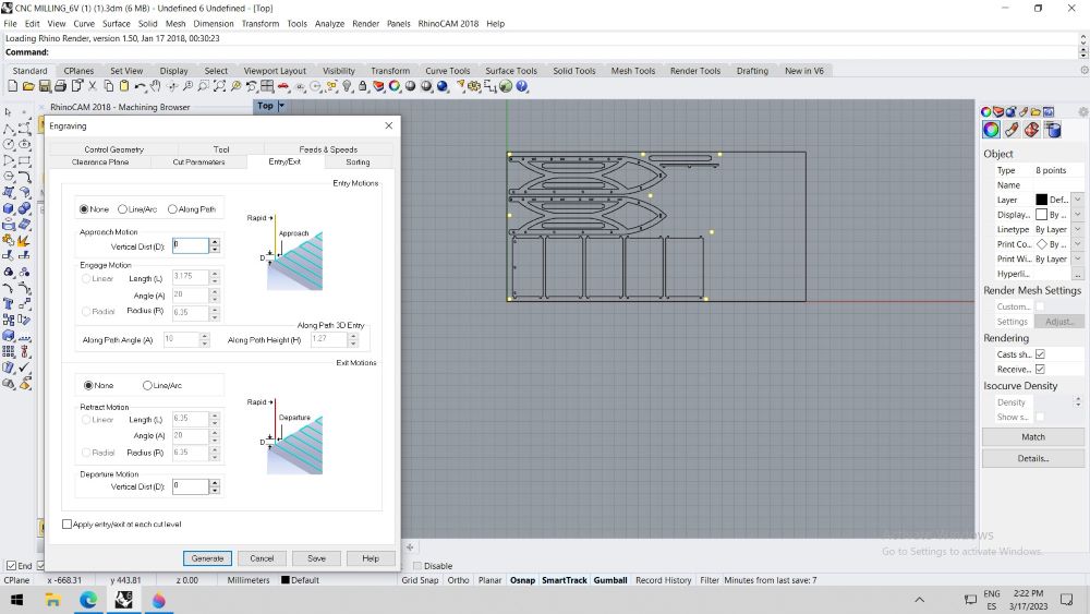
- For Engraving Exit \ Entry settings shouldnt be defined, to make only Z-axis movement.
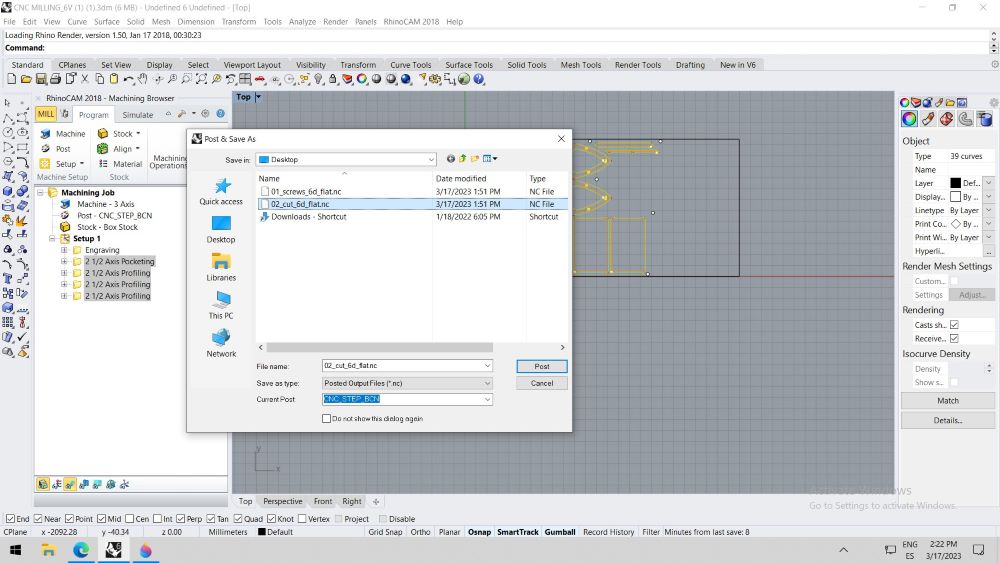
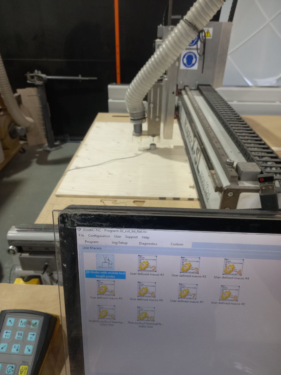
- To make algorithm for CNC need to Post slected cutting trajectories in correct order.
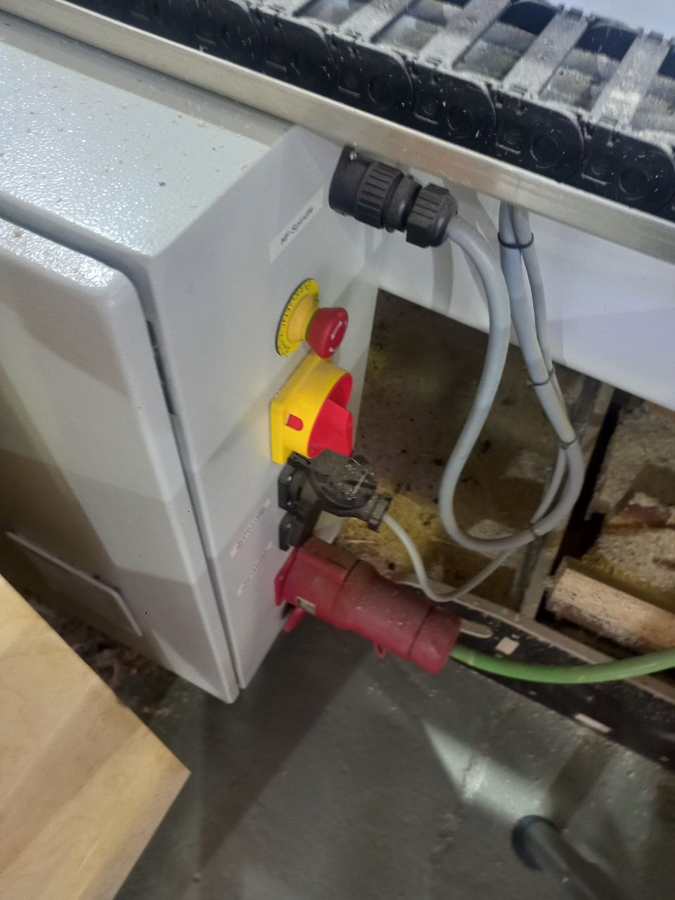
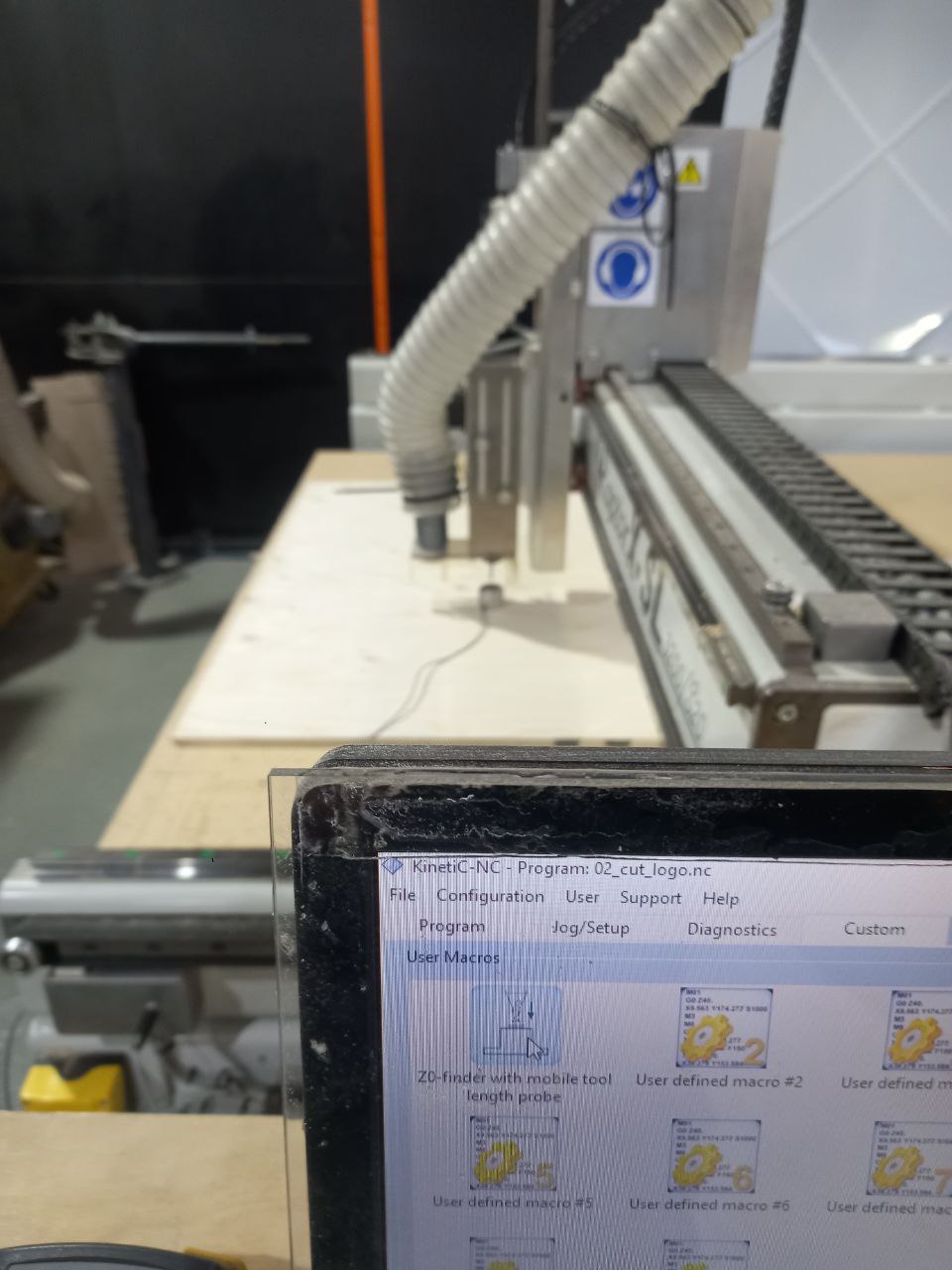
- Machine ON by turning switcher.
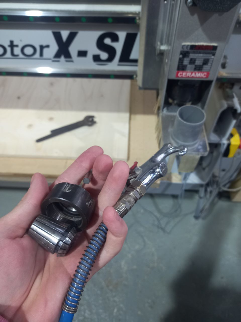
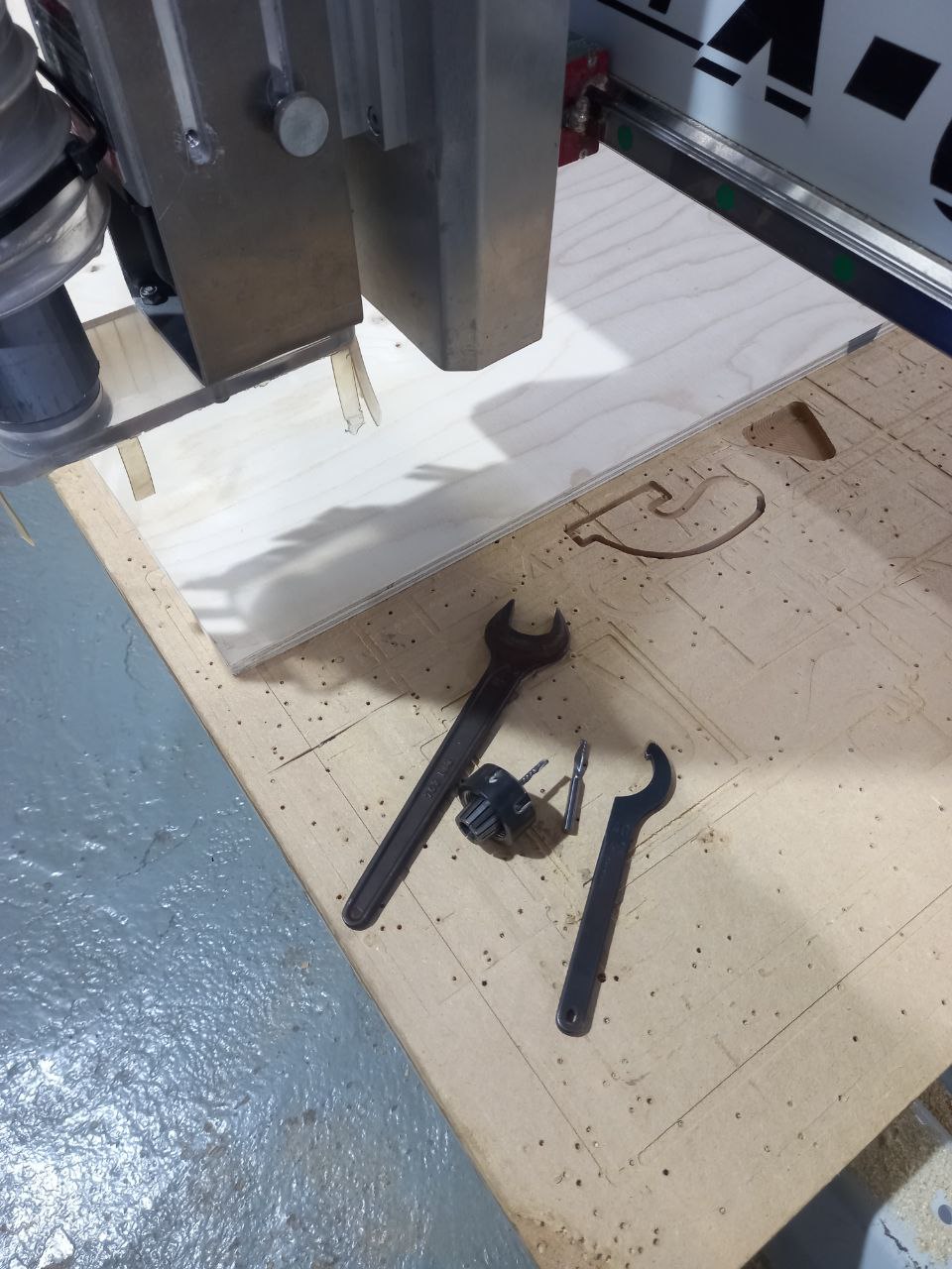
- Changed tool and clened collet.
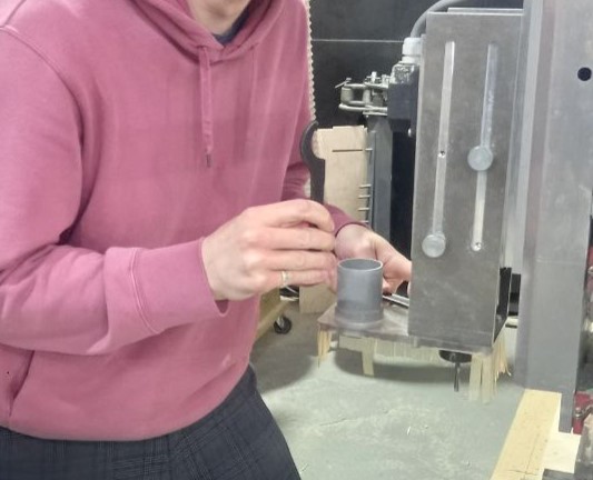
- Placed material, put collibration button on material.
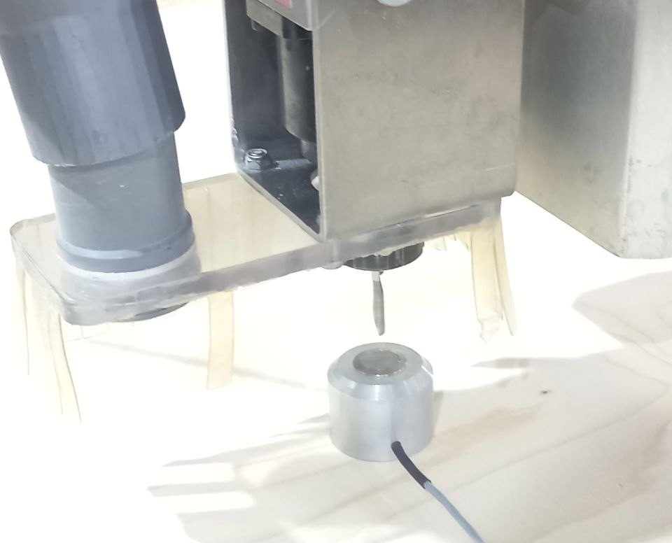
- Started programme for screws, screwed.
- After collibrated Z-axis again (screwed material more plane).
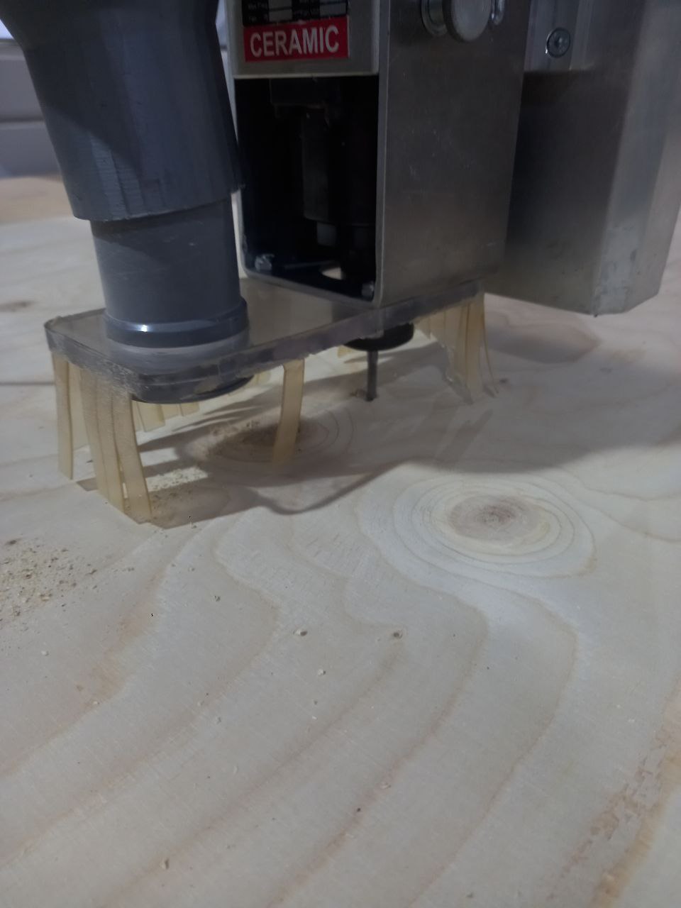
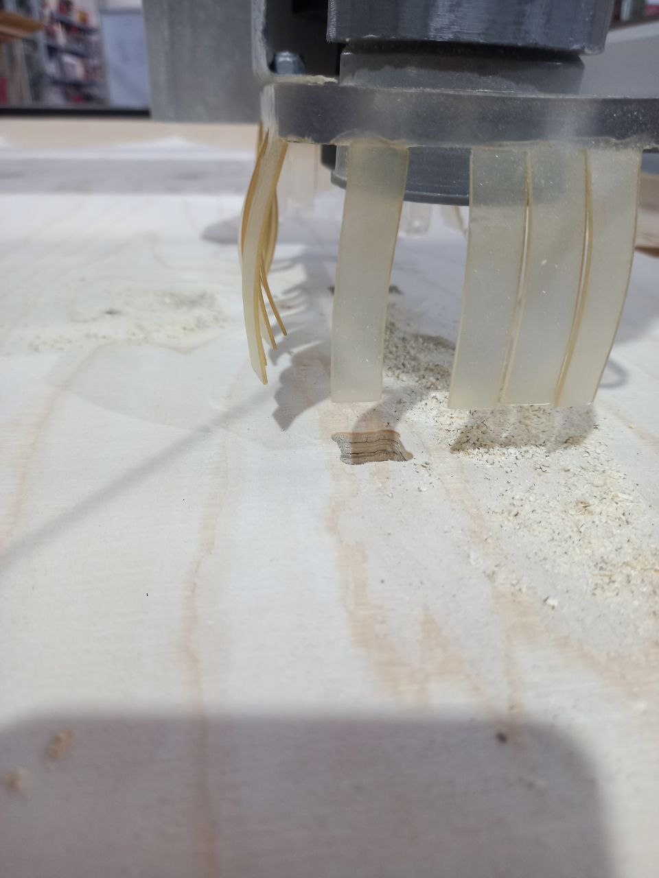
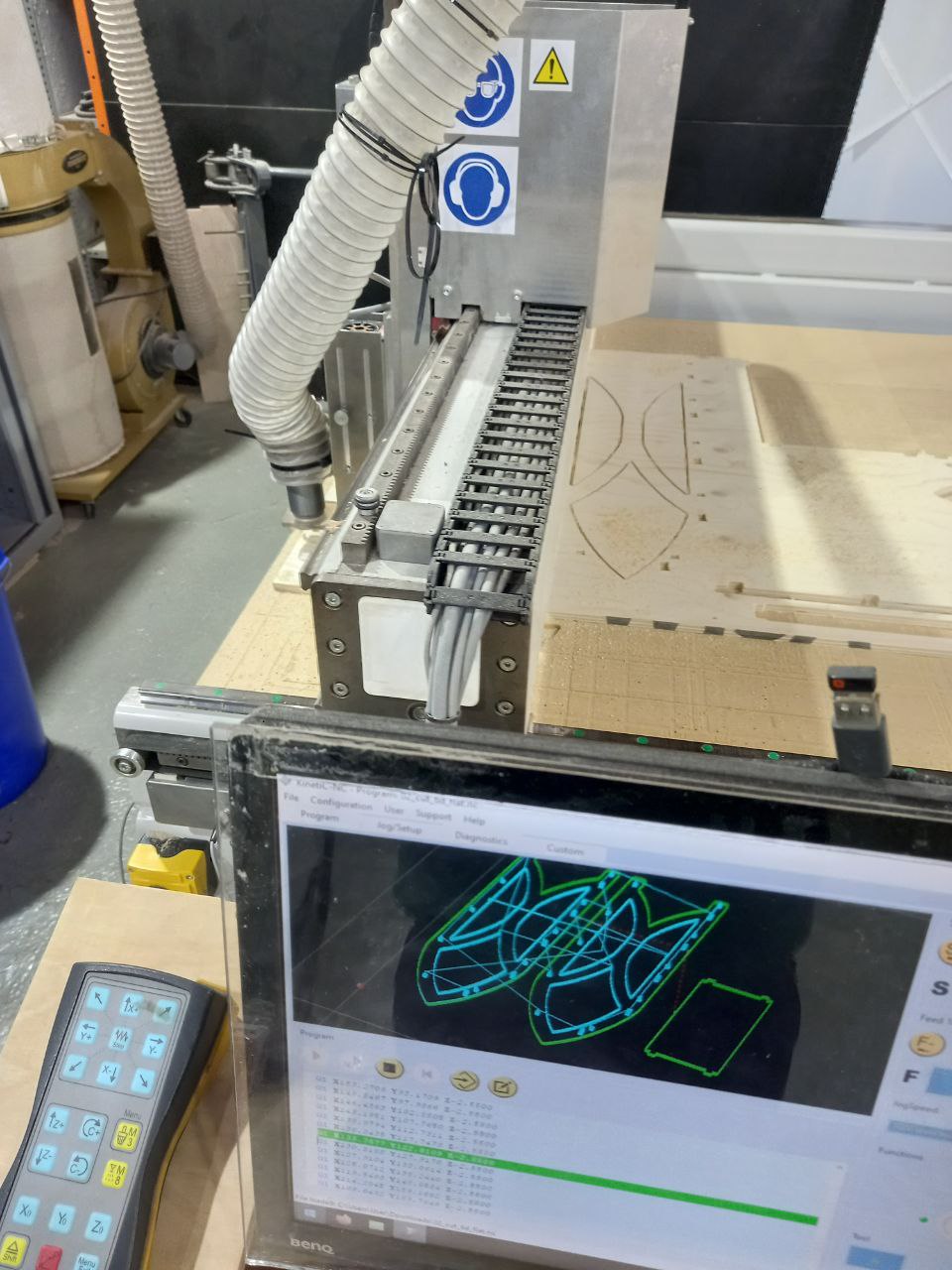
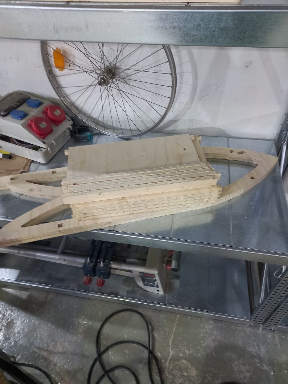
- Started to cut
- Bridges done well.
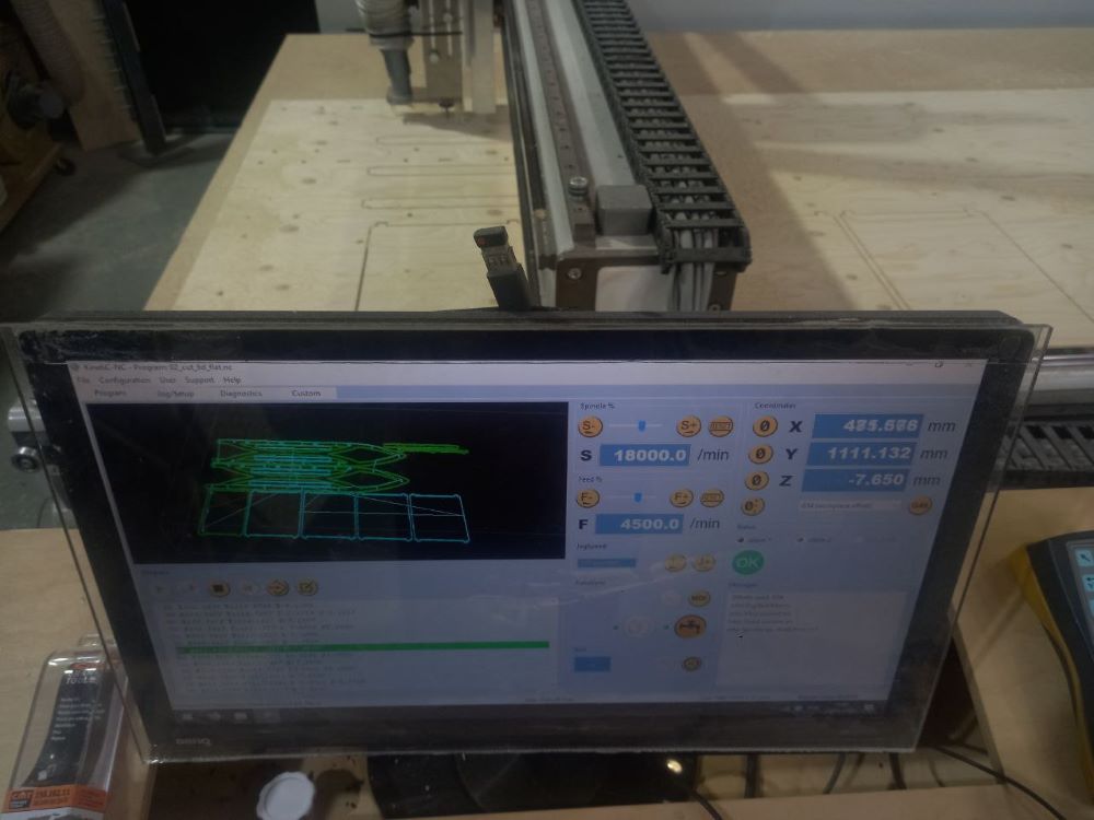
- Simulation corresponds to cutting process and looks good)
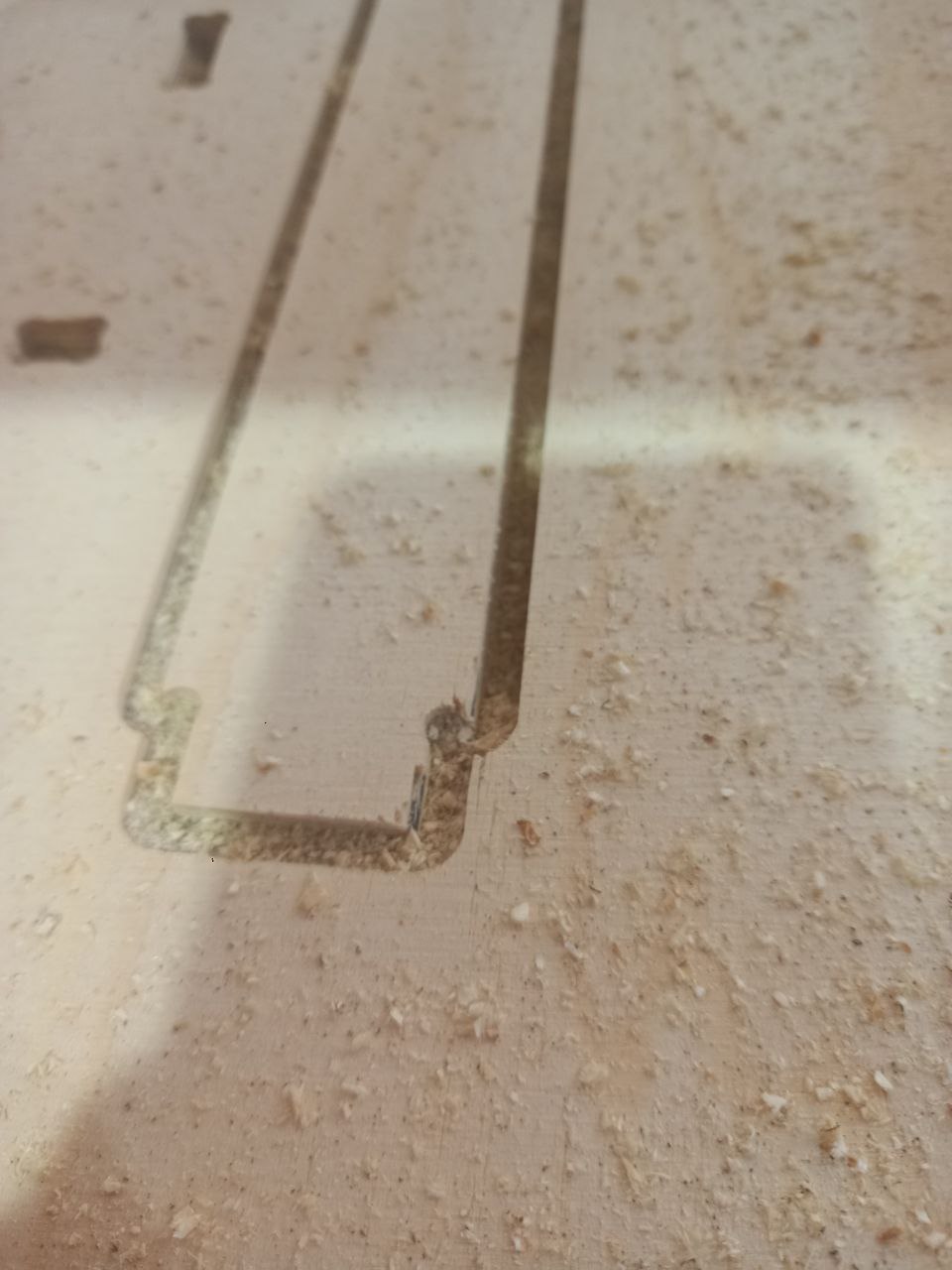
- This plywood quite soft,easily cleaves.
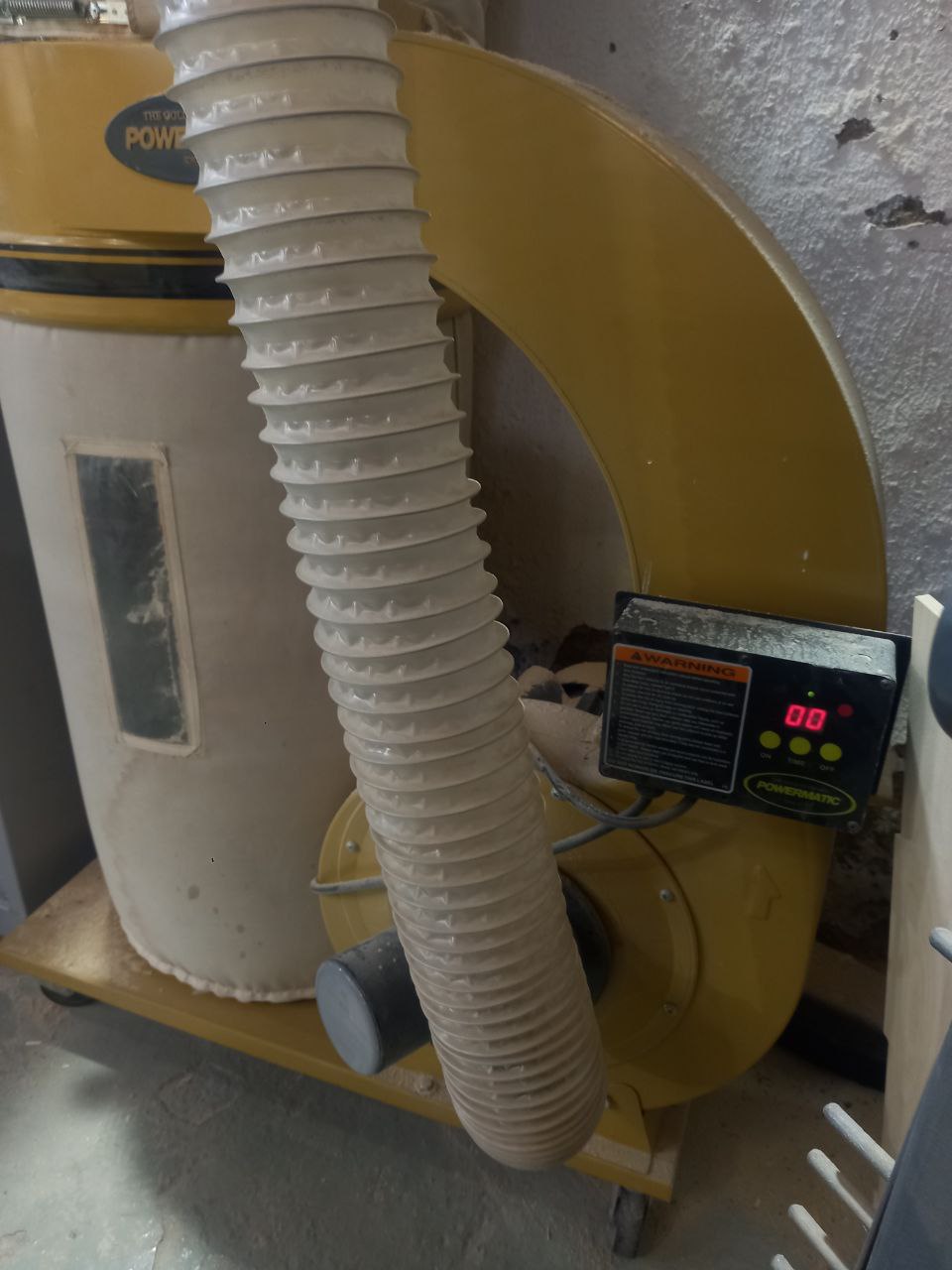
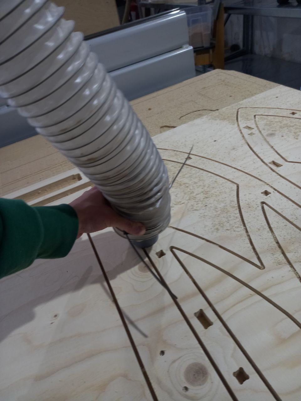
- Air pump ON.
- Mostly done.
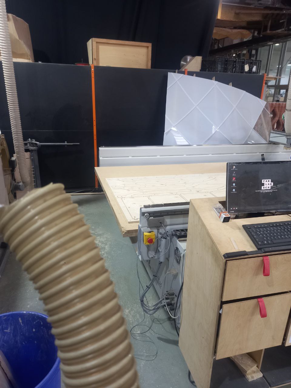
- Tried to pump by vacuum cleaner, after used air pump.
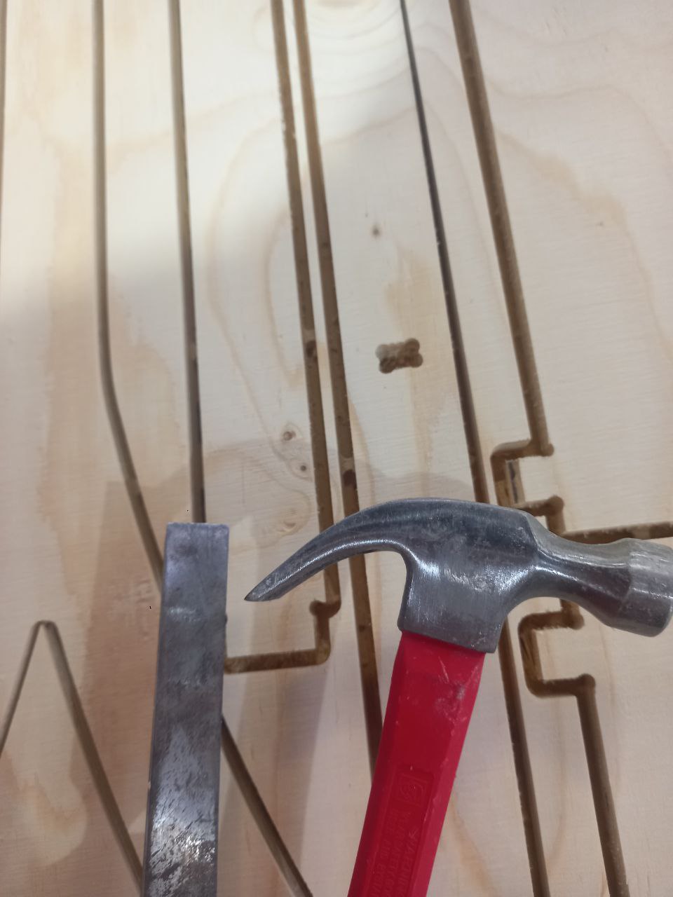
- Used chisel and hummer to break bridges.
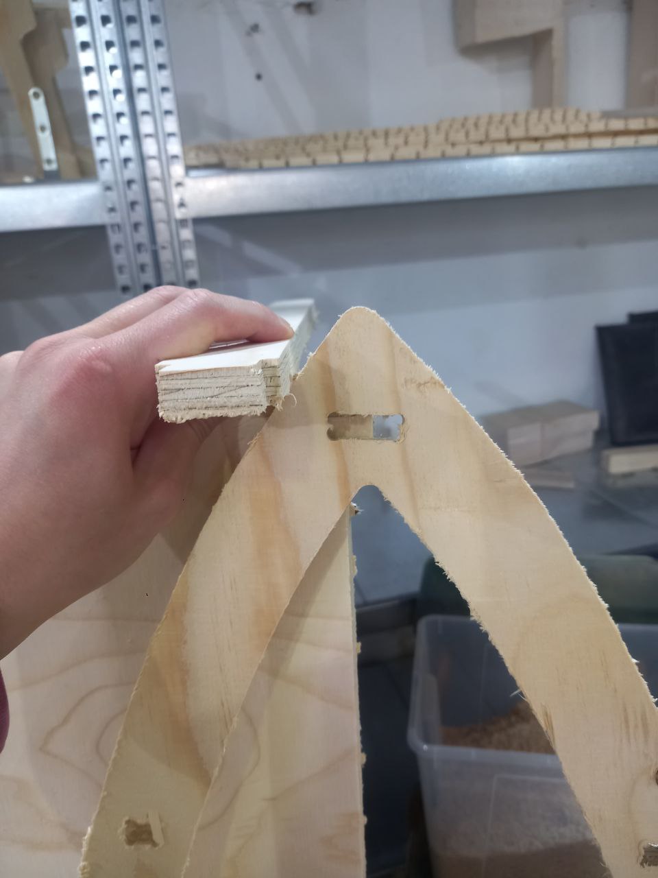
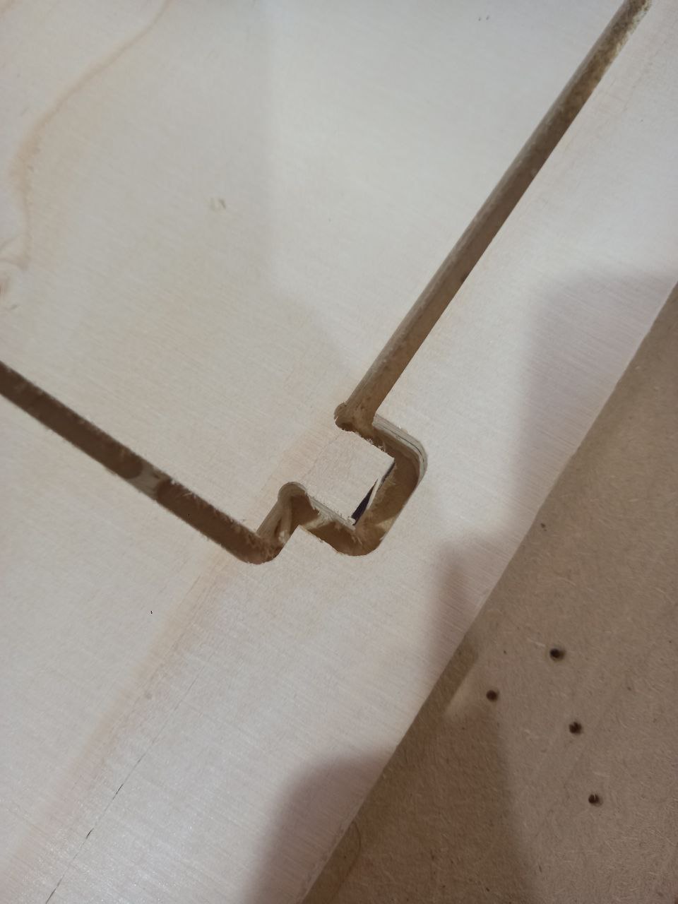
- Material was 15 mm, not 10 as I thought, so joints holes were not correct.
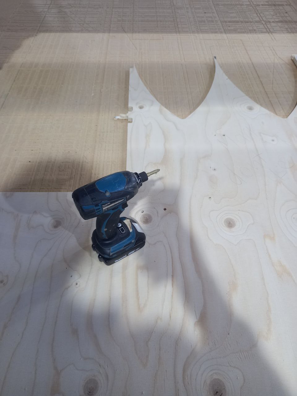
- Next day I changed sizes of holes and height of shelf ot arrange it on least material piece.
- Changed tool.
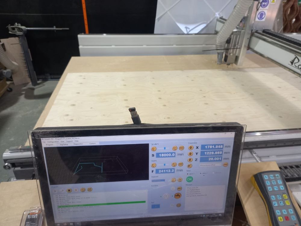
- Collibrated X, Y and after Z-axis Origin position.
- Checked that coose correct file on screen.

- Screwed.
- Recollibrated Z-axis.
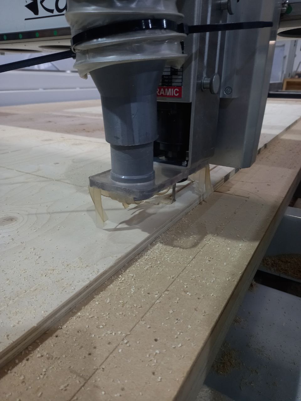
- Started to mill now holes have correct size, depth defined well.
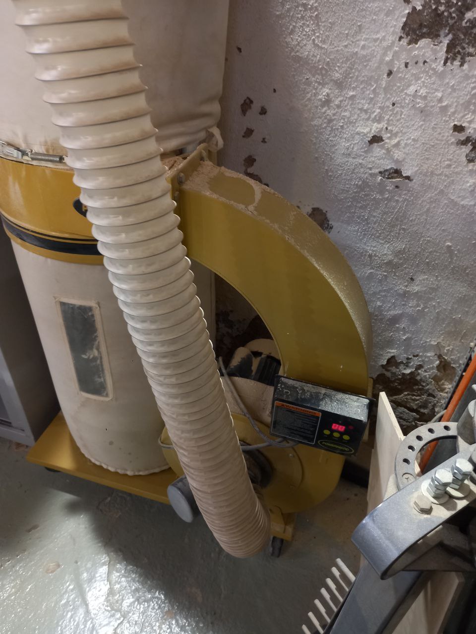
- Remembered that need to switch on pump.
- Prosessing...
- Mostly done.
- Unscrewed.
- Vacuumed major part of chips.
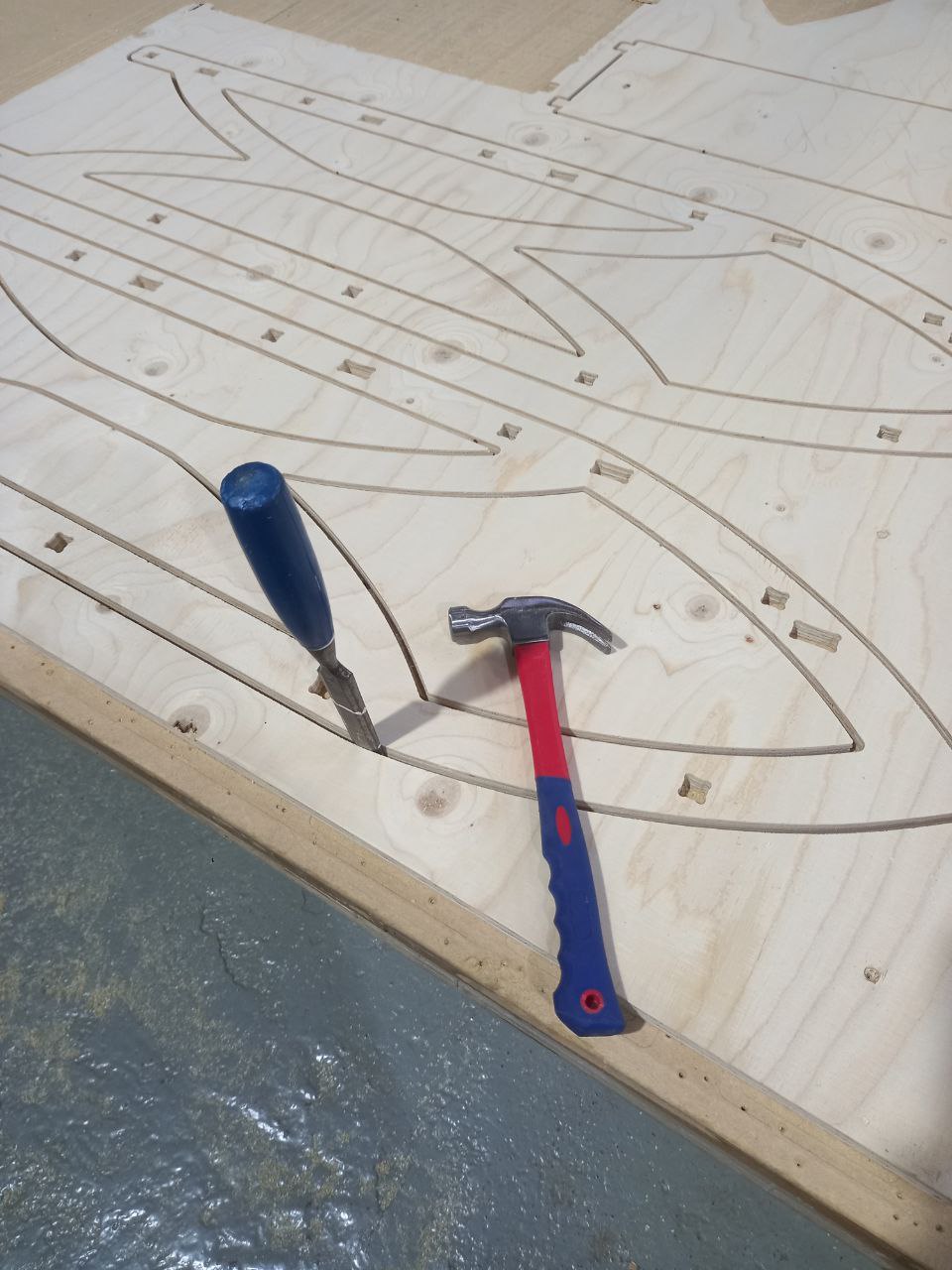
- Cutted bridges by hummer and chisle.
- Now cutted well.
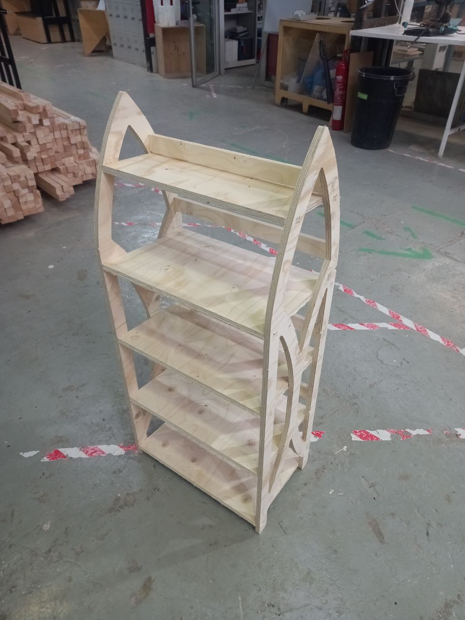
- Done. Actually milled not perfect, plywood too soft, chip off because of that.