8. Electronics production
This week we used Roland (mini-CNC) to mil electronic boards, for further soldering, programming and coding.
Documentation
Board cut
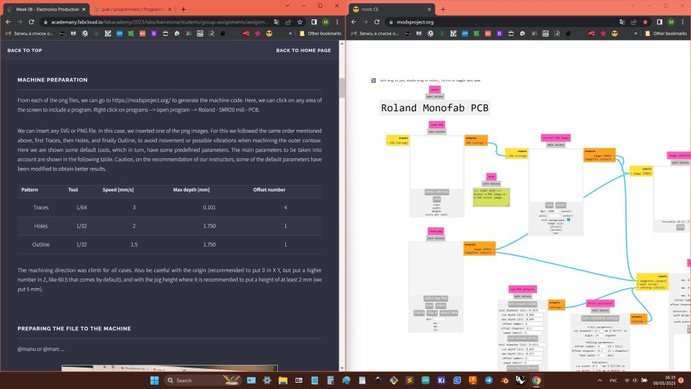
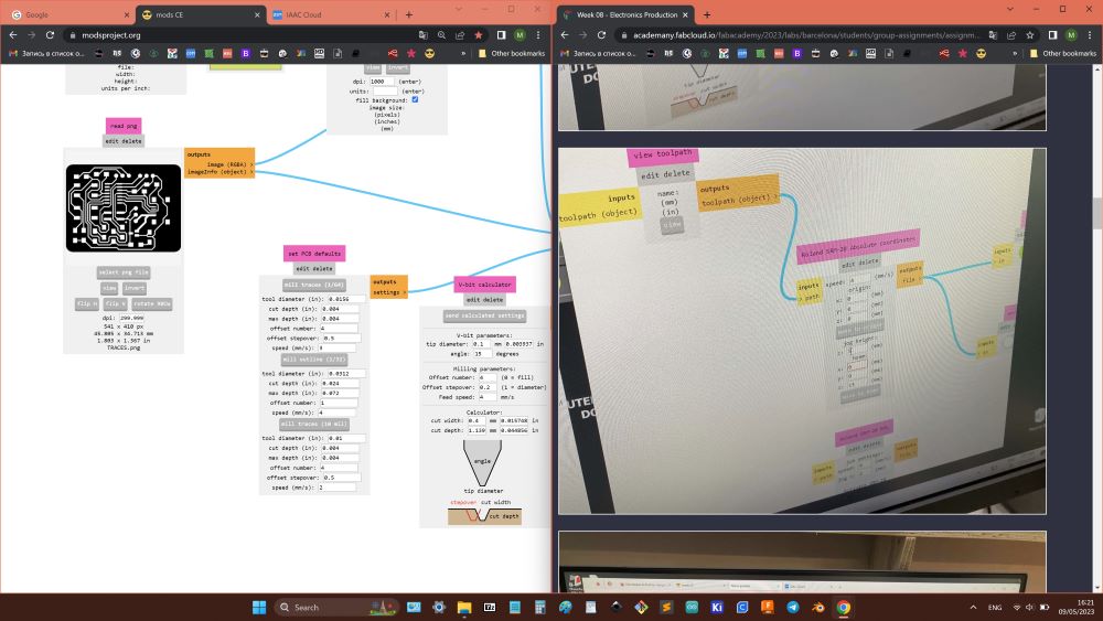
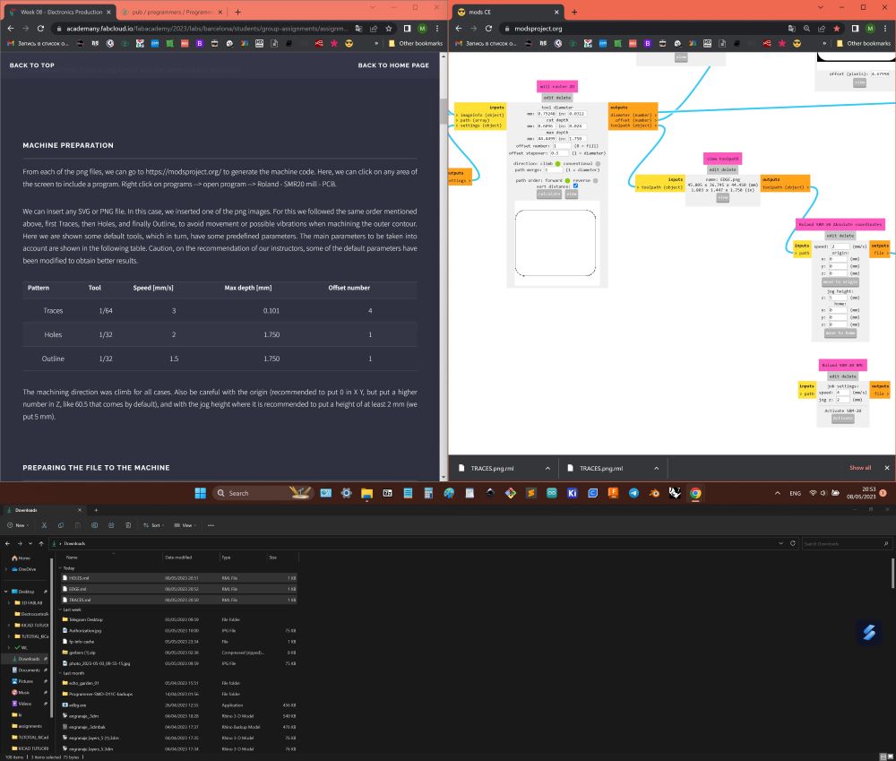
- So, for board production Roland machine was used and adjusted.
- Used nodes to create gcode files.
- Referenced to group assignment test for more acurate settings.
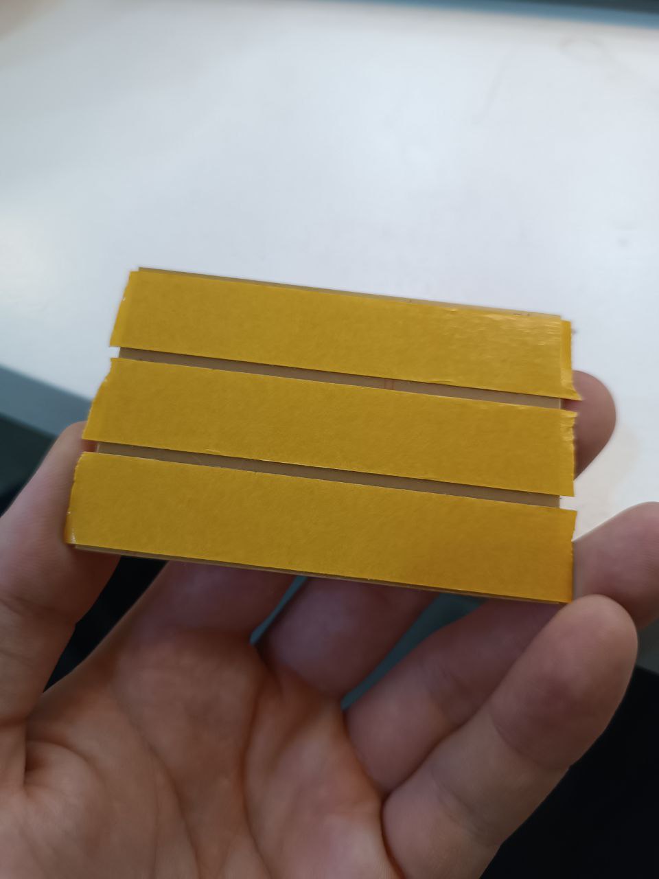
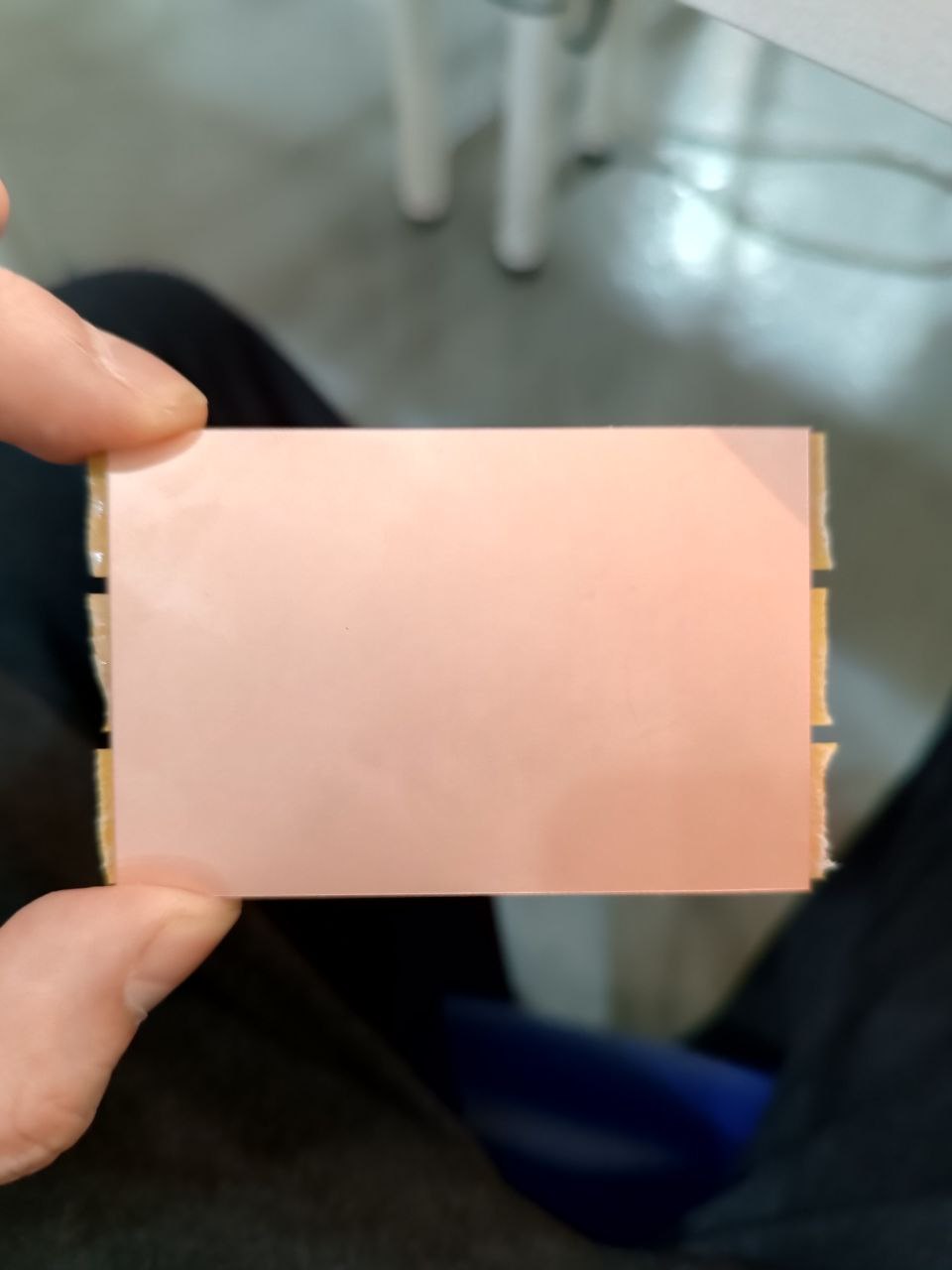
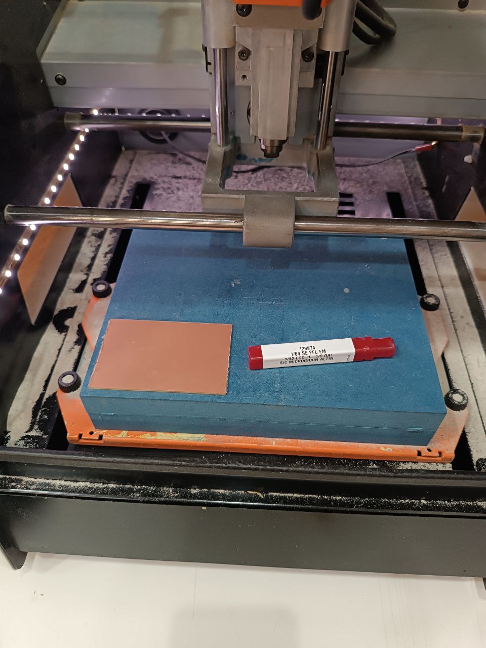
- Board with copper layer have to be placed plane (that is why machine frame is massive despite size), so ends of tape need to be not below bottom surface to be more plane.
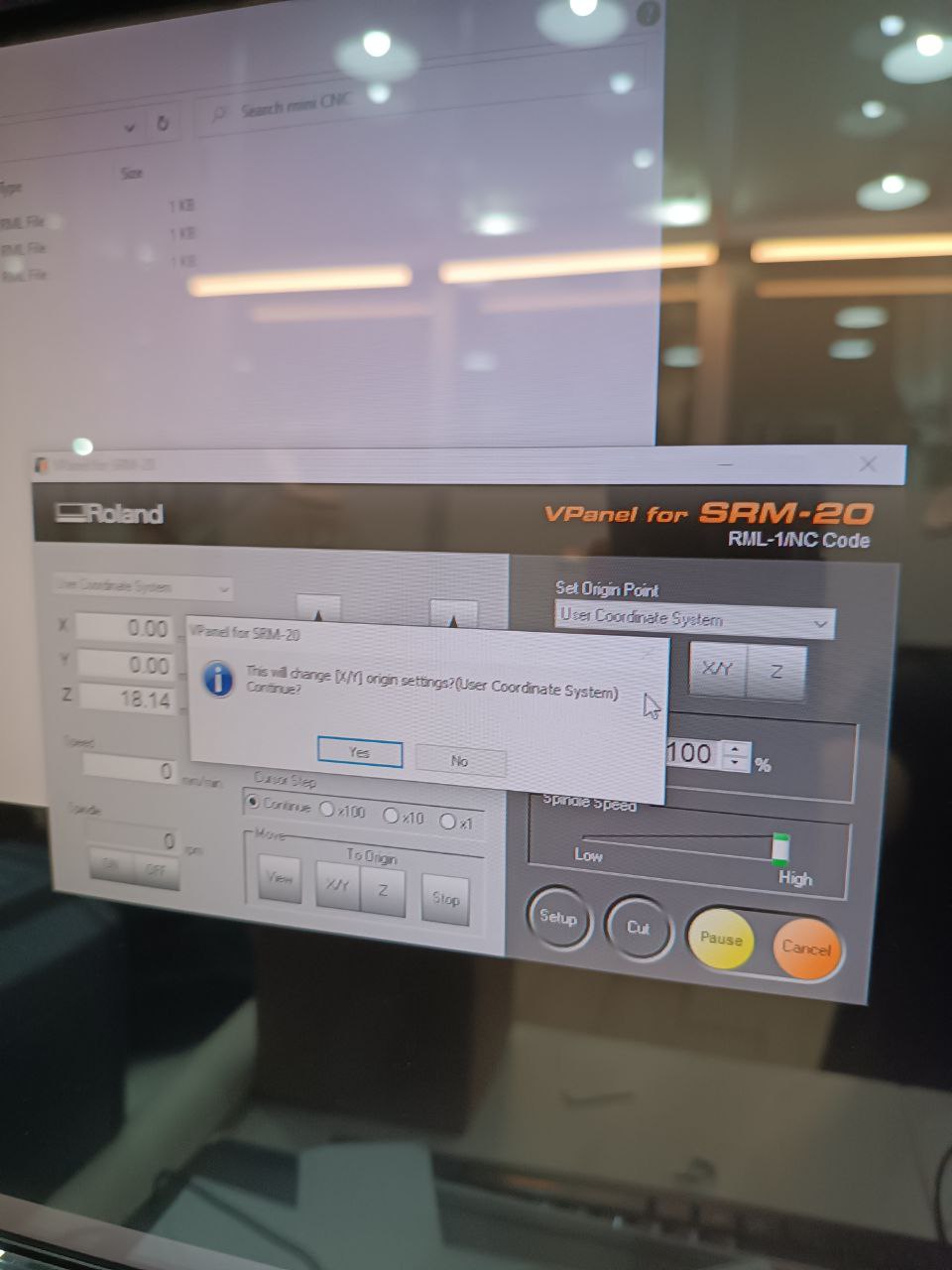
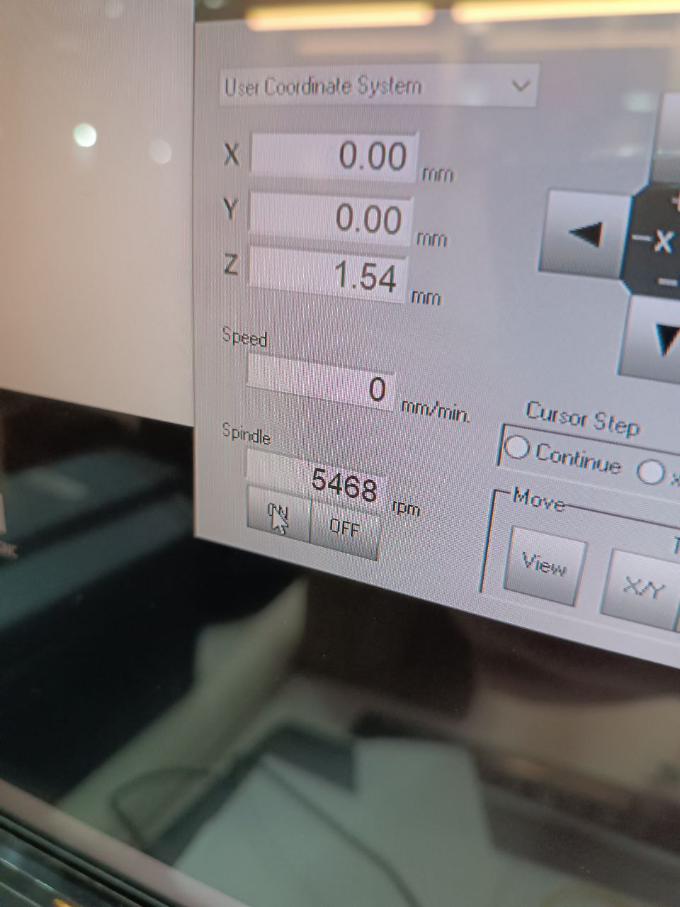
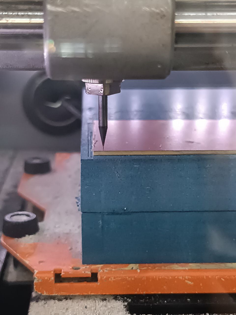
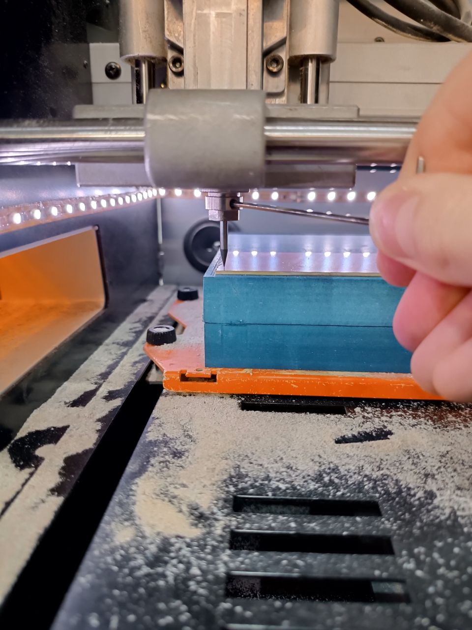
- Machine moves XY only closed.
- First home, changed XY origin.
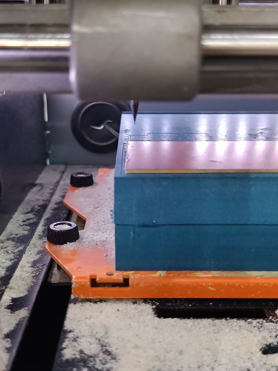
- Moved mil down close to surface (need to be careful, very easy to break mil 1/64 inch for traces and 1/32 inch for holes and cut out).
- Untighten mil, carefully contacted it with surface and reset Z, after still untighten pushed up on 0.03 mm and tight follow up mil and surface contact.
- Another way is when mil close to surface, spin it and with 0.10 - 0.01 mm steps touch surfase to create little dust of plastic under copper.
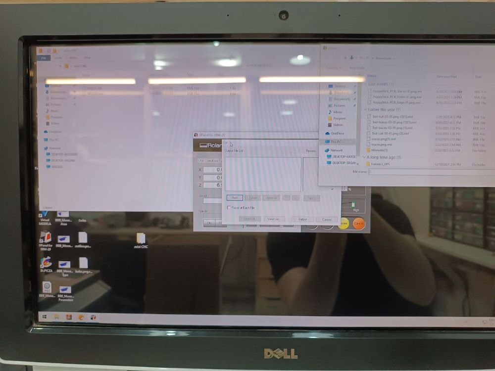
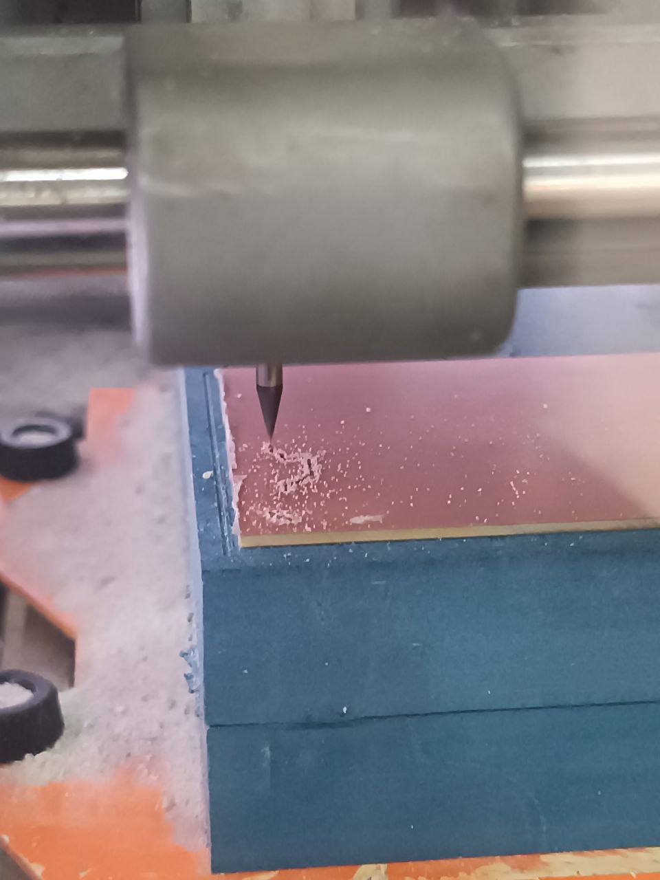
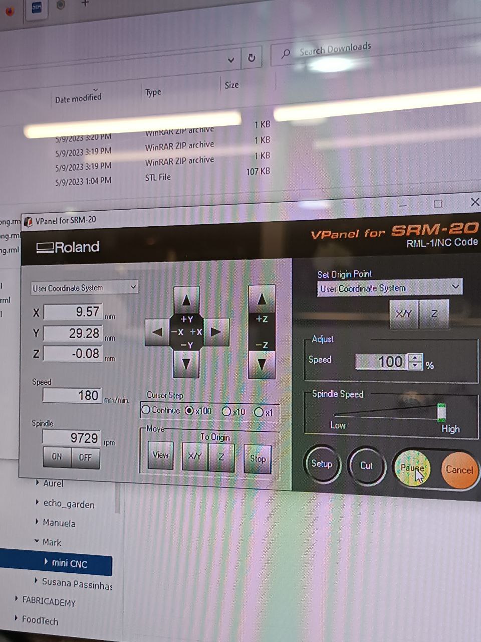
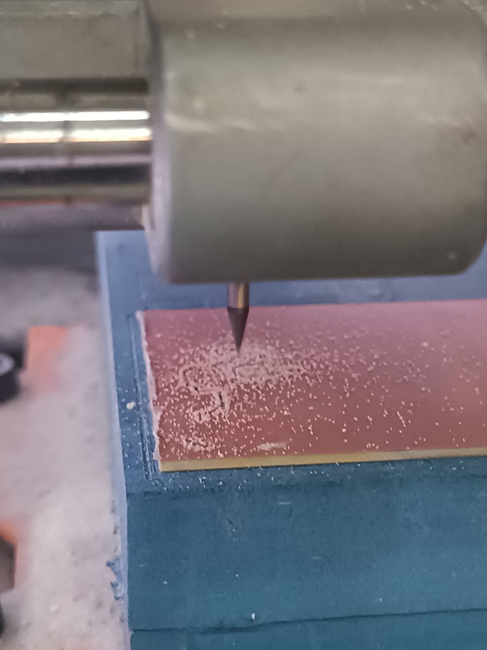
- Press CUT in soft, choose file to cut. pressed OUTPUT, cut started, was ready to stop machine if would see that sometjing go wrong. But there was enough dust and I thought that it ok.
- As defined I made misstake with SVG files sizes, hence export, hence mismatching of holes and final cut.
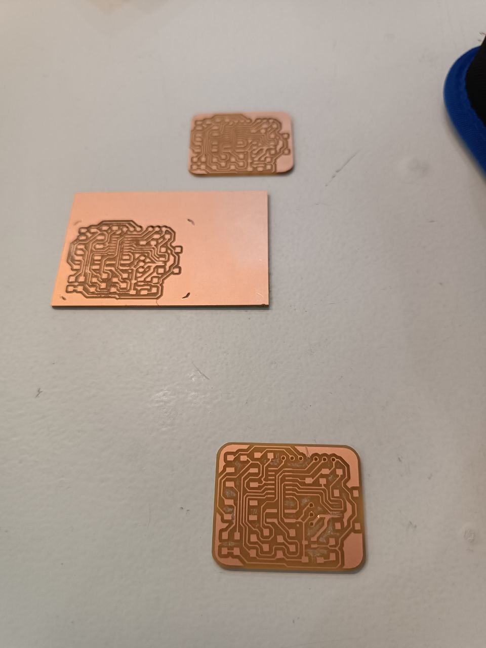
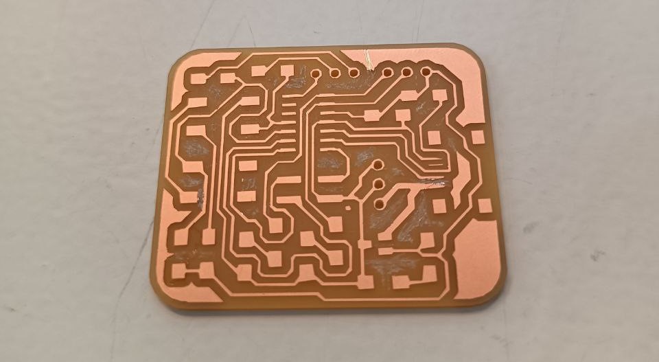
- Eventually on third try it cut well. Two points did not cut, fixed it with knife, except this, cut very crean.
Try soldering
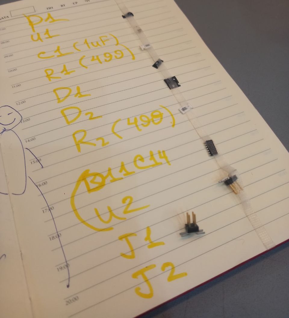
- Listed and collected all components.
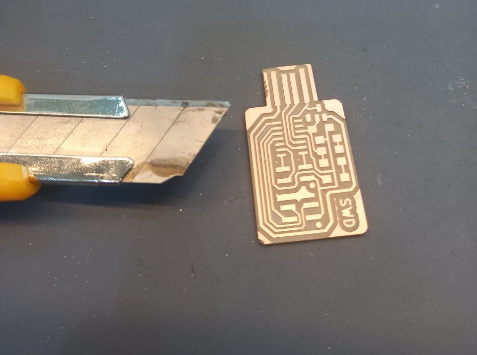
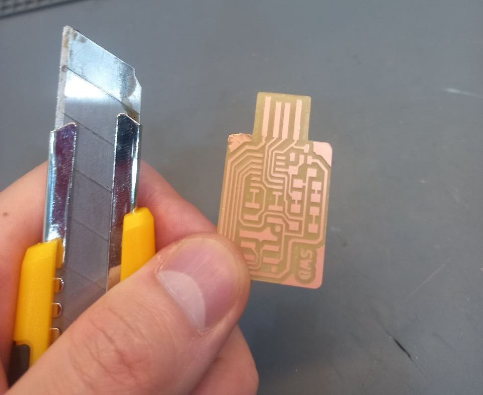
- First neded to clean up sides copper lines, to avoid short.
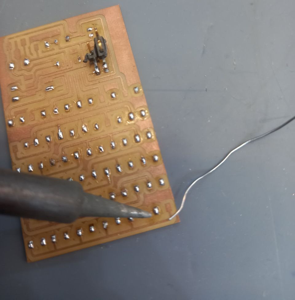
- Tried few times how solder melting and adjasting.
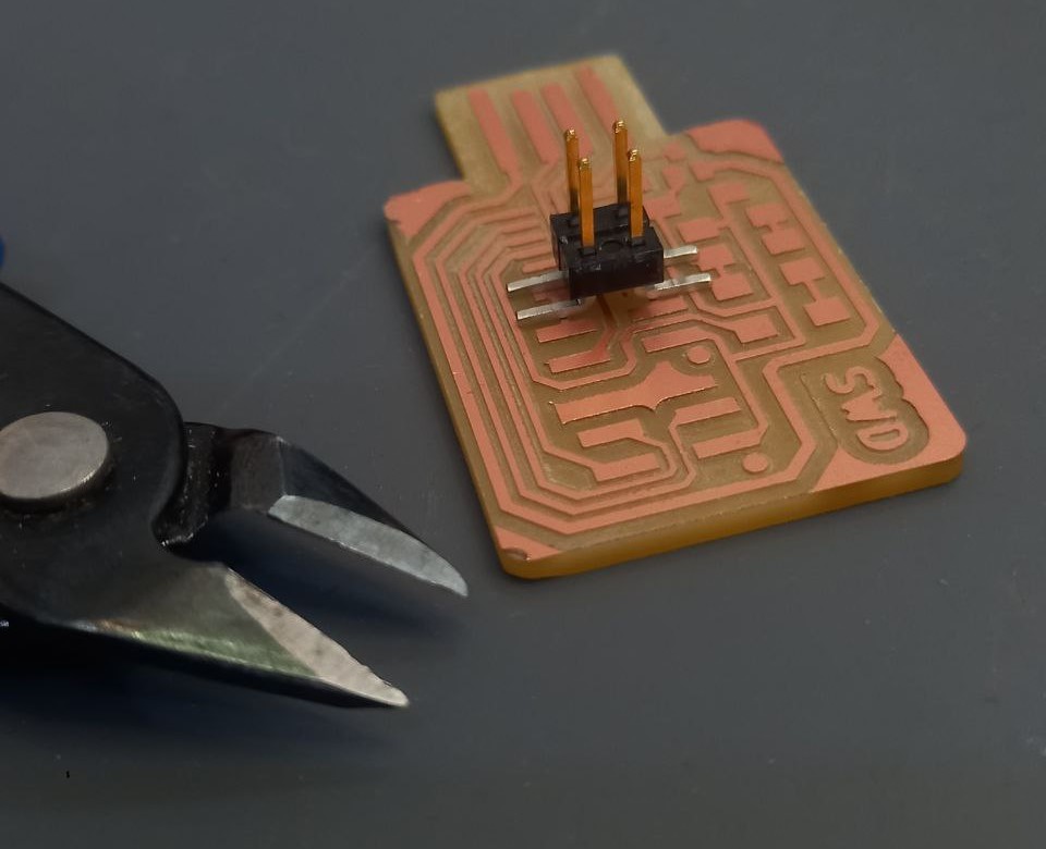
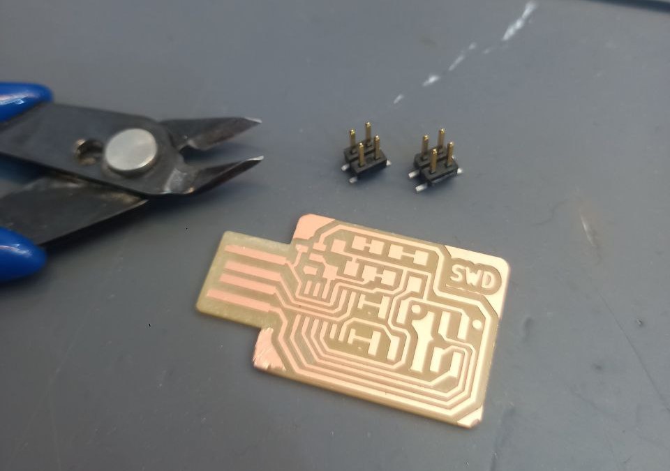
- 4-wire connector legs were too long, so shorted them.
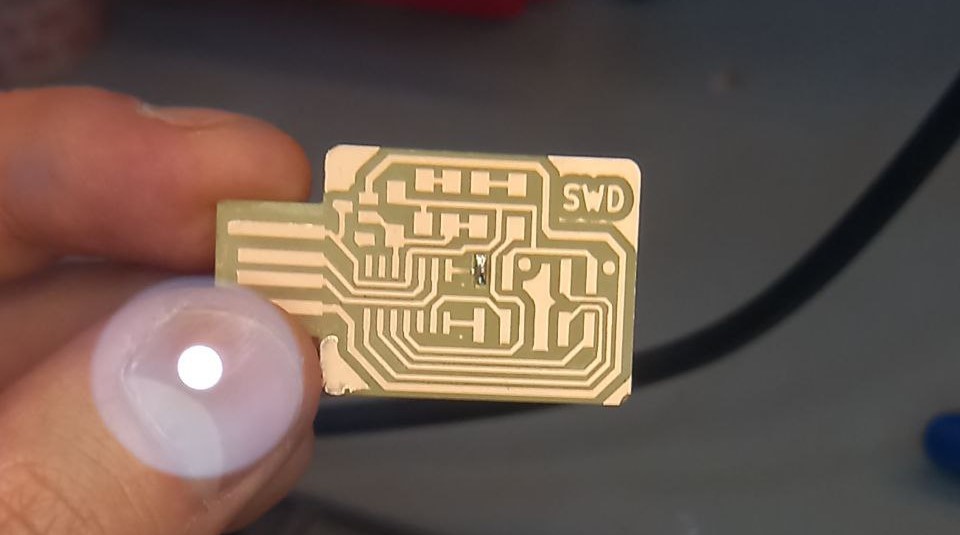
- Started from center for more convinient soldering.
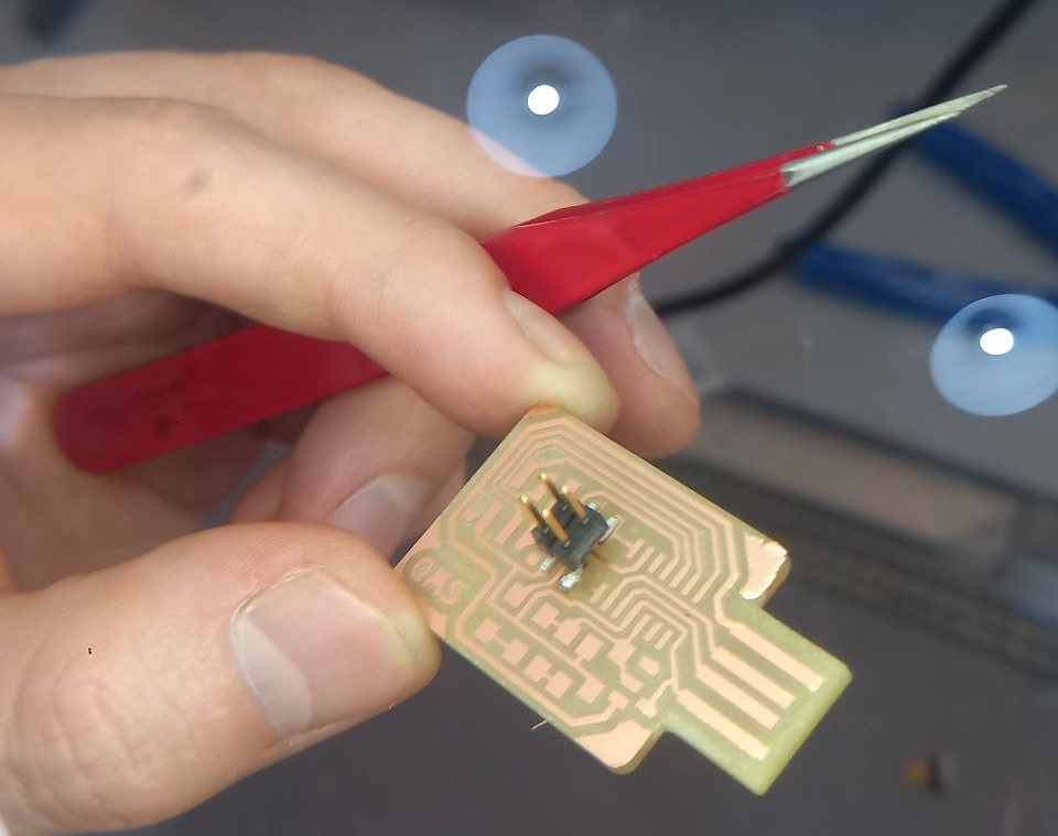
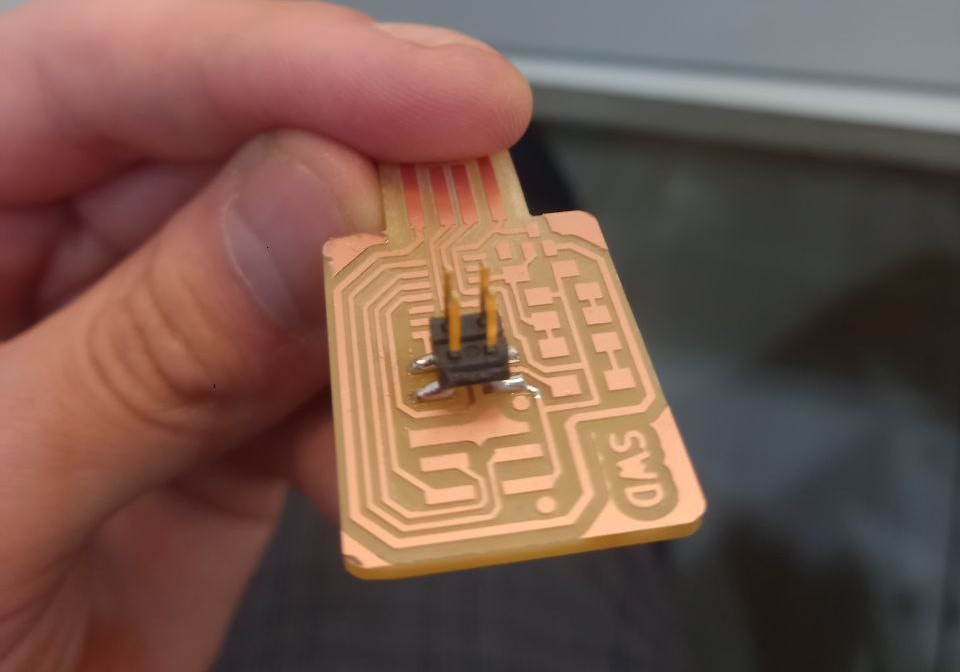
- Soldered first leg, than opposite, so on. Thought that probably not enough solder, added more.
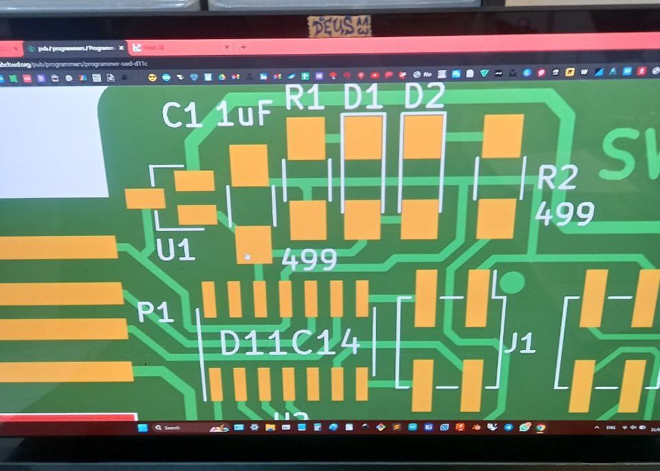
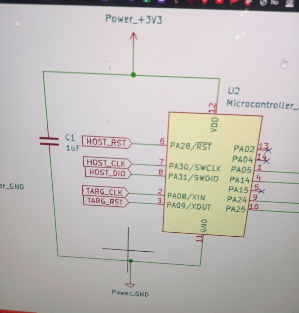
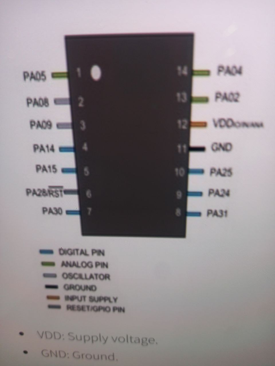
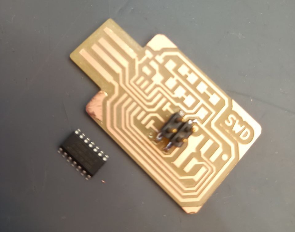
- After that decided to put SWD11C, it took some time to undredstood how to rotate it.
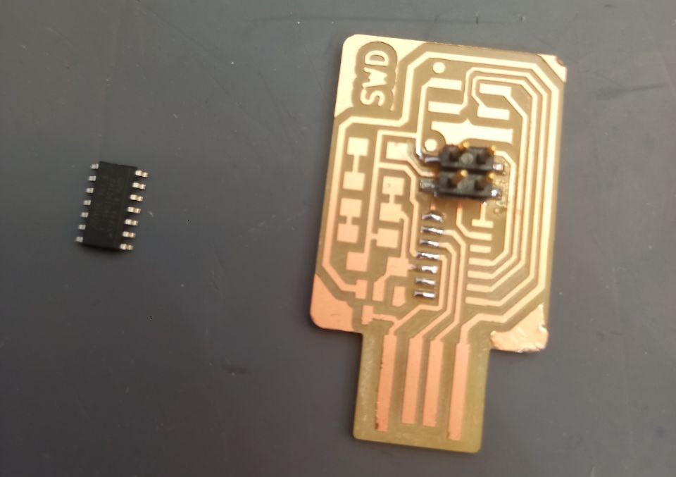
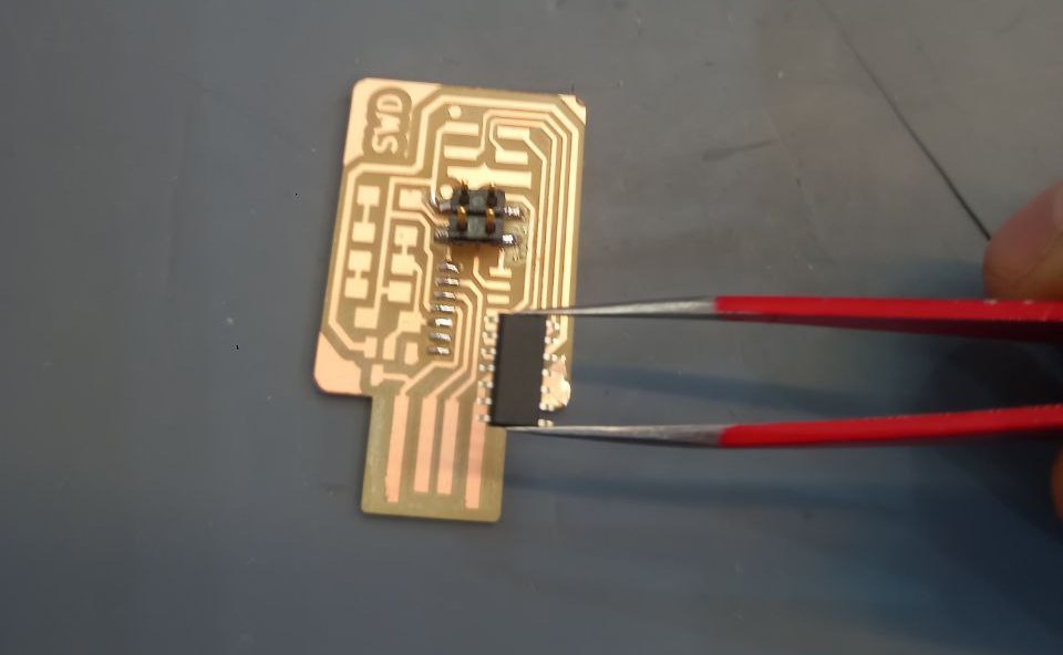
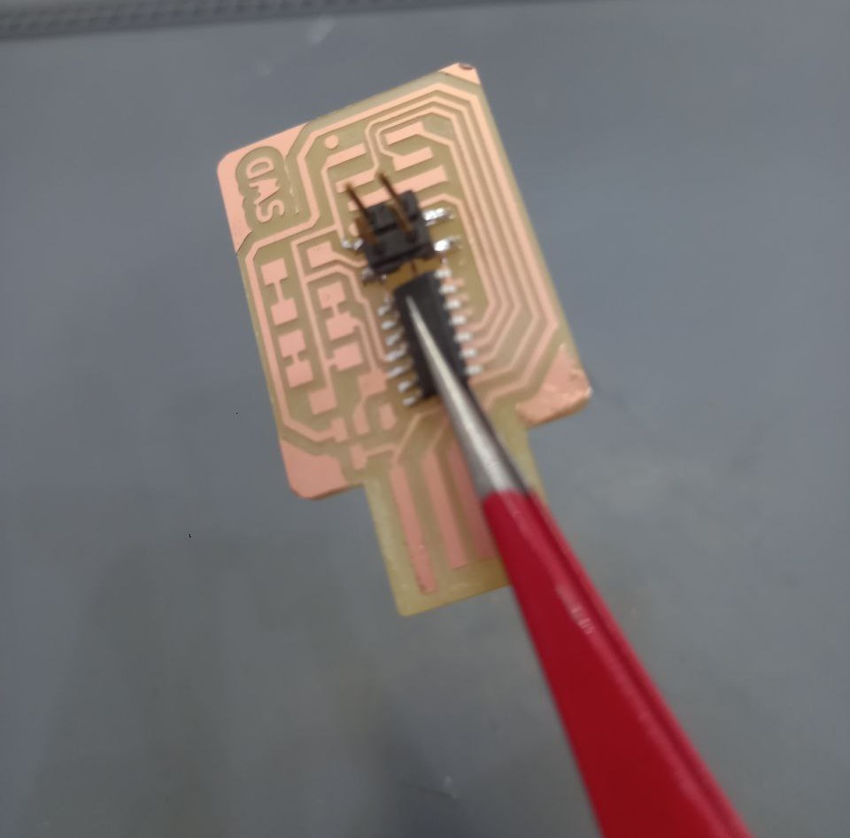
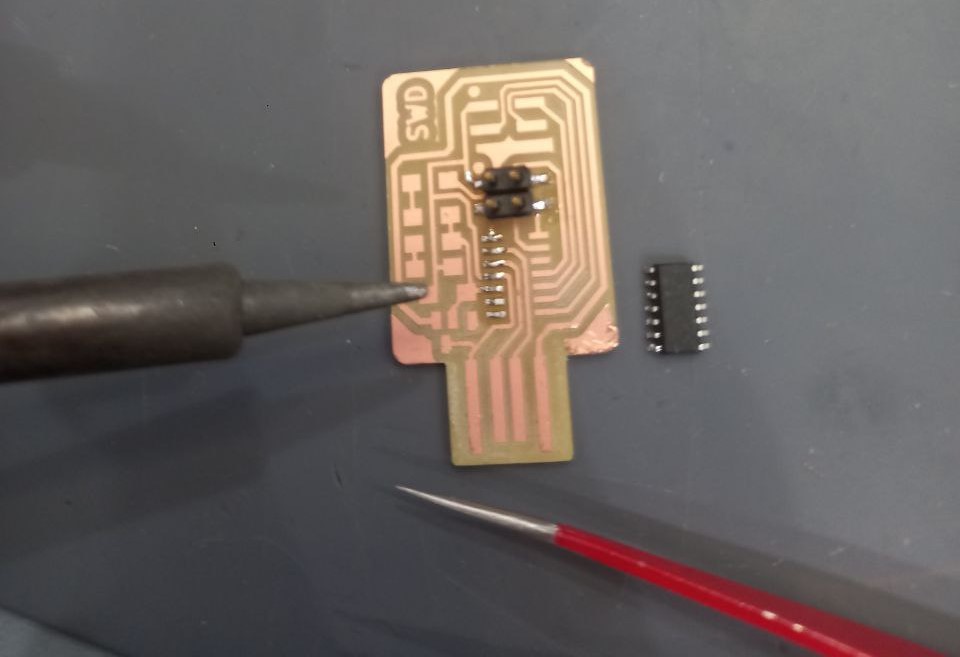
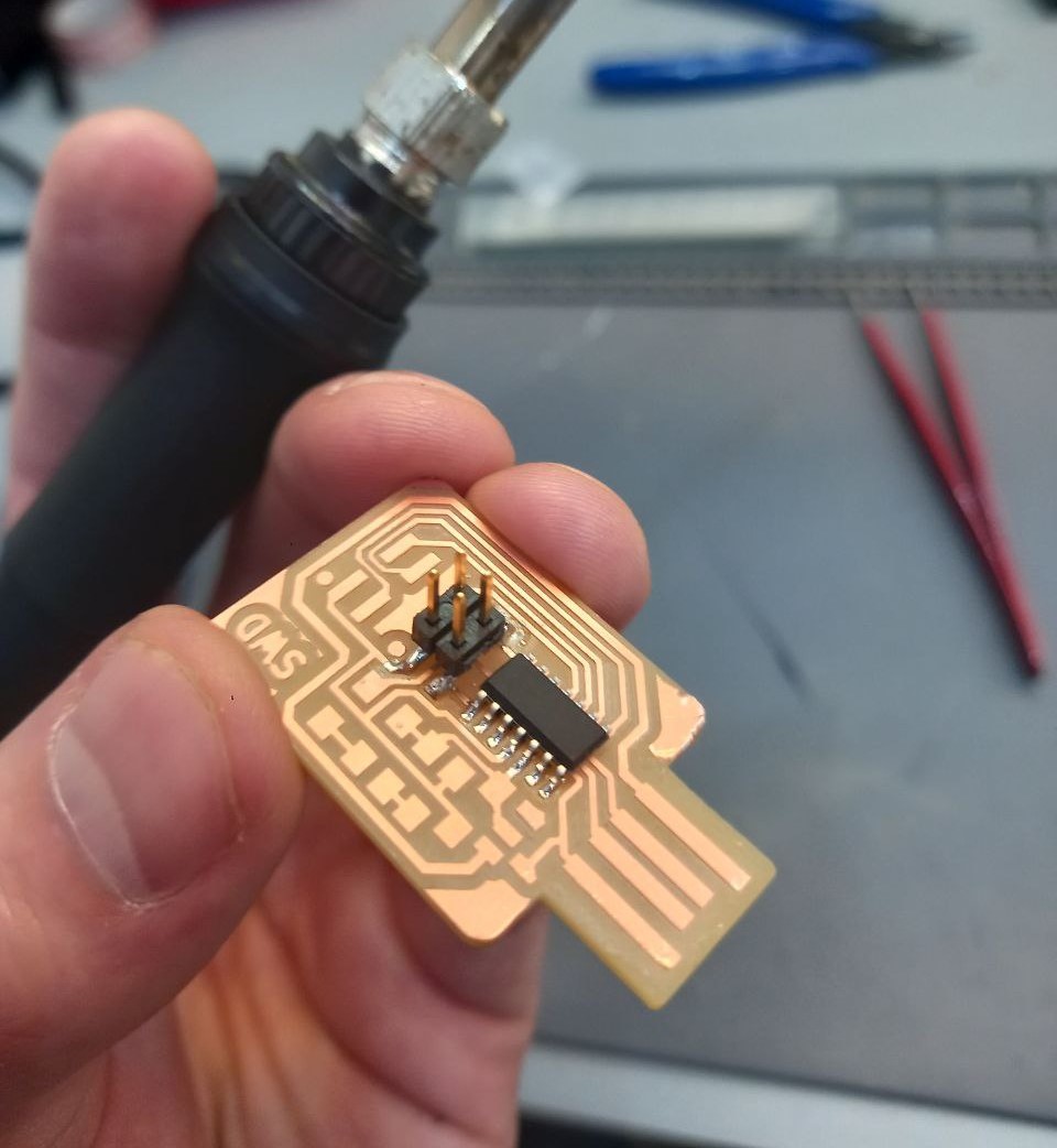
- When I found answer, put solder on pads and soldered controller legs in turn, finished first side and understood that at some moment rotated it and placed it incorrect), so dismantled it out by heating soldering iron flatwise and tweezers, in result legs curved, but not too strong. In result first side was done.
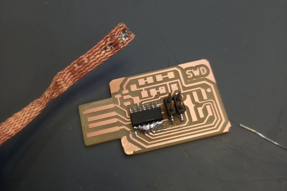
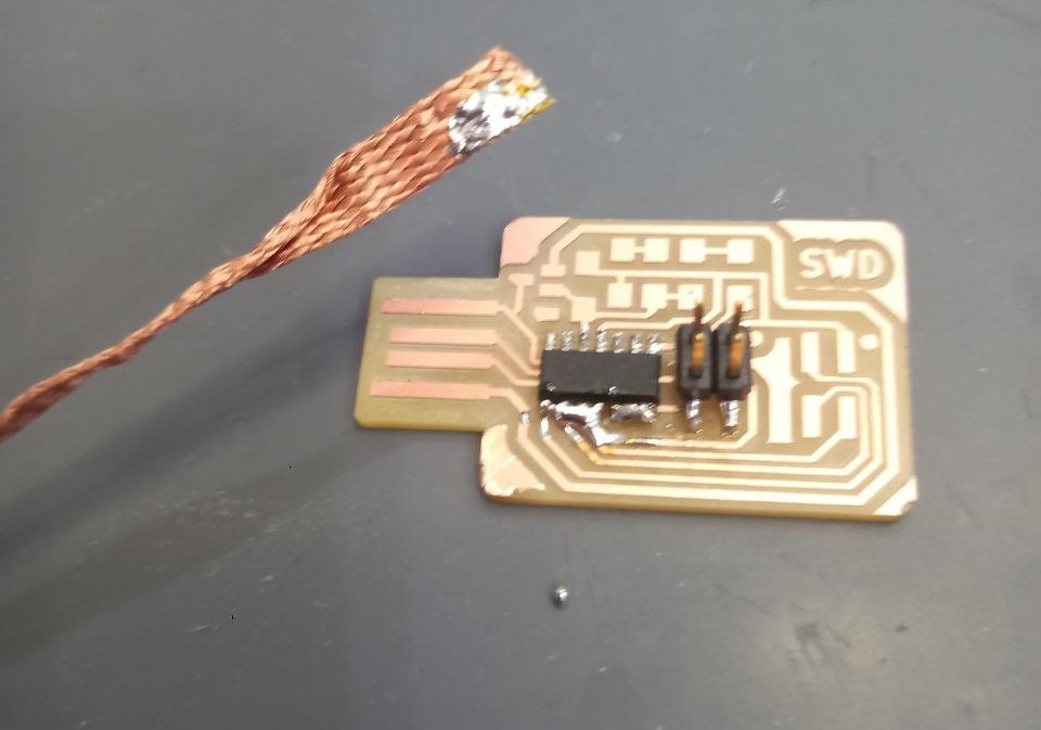
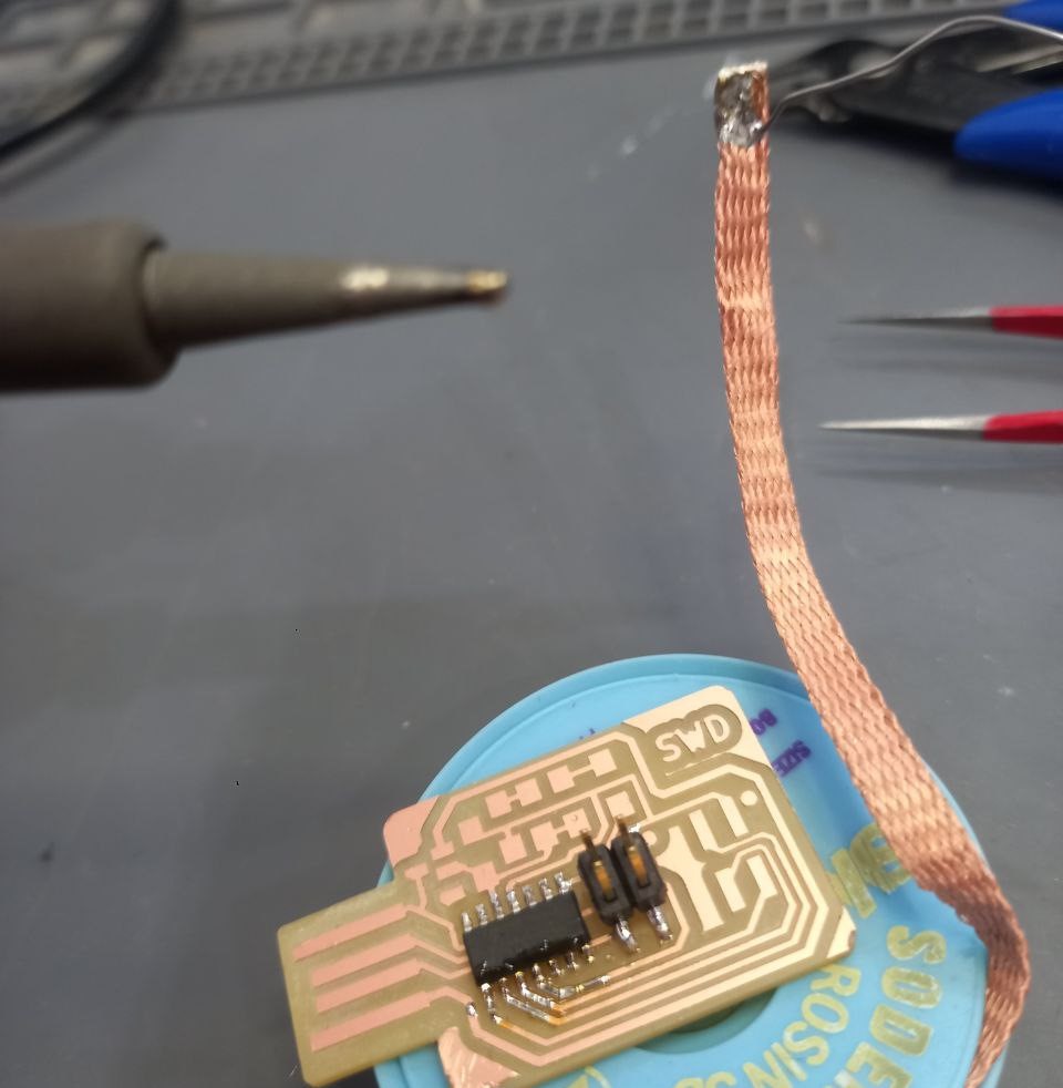
- Decided try to make second part by first using lots of solder and than remove its excess by wicker copper. Firstly it did not worked well, so I put some solder on wicker and than pressed down copper to excess of solder and started heating adding more solder from top (untill it did not merged inside wicker structure with excess).
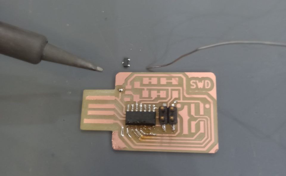
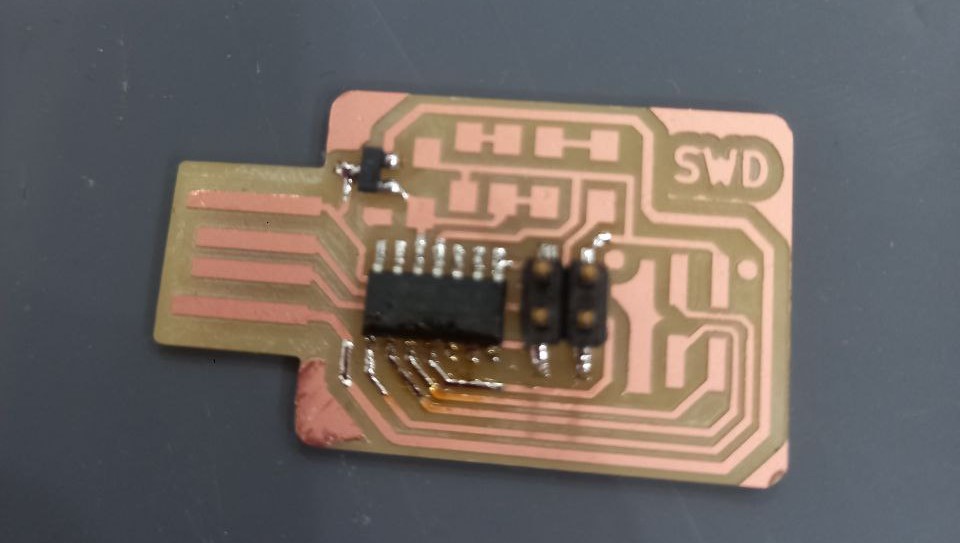
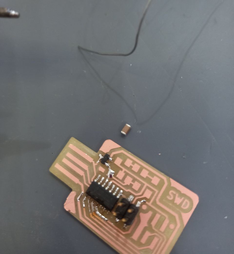
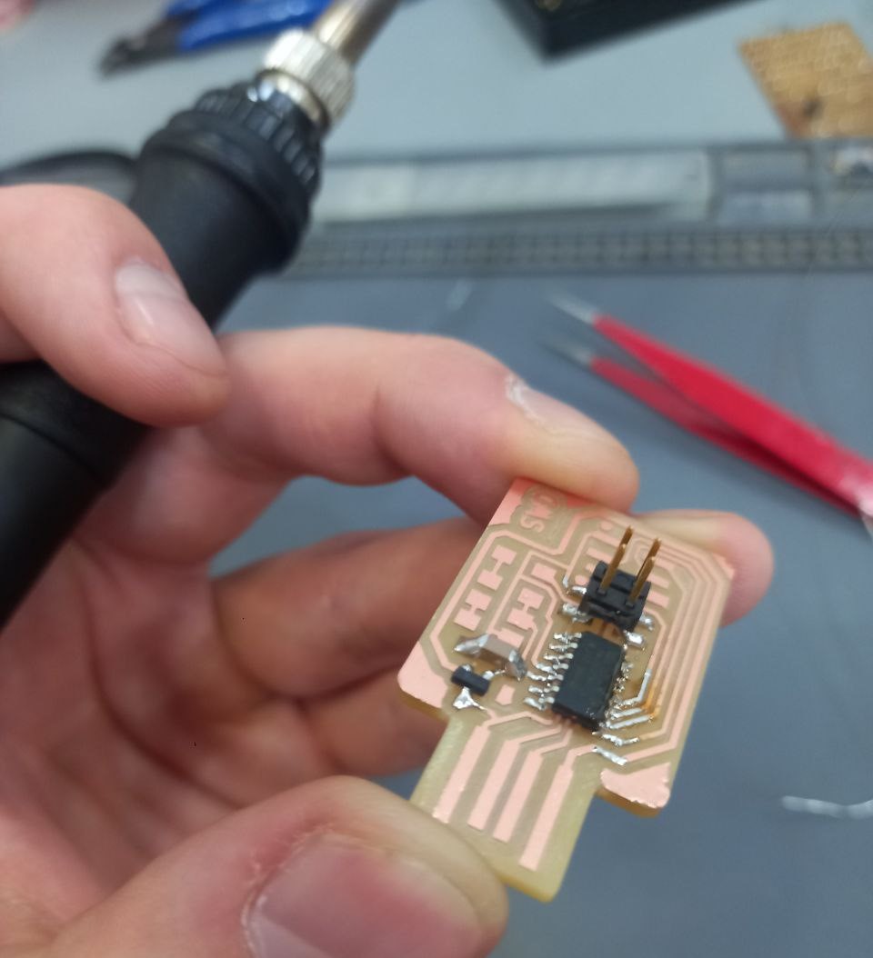
- After soldered voltage shifter and capacitor.
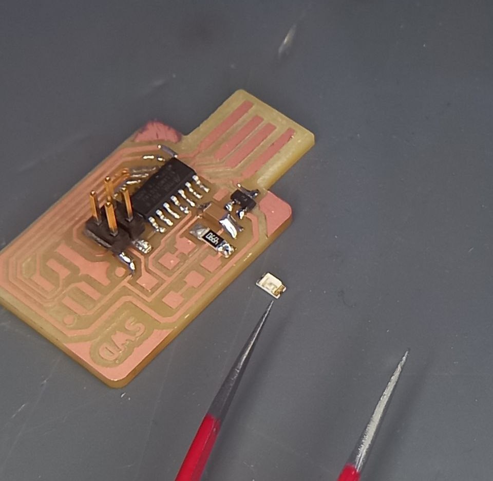
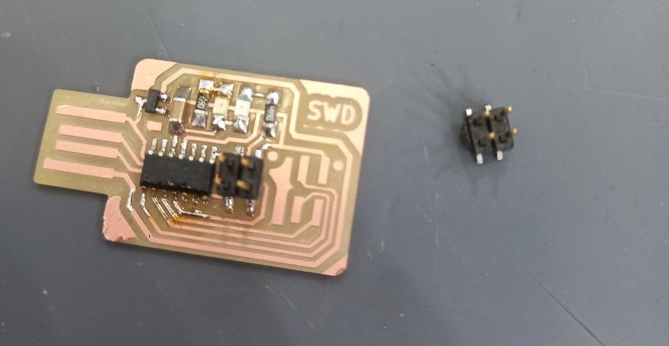
- Than first resistor and LED (when defined that green line is ground) and so on.
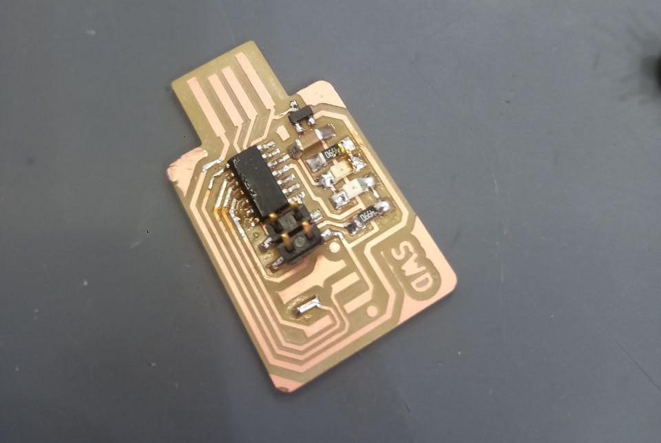
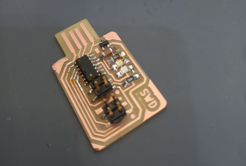
- Finaly soldered second 4-wire contact.
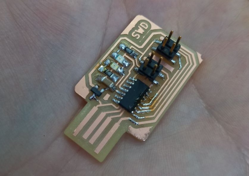
- Result looks litte bit burned, also should use less solder (as minimal to avoid metall bubbles, also one goldy contact of resistor is not fully covered by solder, better to avoid it). So, after checking by multimeter explored that gorund was soldered not well.
Programming
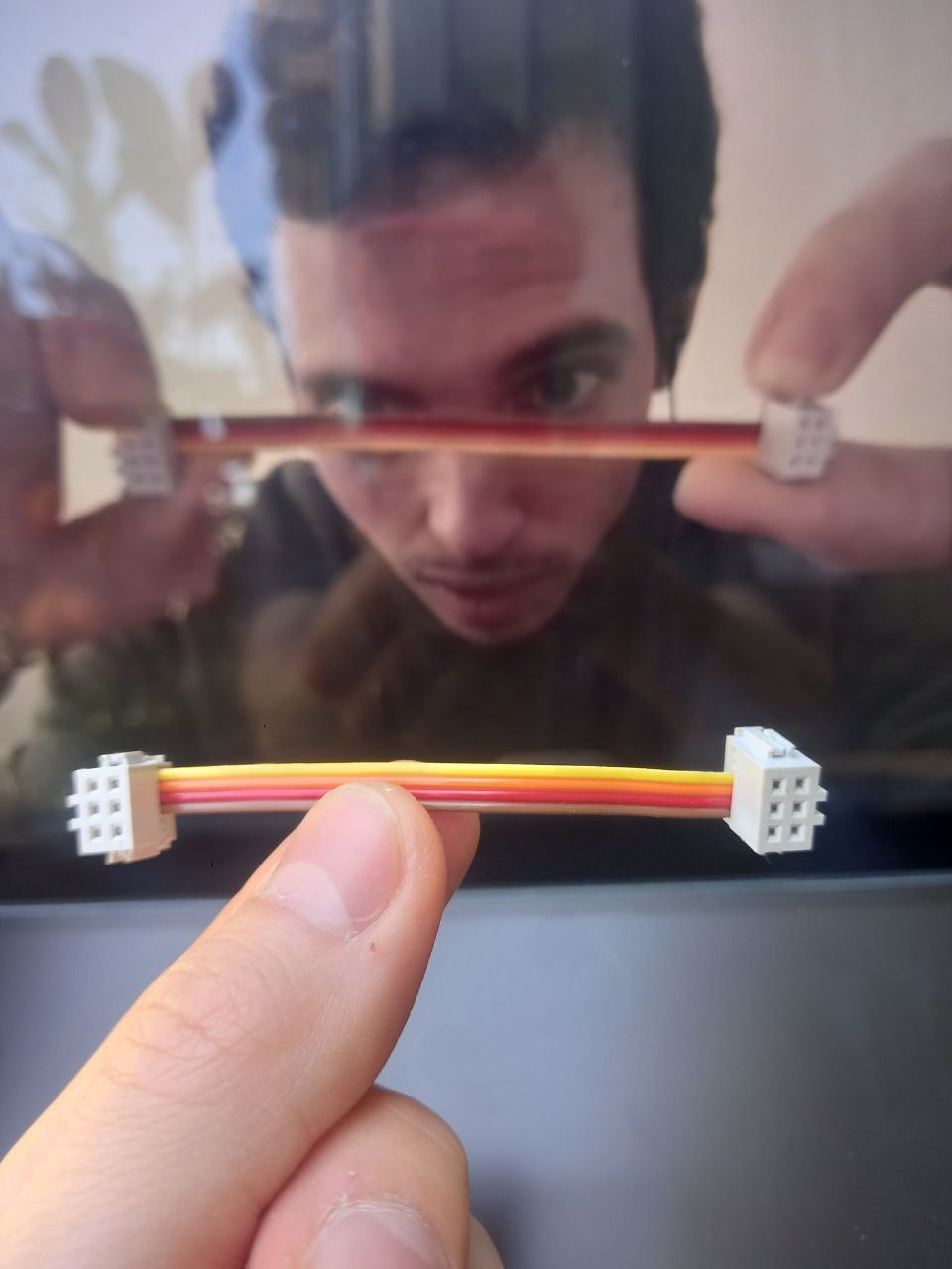
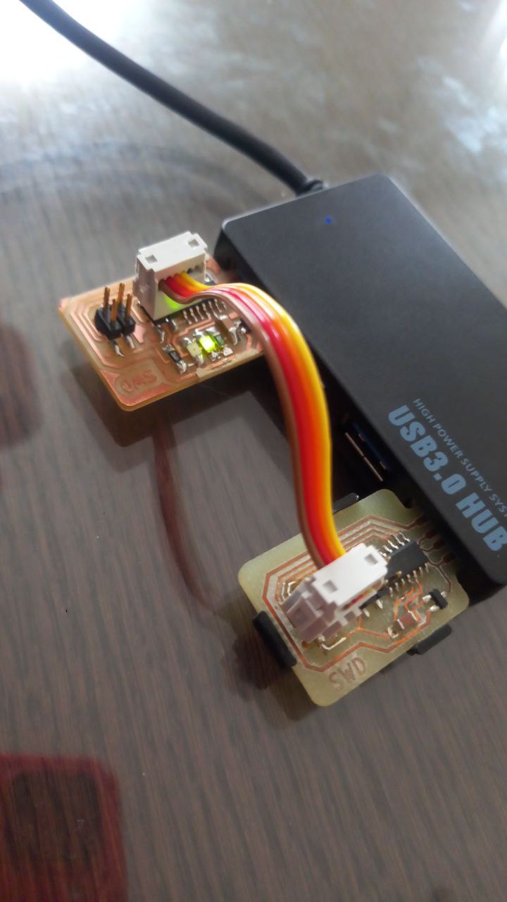
- Main principe for programming empty microcontoroler coppect pins parallel (corespond).
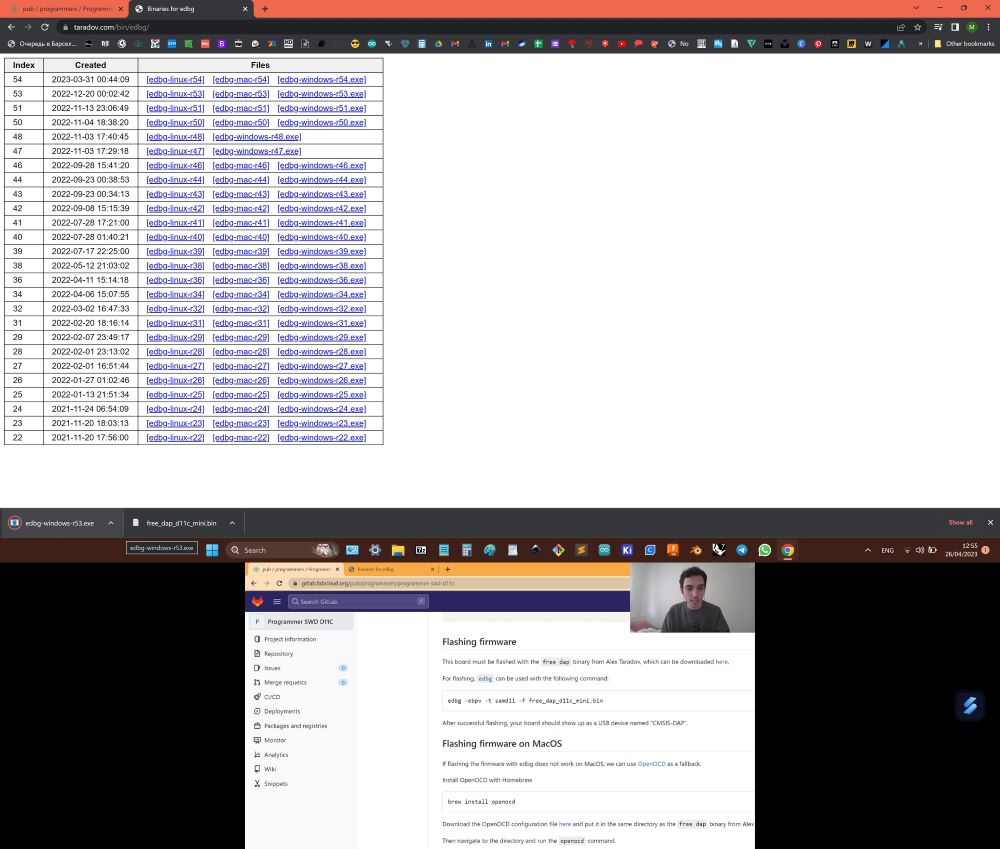
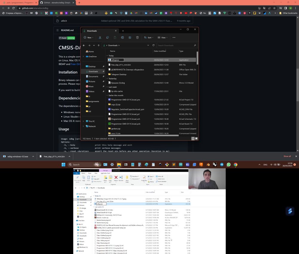
- Downloaded, renamed and placed in repository folder two files, one is "sam_ba_SAMD11C14A.bin" - programming code (for creation programmers with programmer), second is "free_dap_d11c_mini.bin" - software for microcontroller to recognise "C++" language complained by Arduino develop environment.
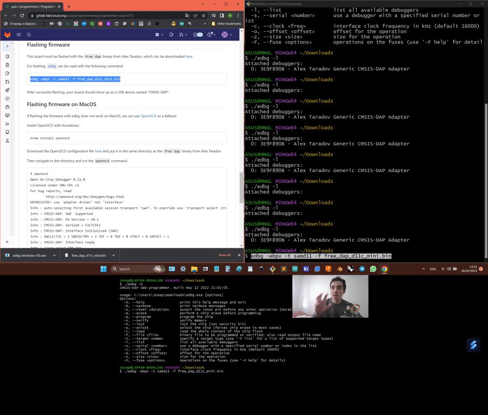
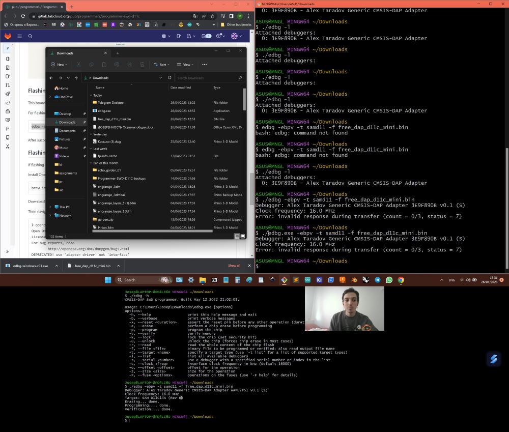
- Command " .edbg -l " showing how many conected microcontrollers have this soft, if it is empty, it will not see it will not show up.
- Command " edbg -ebpv -t samd11 -f sam_ba_SAMD11C14A.bin " erising memory and make micricontroller a programmer.
- Command " edbg -ebpv -t samd11 -f free_dap_d11c_mini.bin " erasing memory and flashing micricontroller for coding.
- First it did not work, because was not recognizing soldered board, reason was that ground was not soldered well, after fixation, programed successfuly.
Code
#define PIN_LED_W 4
#define PIN_LED_Y 2
#define ON_BUTTON 14
#define MODE_BUTTON 15

boolean onbuttonWasUp = true;
boolean modebuttonWasUp = true;
boolean ledEnabled = false;
boolean onoff ;
int mode;

void setup()
{
  Serial.begin(9600);
  pinMode(4, OUTPUT);
  pinMode(2, OUTPUT);
  pinMode(15, INPUT_PULLUP);
  pinMode(14, INPUT_PULLUP);
}

void loop()
{

    boolean onbuttonIsUp = digitalRead(14);             // find out if the button is currently released

    if (onbuttonWasUp && !onbuttonIsUp);                // if the button was released and not released now
    {
      delay(10);                                        // exclude the bounce of the contacts of the clock button
      onbuttonIsUp = digitalRead(14);                   // and read the signal from the button again

      if (!onbuttonIsUp)
      { // if the button is pressed, then flip the LED signal
          ledEnabled = !ledEnabled;
          onoff = !ledEnabled;
          digitalWrite(4, ledEnabled);
          digitalWrite(2, ledEnabled);
      }
    }

    onbuttonWasUp = onbuttonIsUp;                       // store button state for new iteration
    delay(200);

    boolean modebuttonIsUp = digitalRead(15);           // find out if the button is currently released

        if (modebuttonWasUp && !modebuttonIsUp);        // if the button was released and not released now
        {
          delay(10);                                    // exclude the bounce of the contacts of the clock button
          modebuttonIsUp = digitalRead(15);             // and read the signal from the button again

          if (!modebuttonIsUp && onoff == false)
          {
              mode = mode + 1;                          // counter of running position is incremented by 1

              if (mode == 4)
              {mode = 0;}                               // if the counter limit is reached then reset

              switch (mode)                              //selection operator, executes its block depending on the value of the variable

              {
              case 0:
              digitalWrite(2,ledEnabled);
              digitalWrite(4,ledEnabled);
                return;

              case 1:
              digitalWrite(2,ledEnabled);
              digitalWrite(4,LOW);
                return;

              case 2:
              digitalWrite(2,LOW);
              digitalWrite(4,ledEnabled);
                return;
              }
          }
        }

}
Video
Video