Week 11. Input devices
This week I worked with a data entry device configured with the microcontroller that, together with the code, output values of the temperature sensor are observed.
Assignments
Group assignment:
- Probe an input device(s)’s analog levels and digital signals.
- Document your work on the group work page and reflect on your individual page what you learned.
Individual assignments:
- Measure something: add a sensor to a microcontroller board that you have designed and read it.
Group assignment
- In addition, you can see here and below the group work that we carried out virtually together with my fellow students Renso Samaniego, Ronal Vilca Grace Schwan, all connected from the city of Huánuco, Cerro de Pasco and Lima. Link
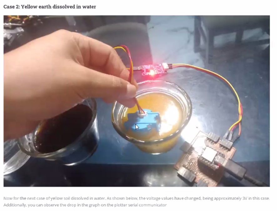 In the group work, colleague Ronal shows the testing of the turbidity of the water with dye using a sensor.
 I test the turbidity of coffee water using a sensor.
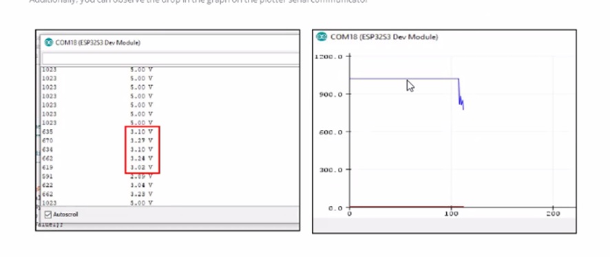 Result shown from the first experiment
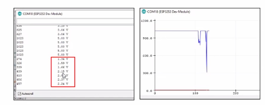 Result shown from the second experiment
 Result displayed on value scale
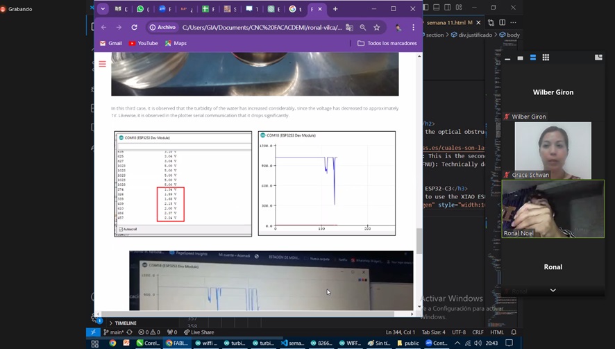
 Values observed on the website in real time when the microcontroller is synchronized by Wi-Fi
 Showing the steps to configure a serial plotter monitor.
 Showing results on serial plotter screen.
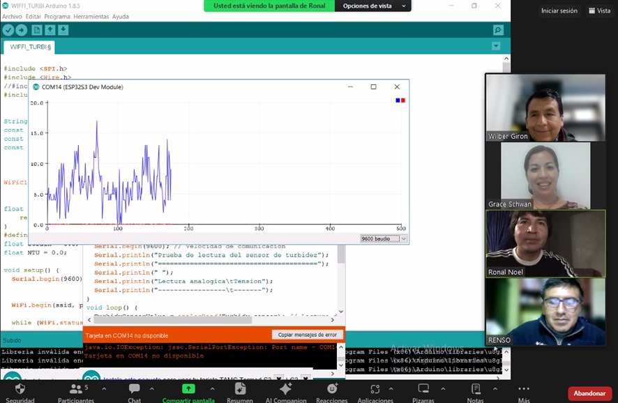 Seeing the parallel the monitor and the code.
 The source of the code that moves everything on connected devices.
Individual assignment
- For this week in this individual, use an analog sensor to perform the ambient temperature change tests and display the result using the temperature sensor.
Learning outcomes
- Demonstrate workflows used in sensing something with input device(s) and MCU board

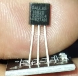
DS18B20 Sensor de Temperatura Digital
FEATURES
-
Unique 1-Wire interface requires only one port pin for communication
-
Multidrop capability simplifies distributed temperature sensing applications
-
Requires no external components
-
Can be powered from data line. Power supply range is 3.0V to 5.5V
-
Zero standby power required
-
Measures temperatures from -55°C to +125°C. Fahrenheit equivalent is -67°F to +257°F
-
±0.5°C accuracy from -10°C to +85°C
-
Thermometer resolution is programmable from 9 to 12 bits
-
Converts 12-bit temperature to digital word in 750 ms (max.)
-
User-definable, nonvolatile temperature alarm settings
-
Alarm search command identifies and addresses devices whose temperature is outside of programmed limits (temperature alarm condition)
-
Applications include thermostatic controls, industrial systems, consumer products, thermometers, or any thermally sensitive system
 Starting the steps to install the chosen sensor library.
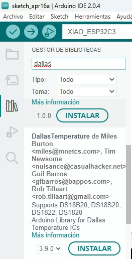
Looking for the device brand on the arduino ide.
 We observe the completion of the library installation.
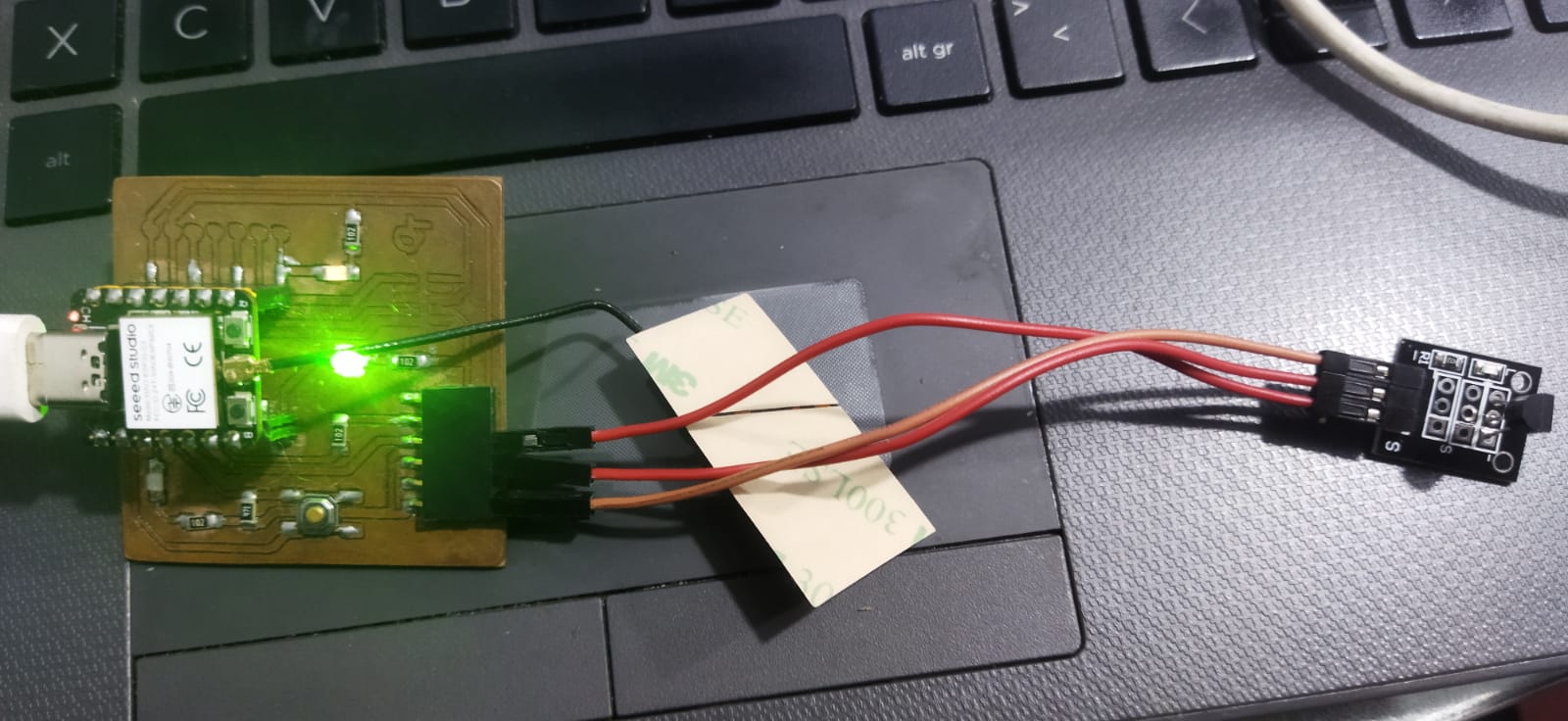 Connectivity used between the quetorres card and the temperature sensor module.
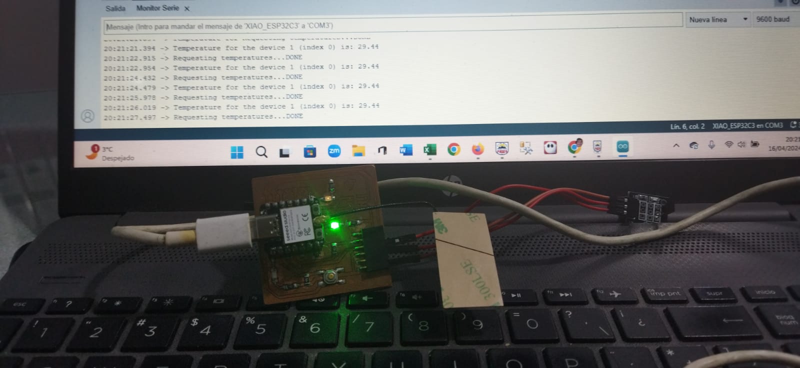 Value one of the temperature perceived in degrees Celsius by the sensor and its display on the screen.
 Value two of the temperature perceived in degrees Celsius by the sensor and its display on the screen
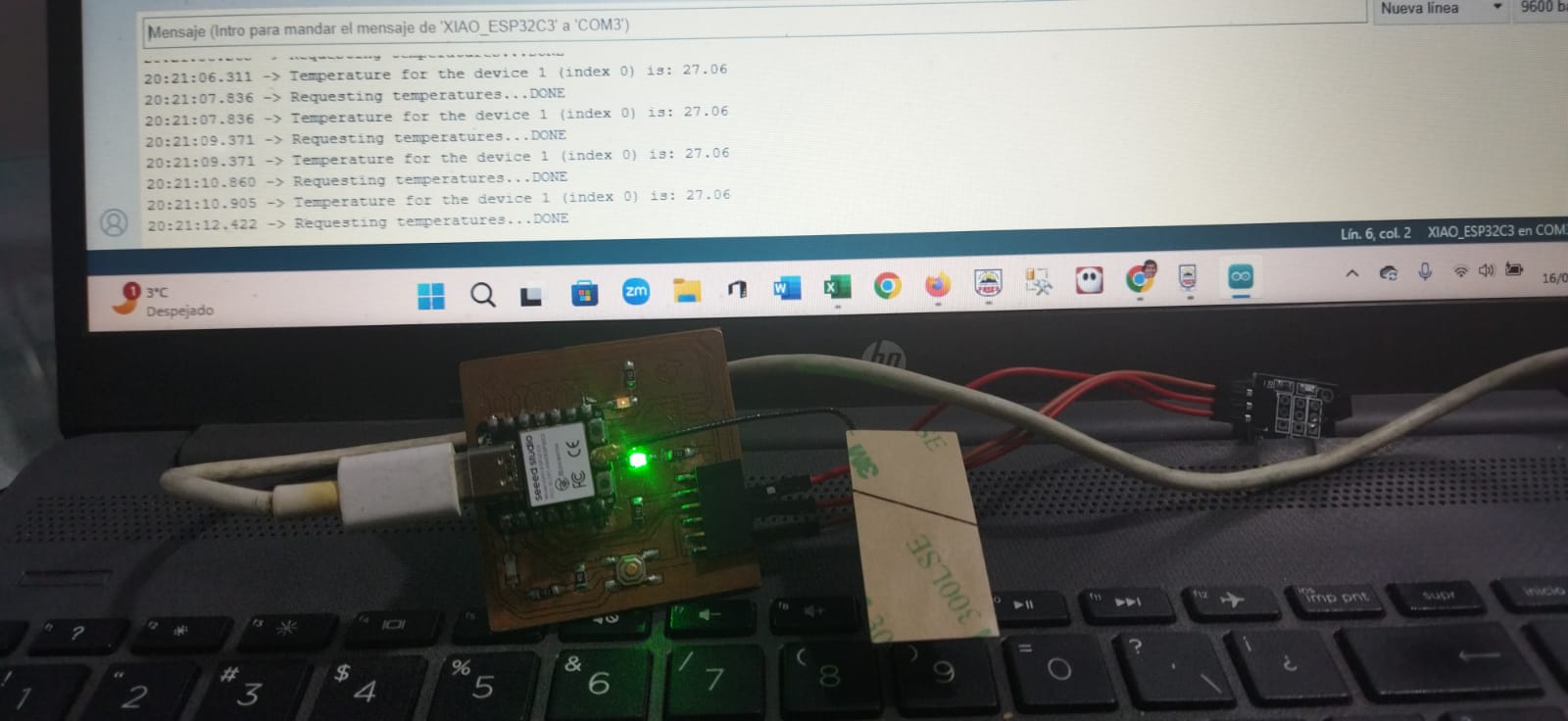 Value three of the temperature perceived in degrees Celsius by the sensor and its display on the screen.
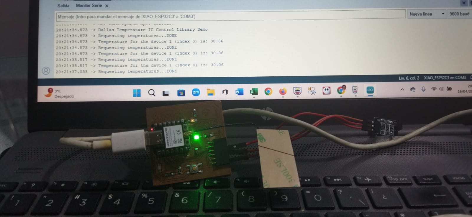 Value four of the temperature perceived in degrees Celsius by the sensor and its display on the screen.
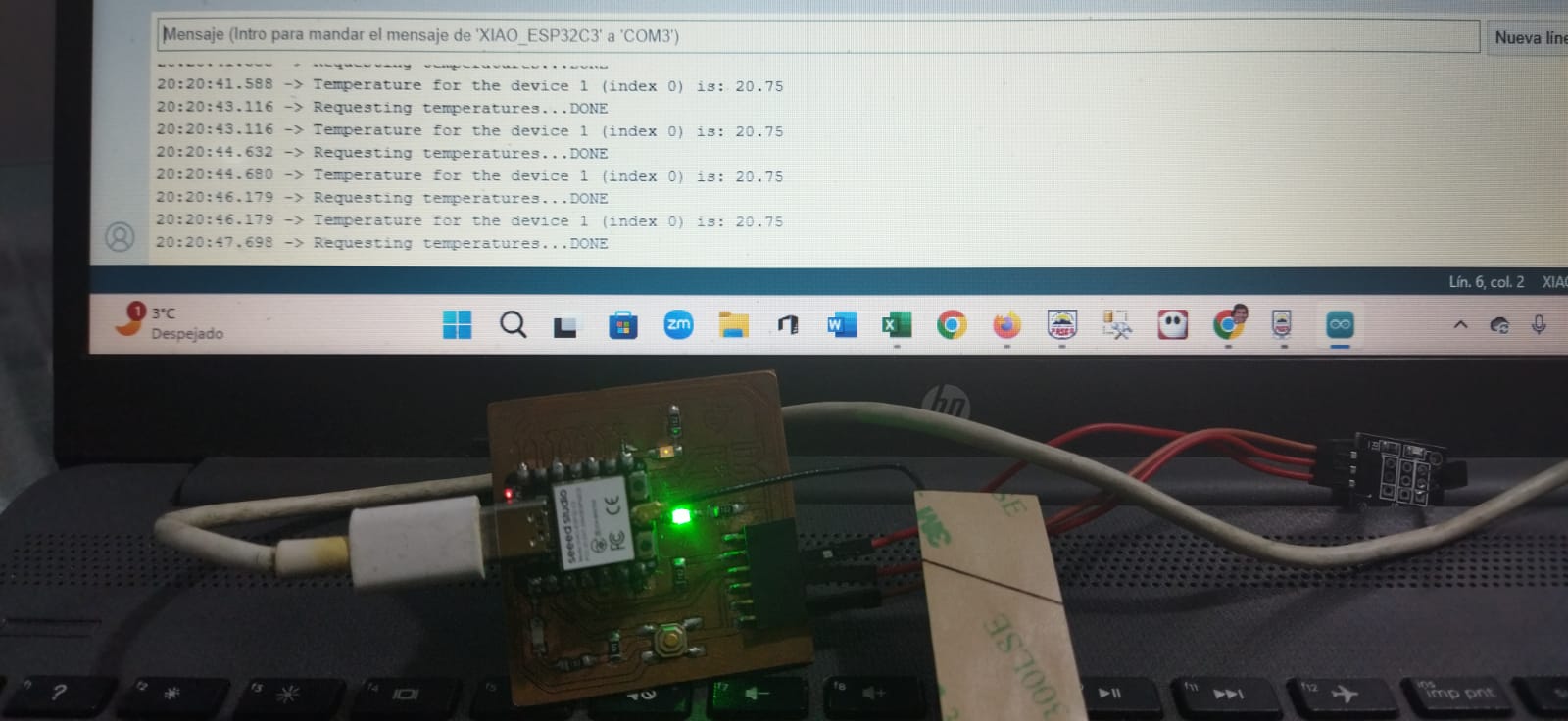 Value five of the temperature perceived in degrees Celsius by the sensor and its display on the screen.
Use Link
- Datasheet Website where the characteristics of the sensor were obtained.
Code
The following code written in arduino ide that uses two libraries that belong to the temperature sensor, and then connecting to the Xiao Esp32 C3 microcontroller.
// Include the libraries we need
#include <OneWire.h>
#include <DallasTemperature.h>
// Data wire is plugged into port 2 on the Arduino
#define ONE_WIRE_BUS D2
// Setup a oneWire instance to communicate with any OneWire devices (not just Maxim/Dallas temperature ICs)
OneWire oneWire(ONE_WIRE_BUS);
// Pass our oneWire reference to Dallas Temperature.
DallasTemperature sensors(&oneWire);
void setup(void)
{
  // start serial port
  Serial.begin(9600);
  Serial.println("Dallas Temperature IC Control Library Demo");
  // Start up the library
  sensors.begin();
}
/*
 * Main function, get and show the temperature
 */
void loop(void)
{
  // call sensors.requestTemperatures() to issue a global temperature
  // request to all devices on the bus
  Serial.print("Requesting temperatures...");
  sensors.requestTemperatures(); // Send the command to get temperatures
  Serial.println("DONE");
  // After we got the temperatures, we can print them here.
  // We use the function ByIndex, and as an example get the temperature from the first sensor only.
  float tempC = sensors.getTempCByIndex(0);

  // Check if reading was successful
  if(tempC != DEVICE_DISCONNECTED_C)
  {
    Serial.print("Temperature for the device 1 (index 0) is: ");
    Serial.println(tempC);
    delay(1500);
  }
  else
  {
    Serial.println("Error: Could not read temperature data");
  }
}
Conclusions
- Regarding accuracy and reliability The DS18B20 offers accurate temperature measurements with a resolution of up to 0.0625°C and a wide range (-55°C to +125°C), making it suitable for environmental control applications, process monitoring, and IoT projects. In practice, we were able to observe temperatures within the range shown
- According to Ease of Implementation, its digital design (1-Wire protocol) allows for easy connection and reduces the number of pins required on the microcontroller, which simplifies the design of the hardware or board.
- In Potential Limitations Although it is versatile, its response time may not be ideal for applications where temperature changes occur quickly. In addition, it requires calibration in certain extreme environments to maintain accuracy.
- In Energy Savings, its low power consumption makes it ideal for battery-powered systems, increasing the energy efficiency of the system in general.
- In practical applications, this sensor is ideal for monitoring in homes, offices, as heating and cooling control, industrial automation projects, medical devices and educational experiments, highlighting its flexibility in various environments.
- In individual work I learned how to capture the signal using the monitor on the Arduino program screen where the temperature values were displayed that changed as the sensor read high or low temperature data.
- In group work I learned that using the water turbidity sensor you can obtain data on a graphic and numerical scale that ranges from the most turbid to the clearest of the liquid element.