Week 3. Computer controlled cutting
In this process we are going to carry out the first steps to verify when the laser focus to the surface is at a good height and observe what is appropriate for the subsequent cut.
Assignments
Group assignments:
- Characterize your lasercutter’s focus, power, speed, rate, kerf, joint clearance and types.
- Document your work to the group work page and reflect on your individual page what you learned.
Individual assignments:
- Design, lasercut, and document a parametric construction kit, accounting for the lasercutter kerf, which can be assembled in multiple ways.
- Cut something on the vinyl cutter.
Learning Outcomes
- Demonstrate and describe parametric 2D modelling processes.
- Identify and explain processes involved in using the laser cutter.
- Develop, evaluate and construct a parametric construction kit.
- Identify and explain processes involved in using the vinyl cutter.
Group assignments:
In this activity I can share the experience of designing, configuring and cutting the following activity on the laser machine.
Designing the comb
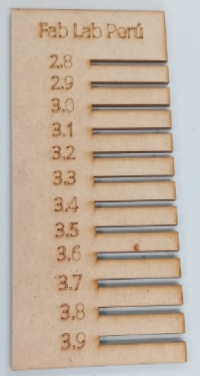
We designed the comb with a width of 100 millimeters by 190.2 millimeters long in 3mm thick MDF material, using the online program onshape.
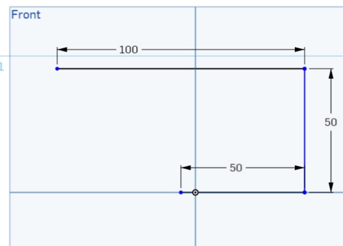
In this first phase, the comb was designed with a width of 100 millimetres and a length starting at 50 millimetres.
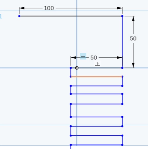
Then the other teeth were designed with different dimensions.
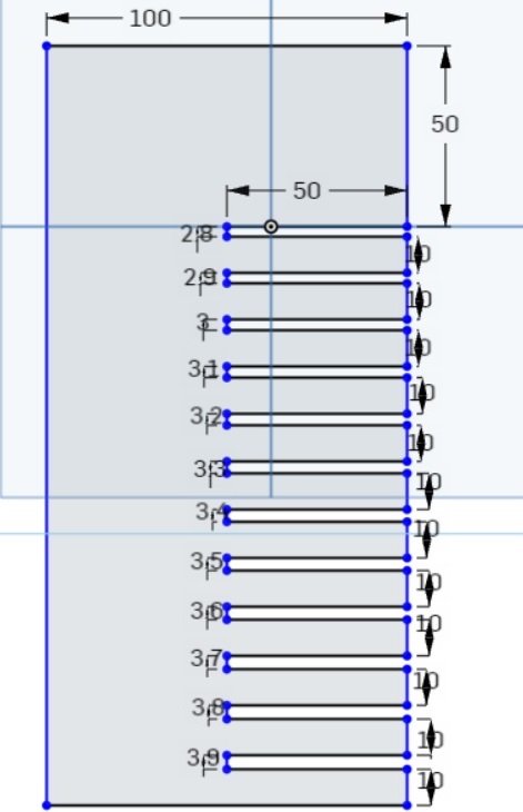
It was modified from 50 to 30 millimeters in length and the next one was from 2.8 millimeters and from there increasing 1 millimeter for each tooth.
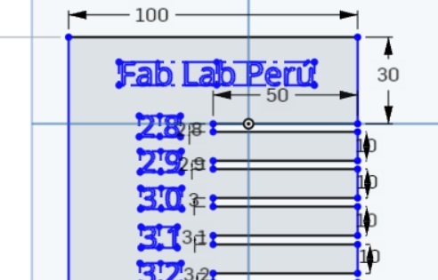
Added Fab Lab Peru text as shown in the image.
 And finally we can see after cutting the MDF material converted into a comb.
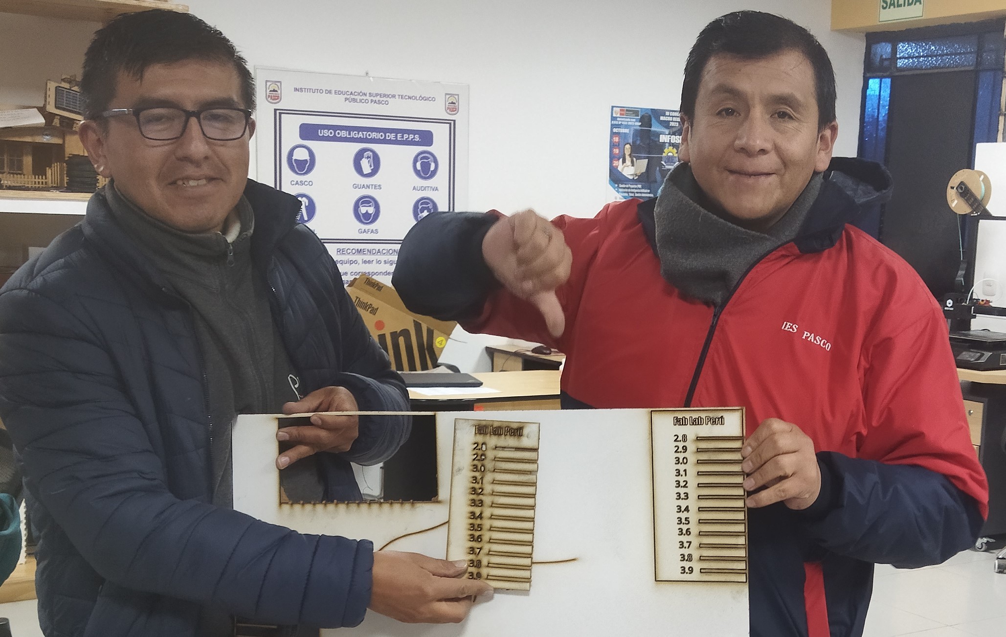
This process shows the printing of two combs, the one that came out well was configured with a power of 80 and the one that did not manage to cut at all was configured with a power of 70, it did not manage to go through the material.
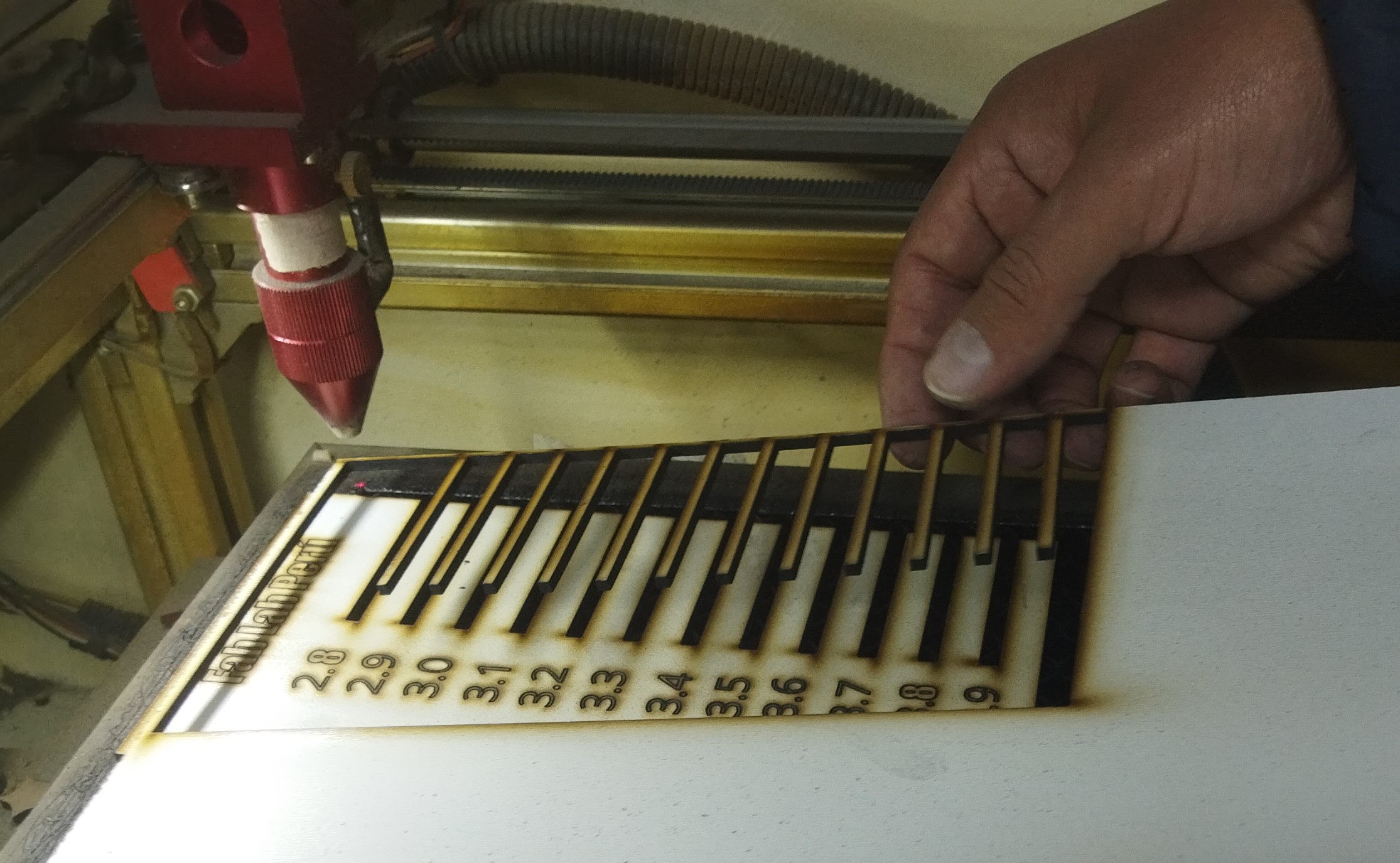
Removing the material and as shown the cut goes through the material with 80 power.
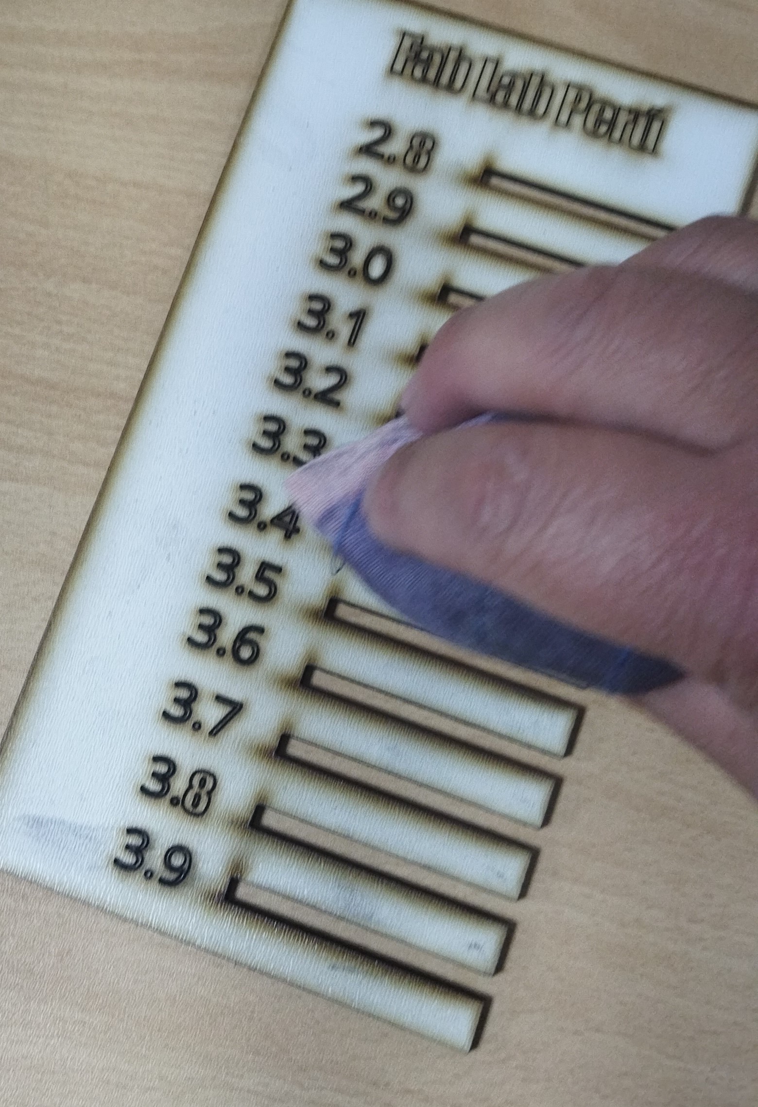
Carrying out the respective cleaning to see in detail the coret lines and the measurements of the teeth of the combs that only recorded with a power of 40.
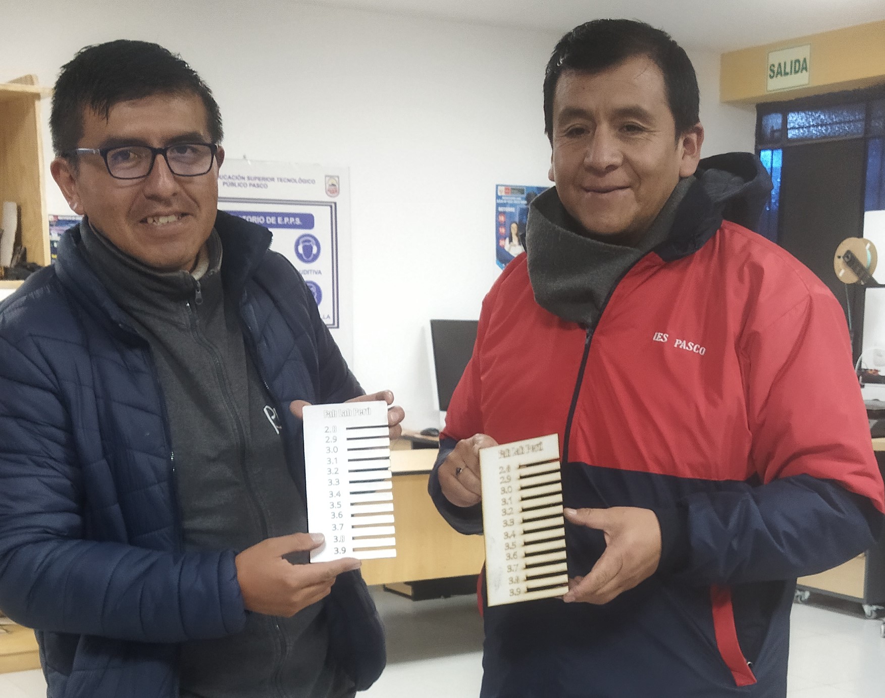
And finally, demonstrating the group work together with my partner Renso Samaniego
Individual assignments:
For that design an object of different height dimensions to do the test
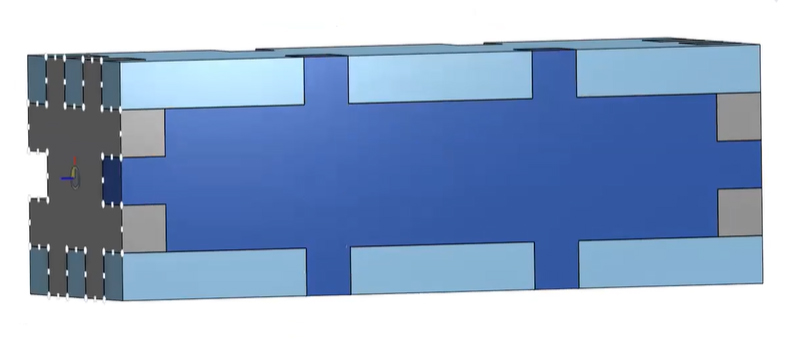
Step 1: Step 1: We enter the Onshape program and observe the designed object.
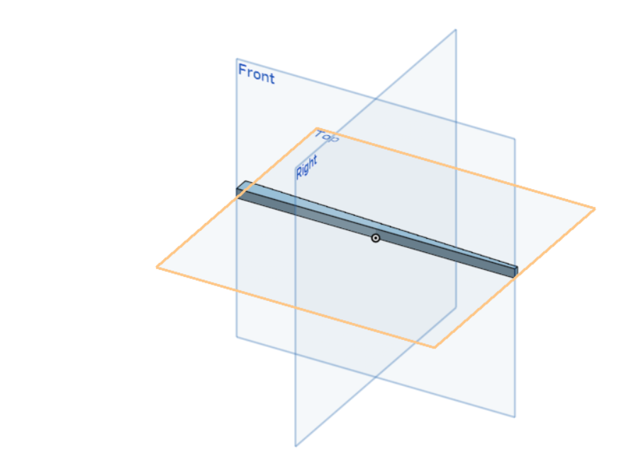
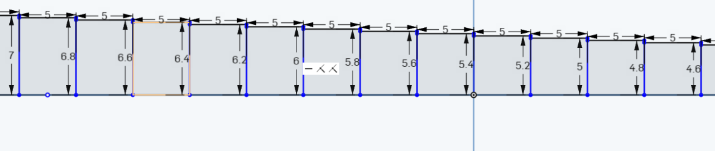
Step 2: In front view we see the different dimensions of the design.

Step 3: Already observing more closely we see the difference in height of 2 millimeters.

Step 4: Once again the design view object showing the different dimensions in millimeters.
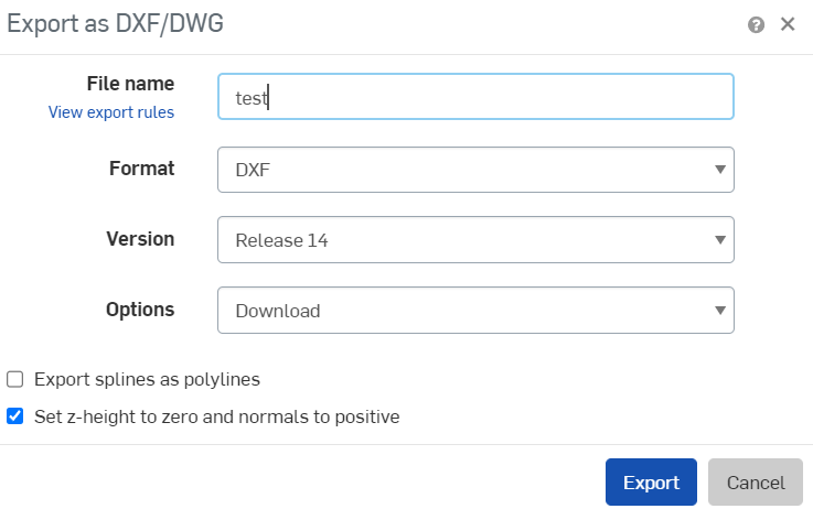
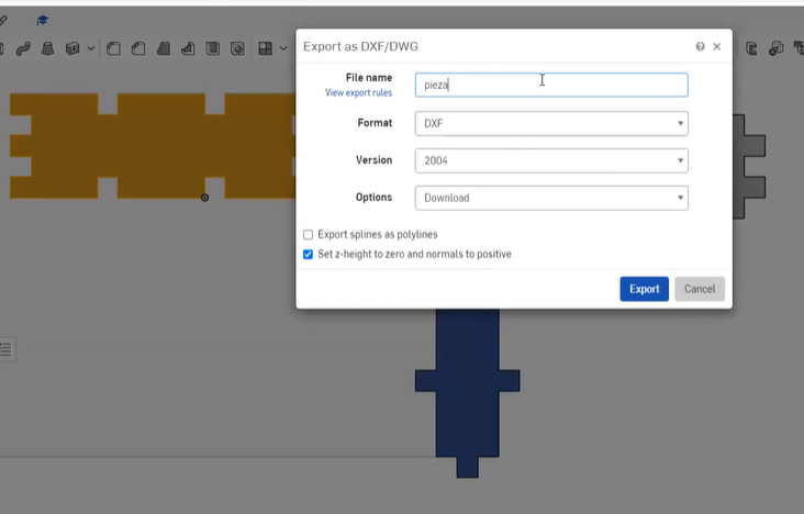
Step 5: Preparing the designed object to be exported as a DXF.

Step 6: We place in the next window the name of the file to export it and see the type of file chosen.
Step 7: We open the CNC Laser program to then import the generated file
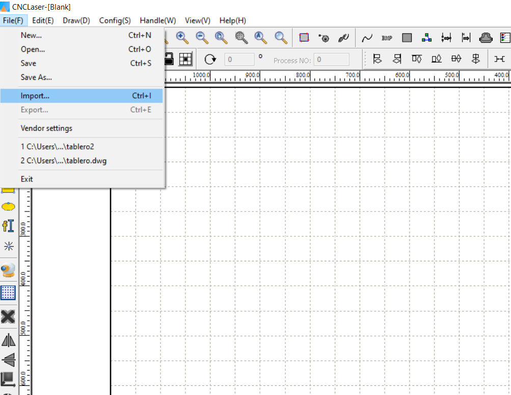
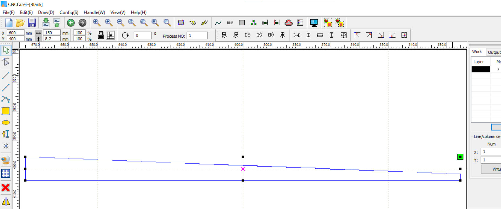
Step 8: In this image we can see the exported file made previously in Onshape
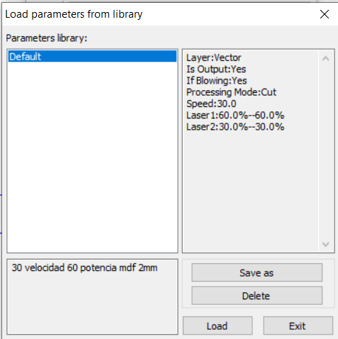
Step 9: In this image we can load the default values to continue for the cut.
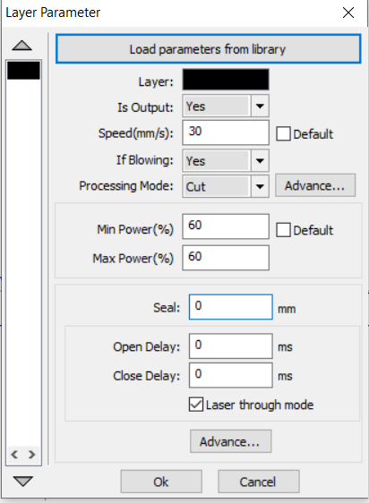
Step 10: Once the values for the cut have been loaded, we proceed by pressing OK.
Gallery Design of a parametric drawing, cutting and assembly
In this week’s homework I will show the advanced parametric design of a rectangular figure, working with the design in onshape software, and then printing it with a laser cutter.
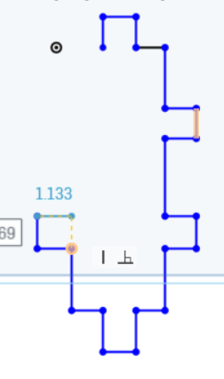
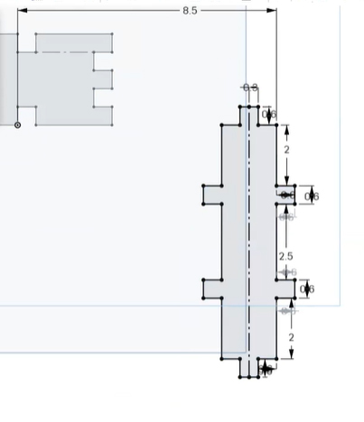
Initially, I was beginning to design the lateral part of the figure with the measurements that are observed in the onshape program.
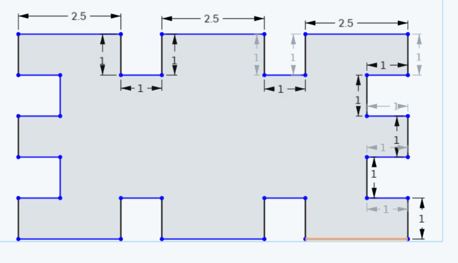
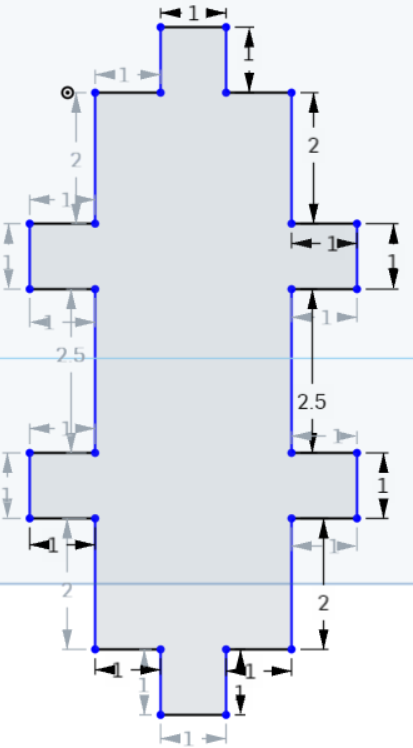
In this second image you can already see all the dimensions of the sides of the figure that will go on the side.
This figure will fit on both sides of the first figure that has been designed
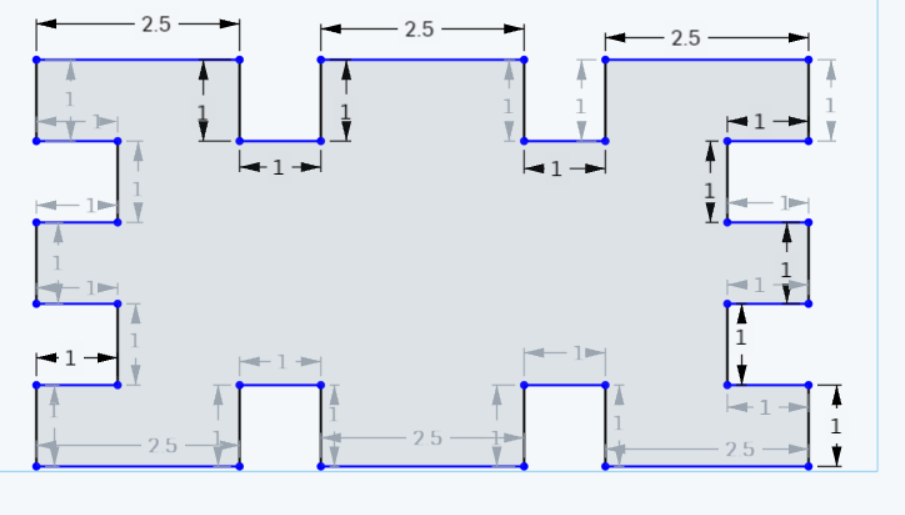
Here we already have it with its dimensions already completed from the second figure to be assembled.
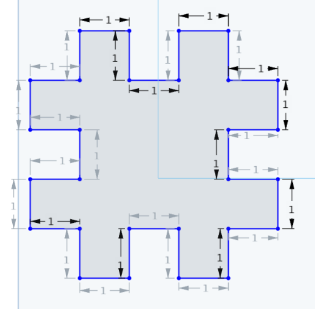
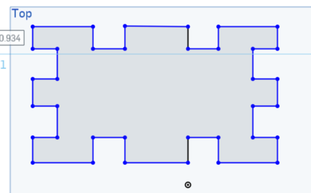
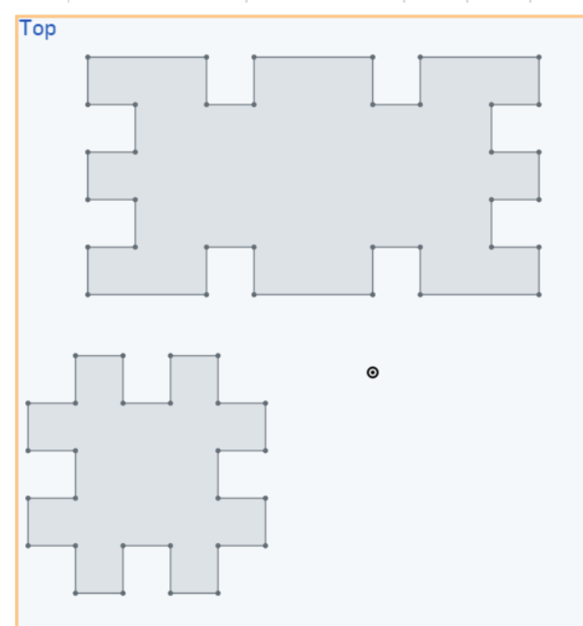
This figure shows the design from the top view of the two figures already designed with their respective measurements.
The design of part 3 that will cover the assembly of the previous two.
Here it is shown that the third finished piece with its assigned measurements
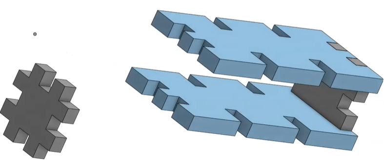
After experimenting in the first phase we begin to design how the final product will look:
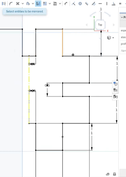
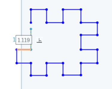
Designing in the first scketh of my design drawn in onshape using symmetry to help in the design.
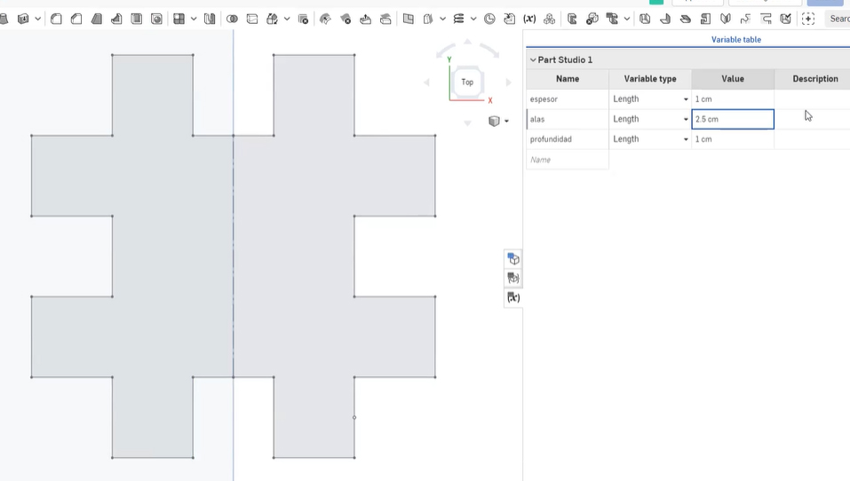 Already the finished design with symmetry has only had to be designed on one side and fifty percent has been implemented alone.
In the process I made errors of giving wrong values on one of the sides and consequently it has been fixed properly on only one side and the other one was updated automatically.
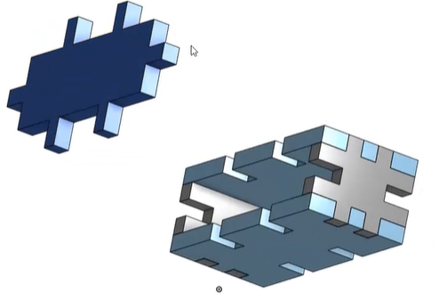
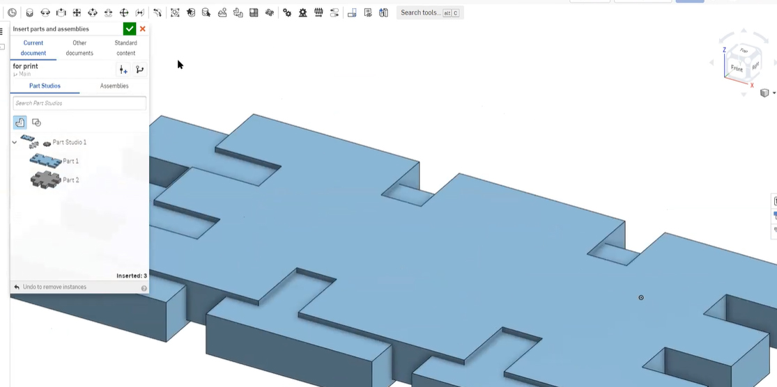 This is the screenshot after finishing designing 3 elements that would cover the box, testing the assembly.
 Once the three elements are finished, we align the x and y axes with the best fit to obtain.
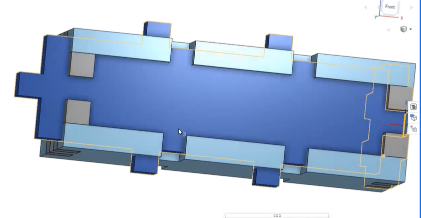
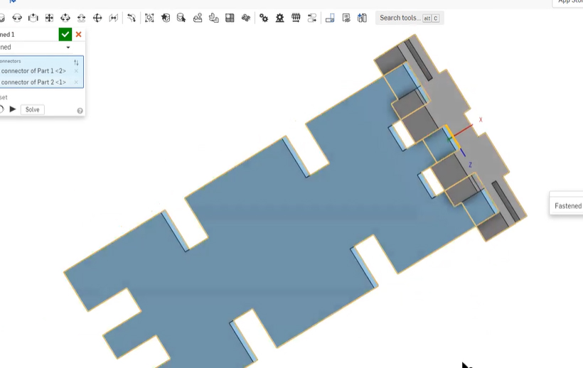 In the assembly process, we visually observed that there were still errors to be corrected in the design.
In the image it can be seen that when incorporating the three blocks there are still obvious errors to be corrected.
Finding even more bugs in the assembly process.
Finding less and less errors in the joins.
Showing the last piece for its respective union.
Finding in the last piece a measurement error that makes us need to make decisions for the change.
Making the last changes in the design mode with respect to the values to set.
Finally the expected assembly after several changes especially after gaining experience in development, trial - error.
 Complete Case Assembly
 Exporting the designs made to resize them to reality and configuring before cutting.
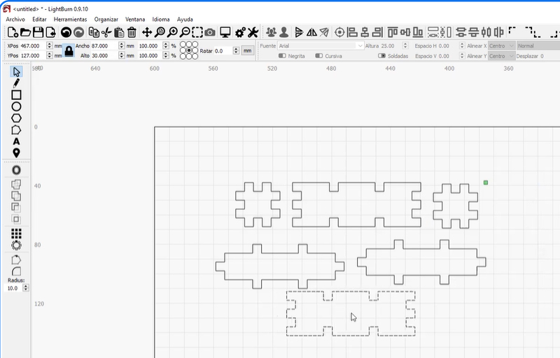 Preparing the six figures to be cut.
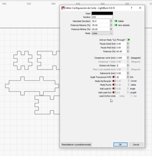 Configuring the last parameters before sending to the cut.
Parametric design
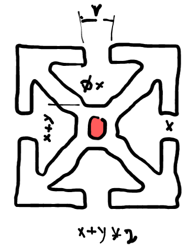
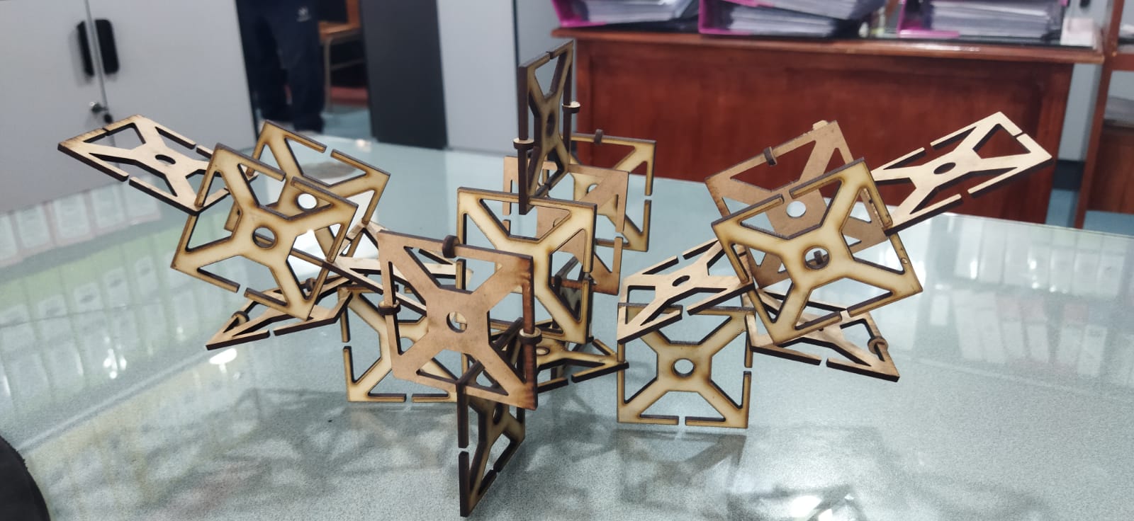
I thought about this box that can be replicated and assembles different figures when they are tilted at different degrees.
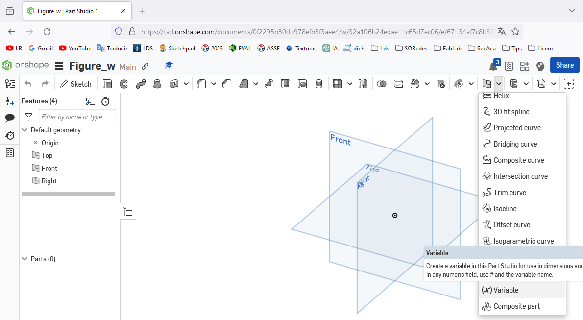
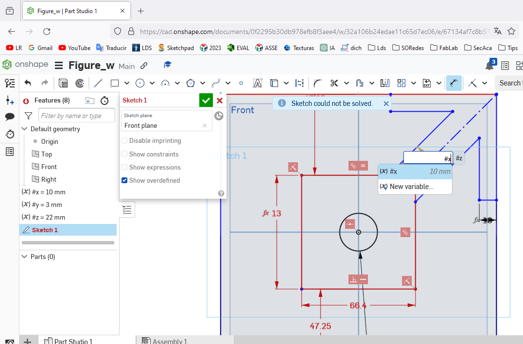
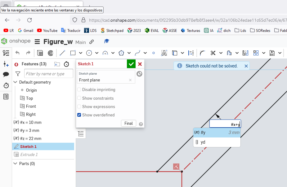
I chose the variable option to then add parametric values to the sides of the figure
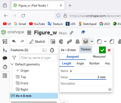
Assign the variable x the numerical value of 2 millimeters.
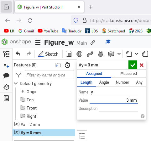
Assign the variable y the numerical value of 3 millimeters.
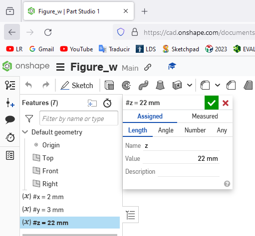
Assign the variable z the numerical value of 22 millimeters.
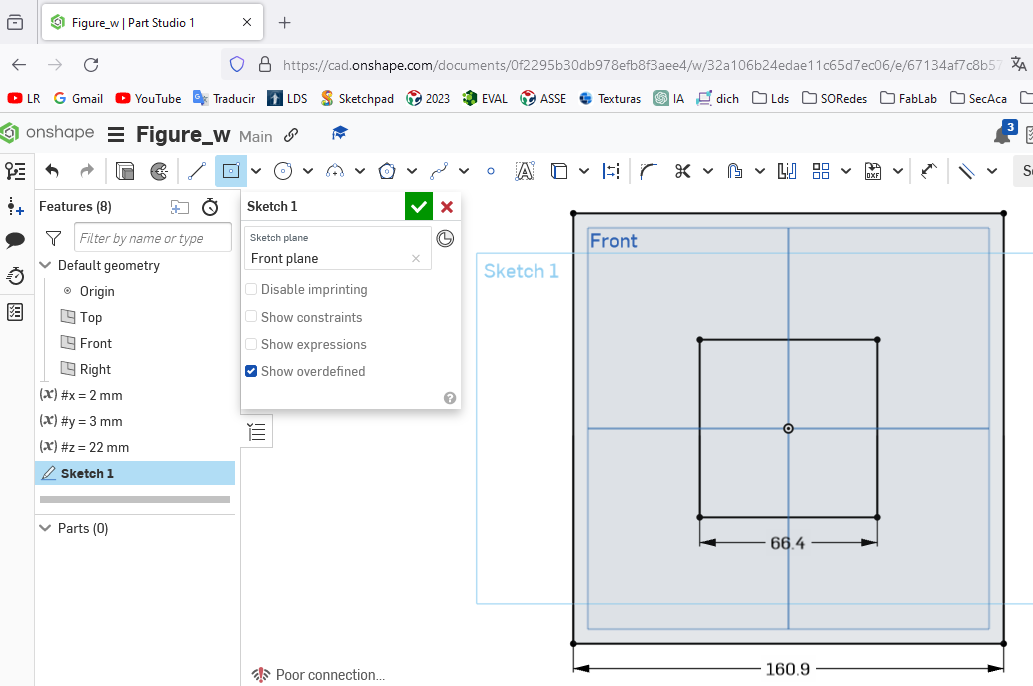
Drawing two squares with origin from the middle with side values of 66.4 millimeters and 160.9 as seen in the figure
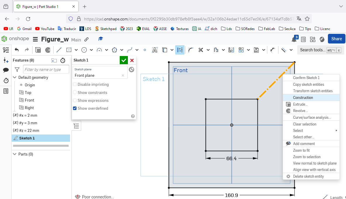
A guide line was drawn joining the two vertices.
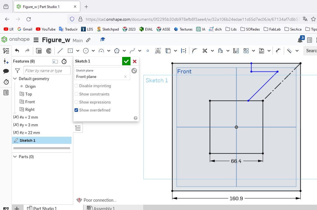
One side was drawn parallel to the base to the guide line
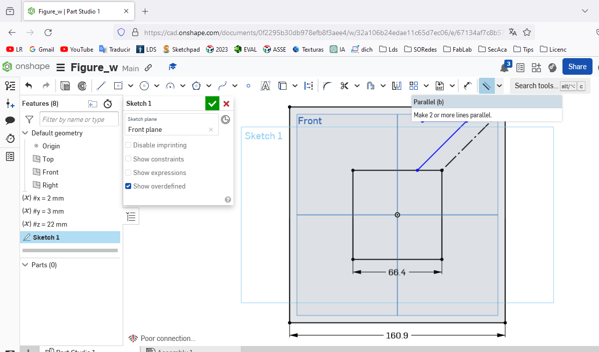
The parallel lines were defined based on the first line drawn
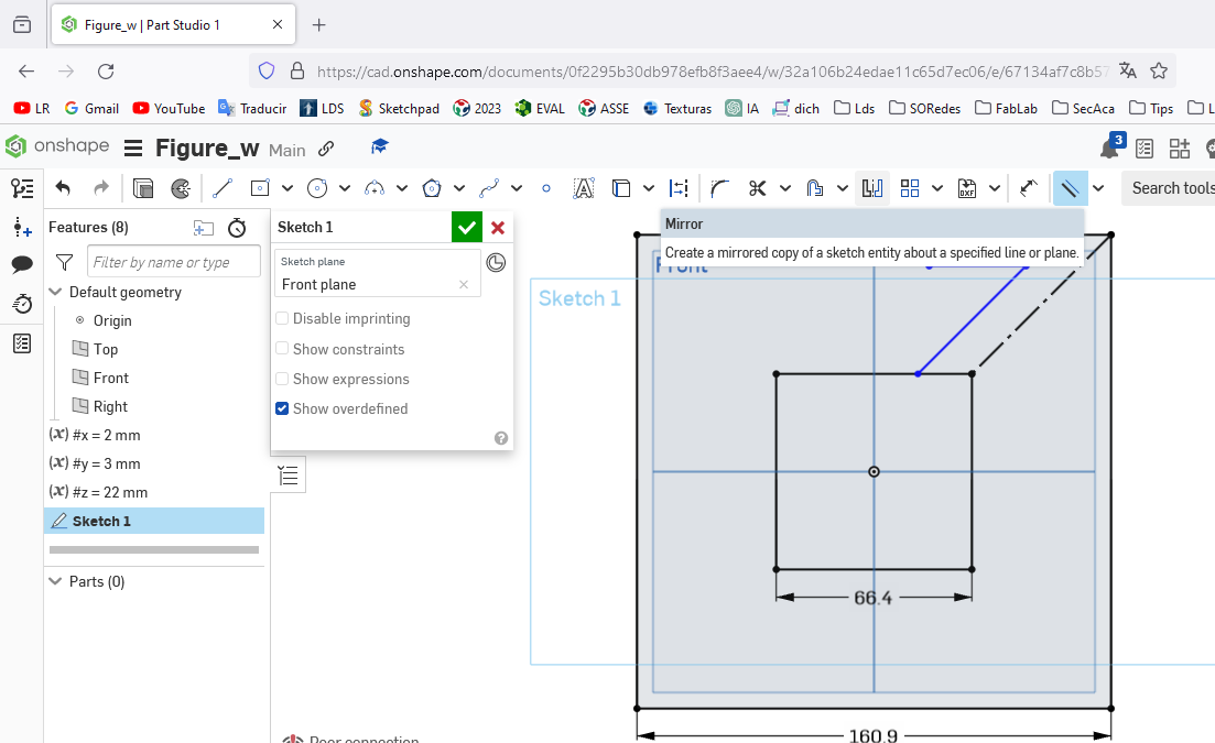
With the blue line drawn, the mirror option was chosen to accurately reflect the drawing.
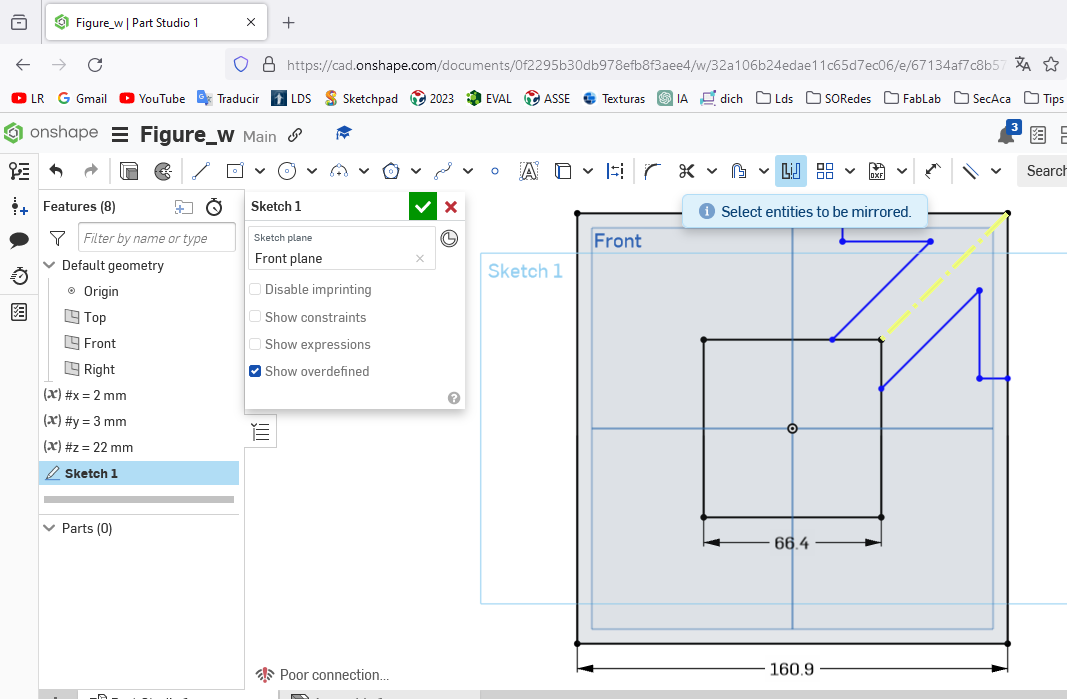
When the mirror option was chosen, the drawing was complete.
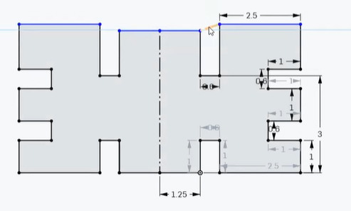
Applying parametric values on the sides of the desired figure.
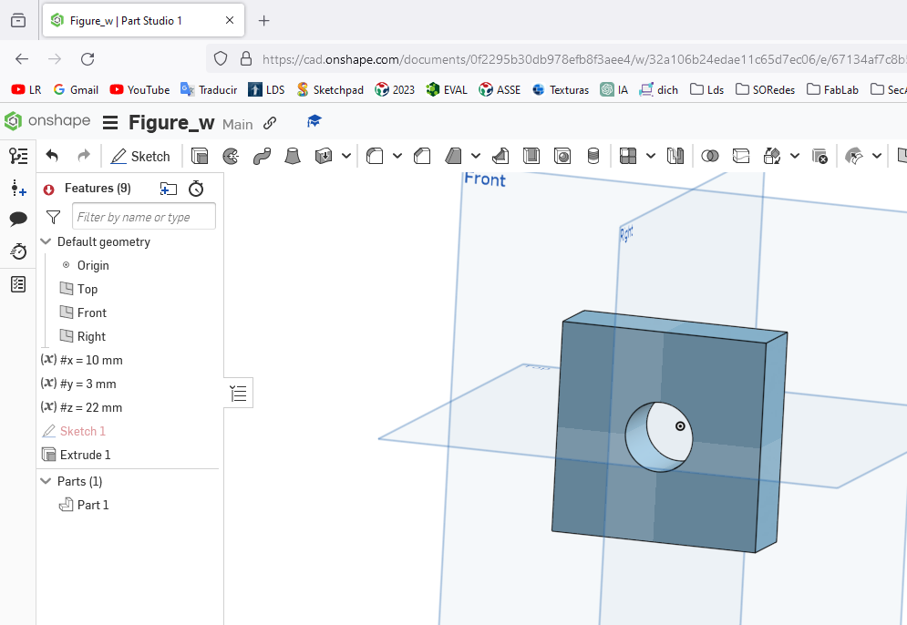 The center figure and the parametric values worked after extruding it
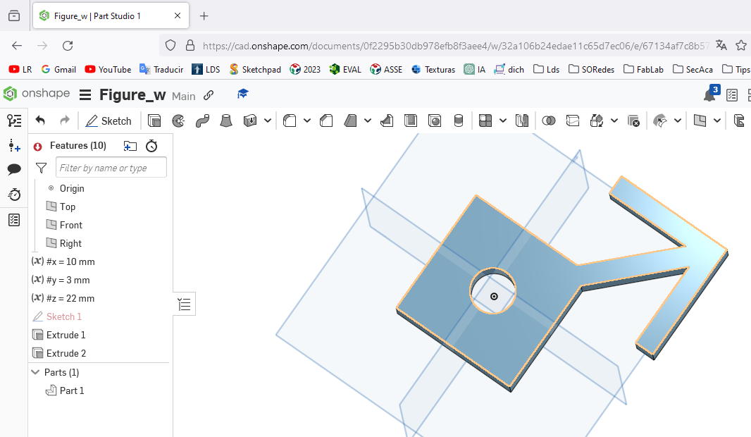 The center figure with the end part designed and extruded.
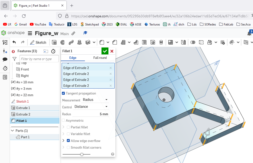 Showing the different edges of the designed and extruded figure
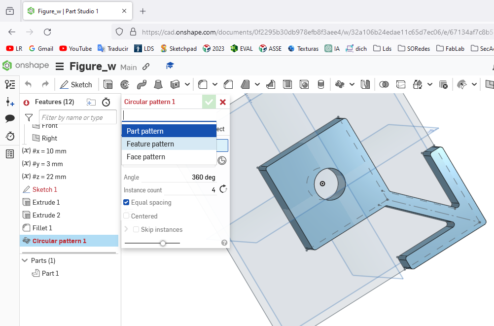
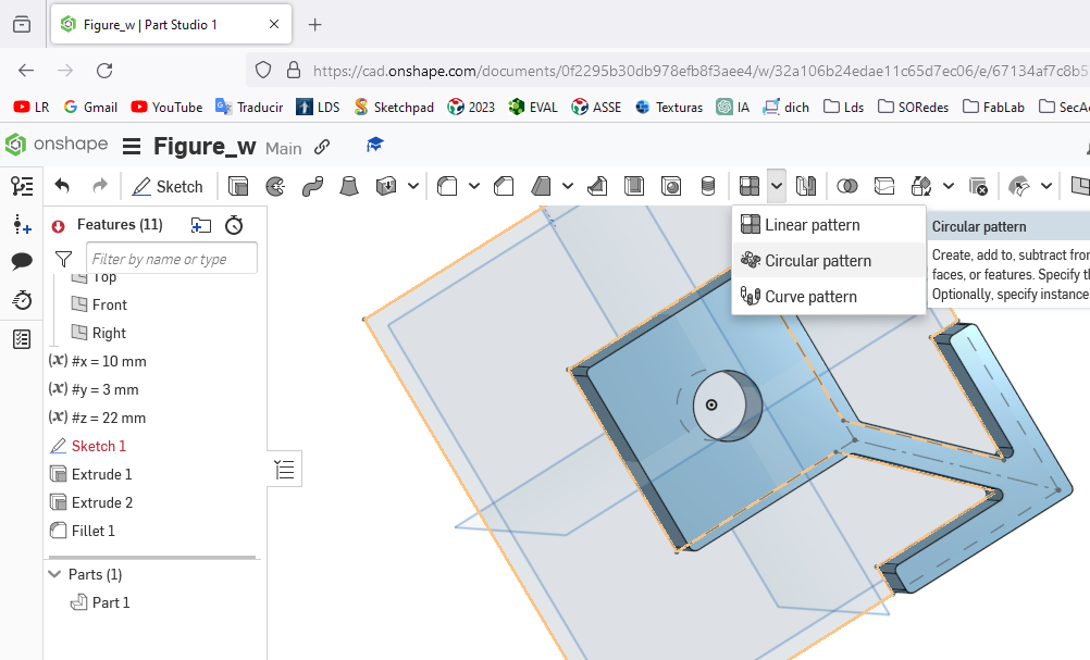 Selecting the design and applying the circular pattern to complete the three vertices.
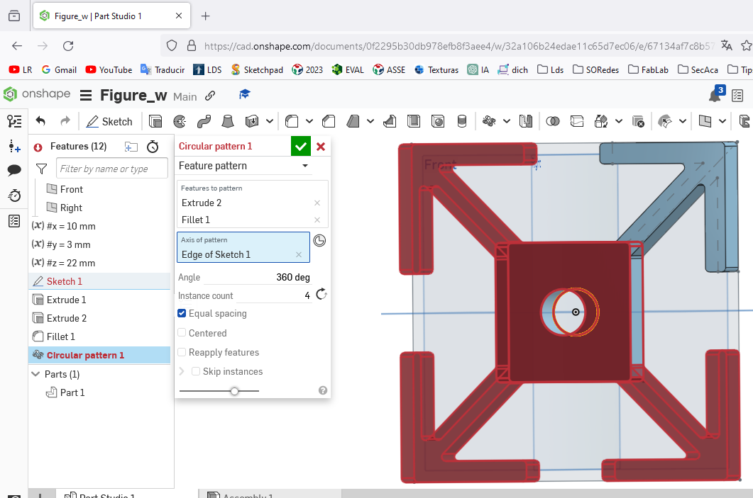
 Applying the circular pattern to complete the four sides in total, completing the turn of three hundred and sixty degrees.
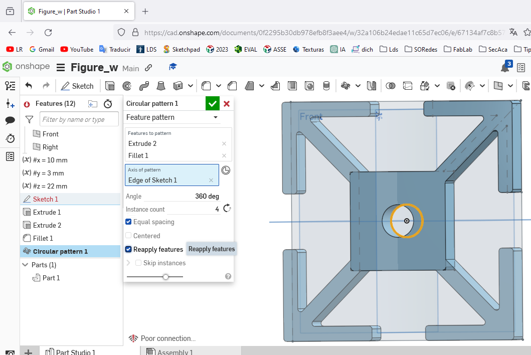
 The figure shows the result of the steps explained above, thus completing the design using circular pattern instructions.
 All this instructions are stored in a new sketch of the onshape program.

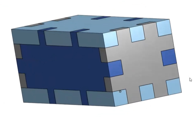
Visualization of the completed design after completing the established steps
 Verifying the parametric values set at the beginning and the representation in the finished design.
 Verification of the spaces on the four sides that will allow it to fit with another figure of the same design.
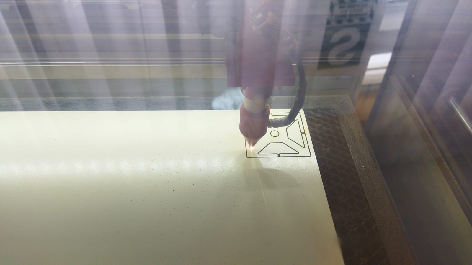 Start of design laser cutting by speed fifteen and power eighty
 Modifying the values since it was not cutting, I increased the power to ninety.
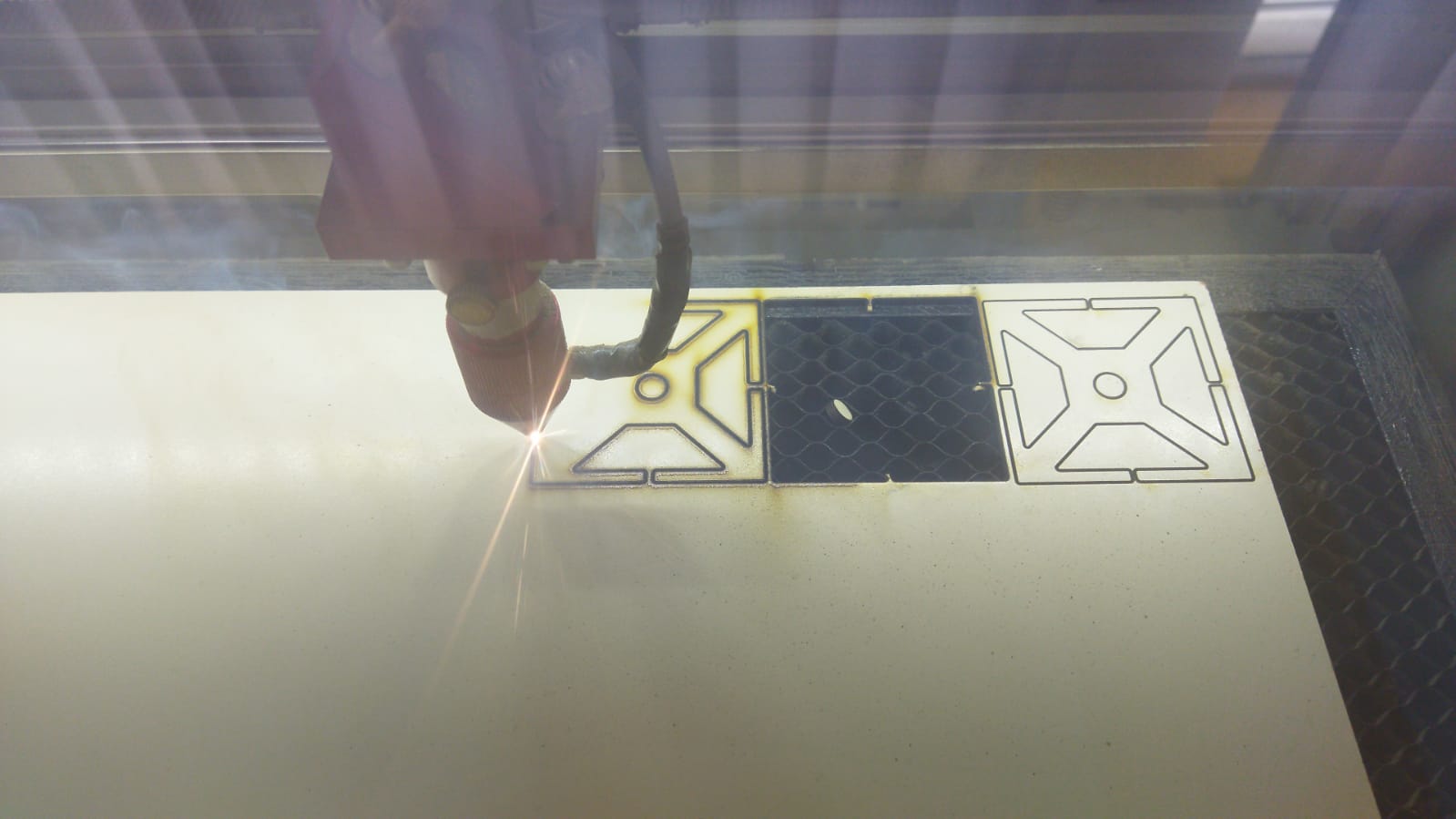
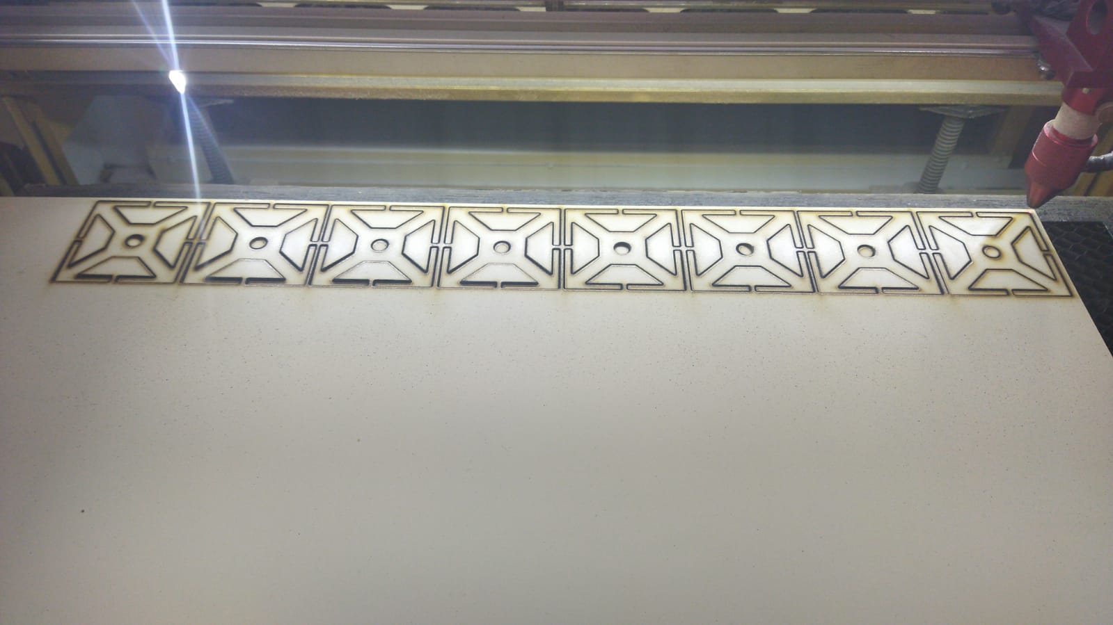 Once the value was modified, we proceeded to continue cutting the other figures.
 After having the cut figures on the desk, they proceeded to join them using the lace that was designed on the edges.
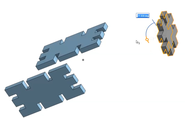
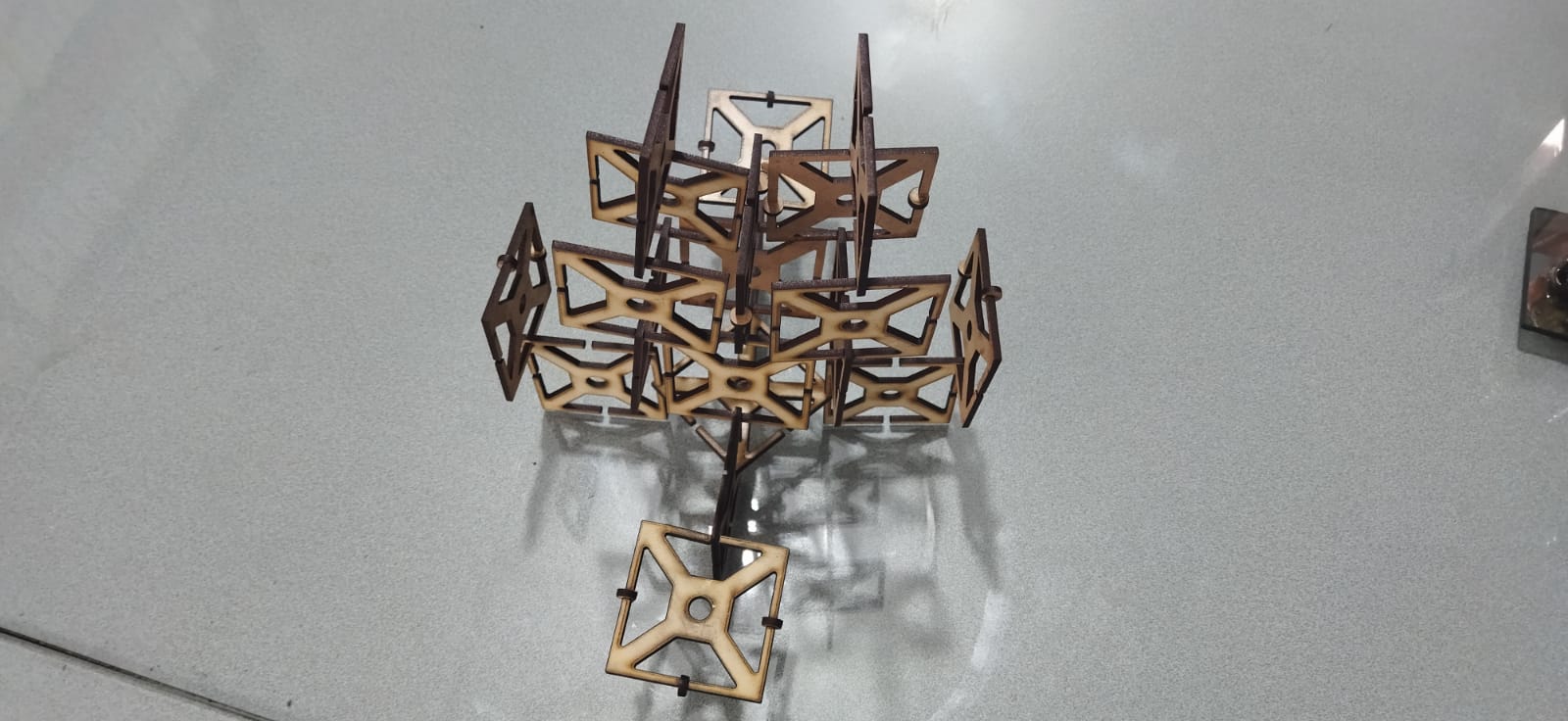
 Using a little imagination, it was assembled to the sides and up.
 The same frame proceeded to modify the angle of fall for the sides.
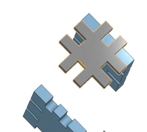
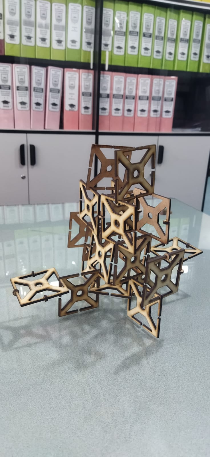
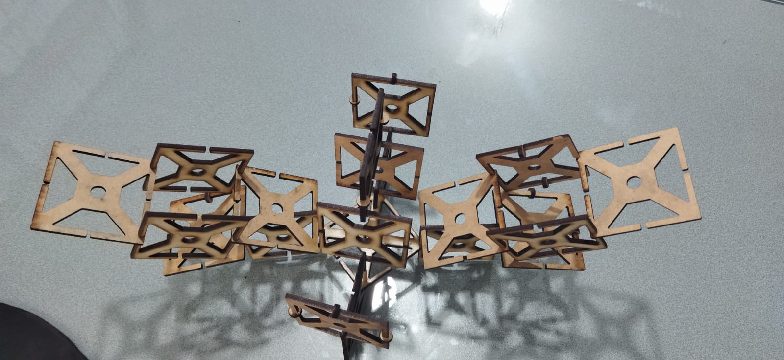 Replicating each piece for the sides over and over again
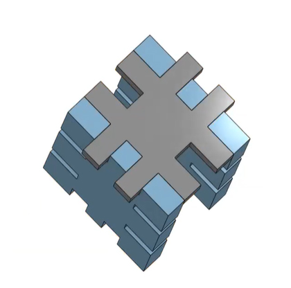
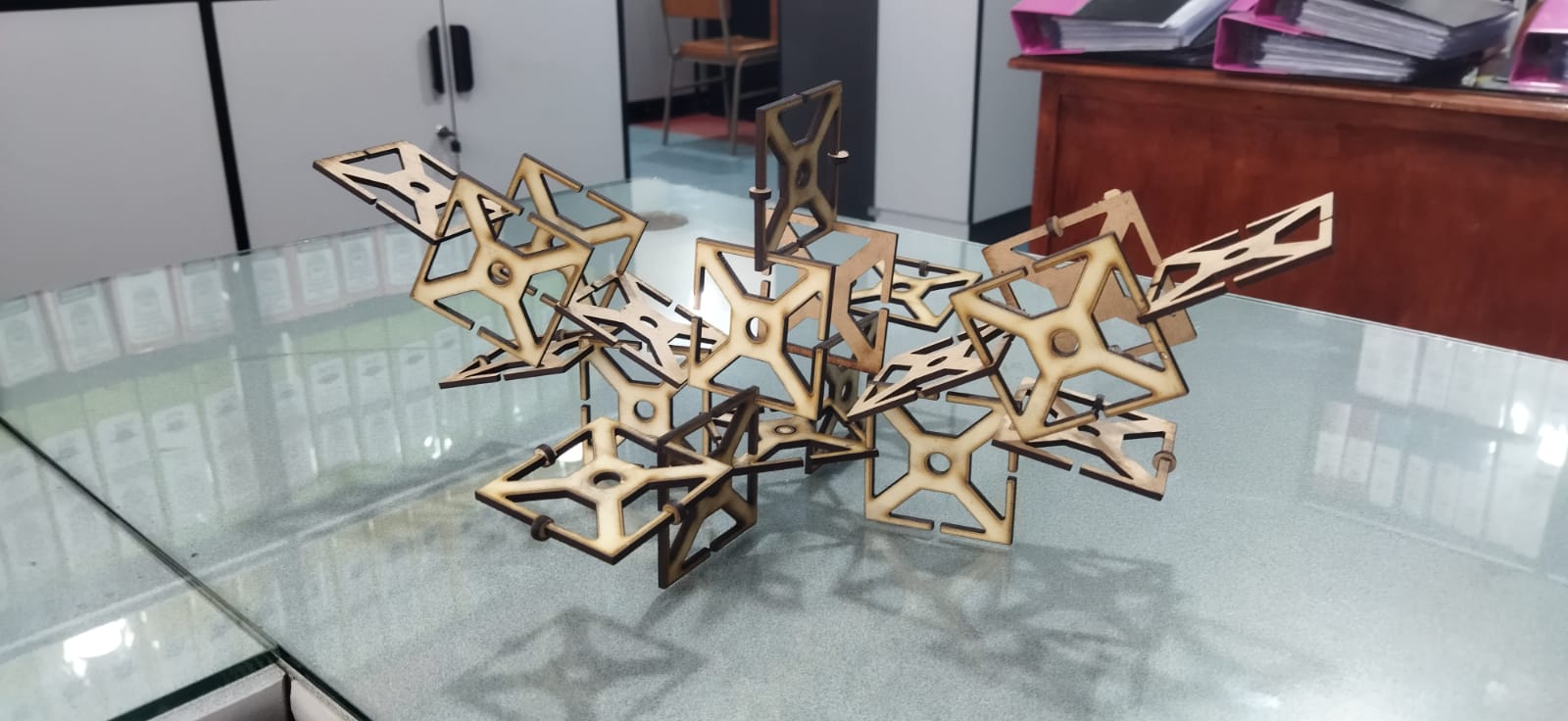 In this way, it was completed in different ways with the established design.
From Youtube
Vinil Cuting Machine.
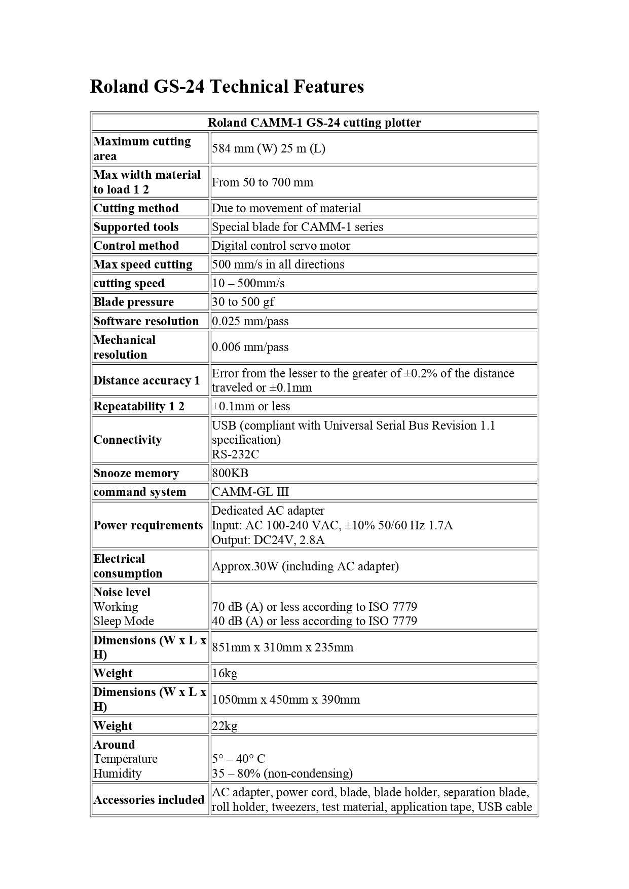
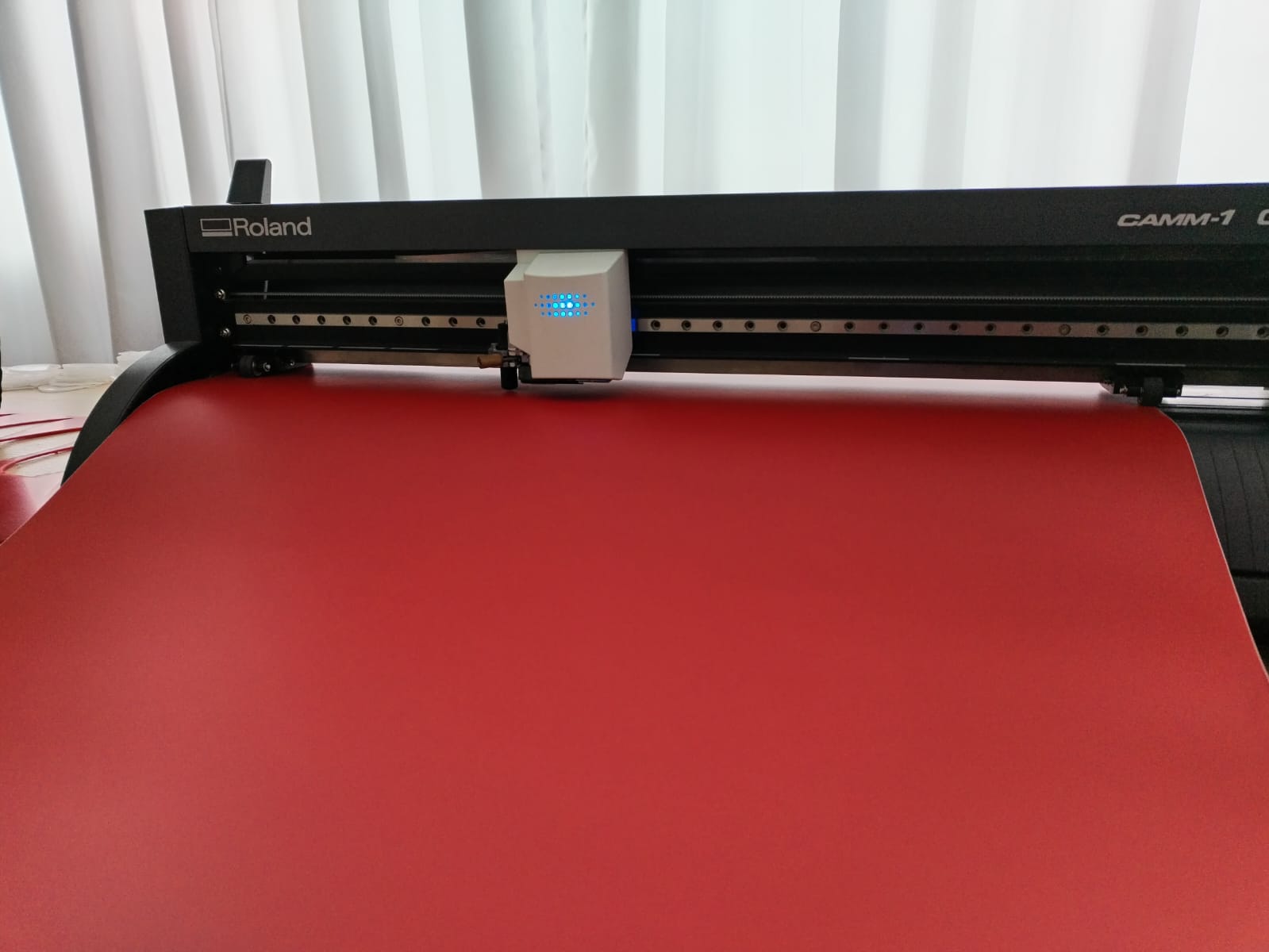
The vinyl cutting work has been carried out with a CAMM-1 Servo GX-24 from ROLAND with the CutStudio design program.
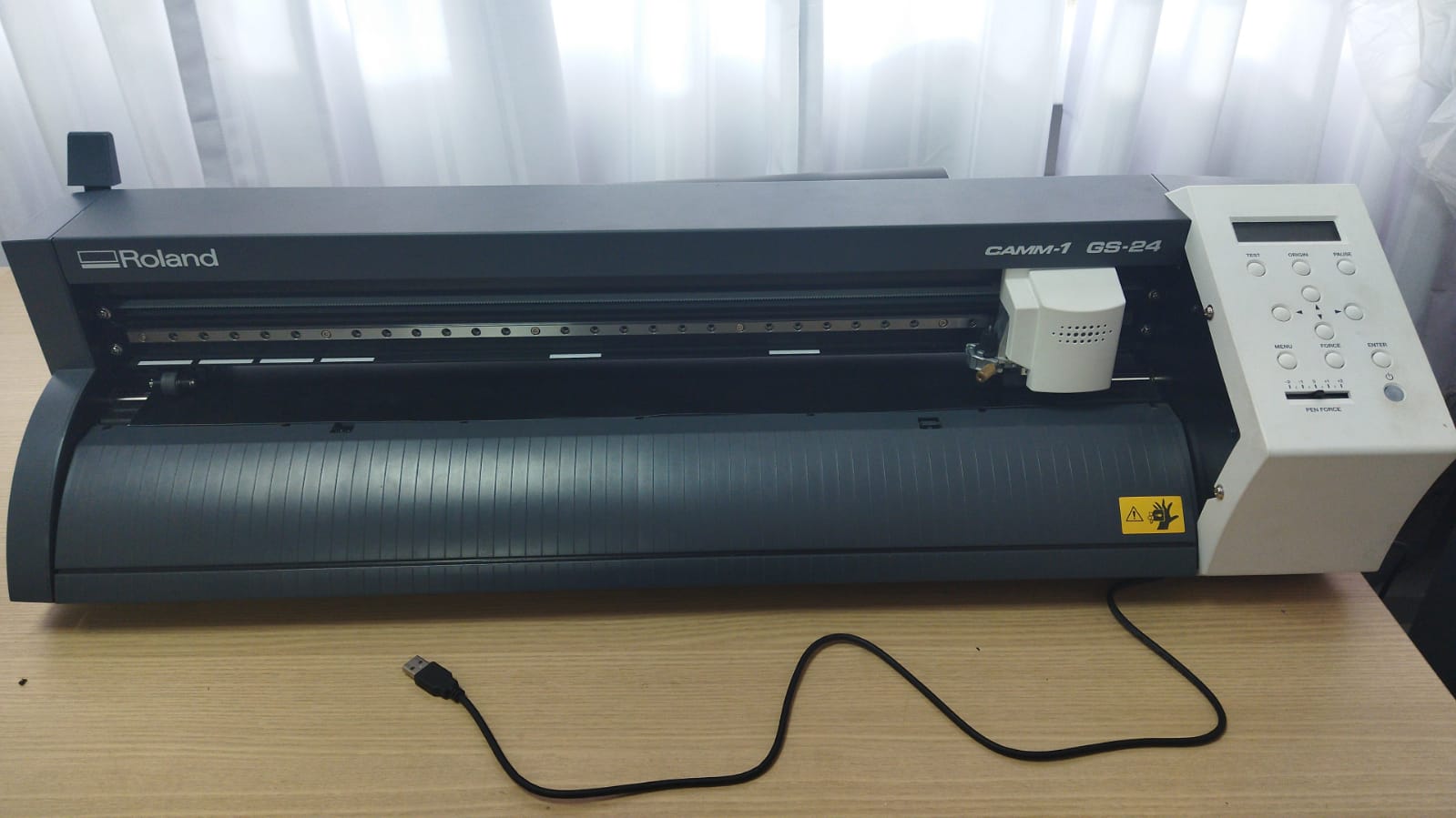 Roland CAMM equipment - 1 GS 24 ready to launch.
 Machine screen once turned on
Roland DG CutStudio
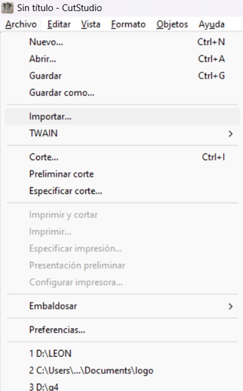
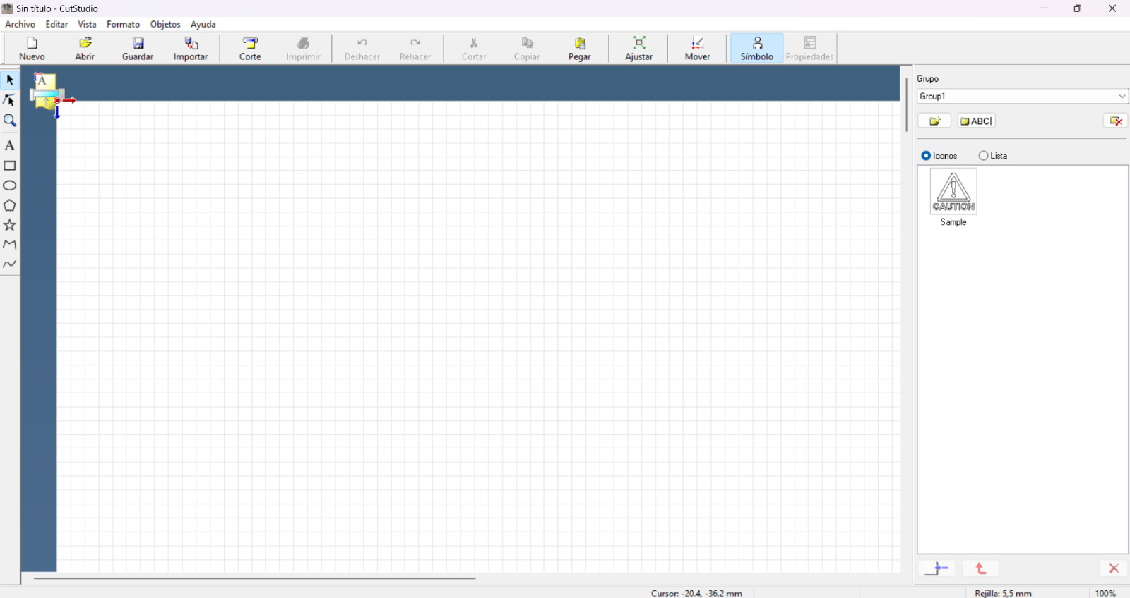 In the CutStudio program, once loaded for file development, first clicking on file then on import and then browse to the chosen file

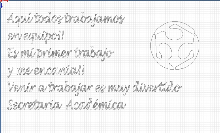
File processed in jpg format ready to be used in the CutStudio program
 Written text that will be processed in the program
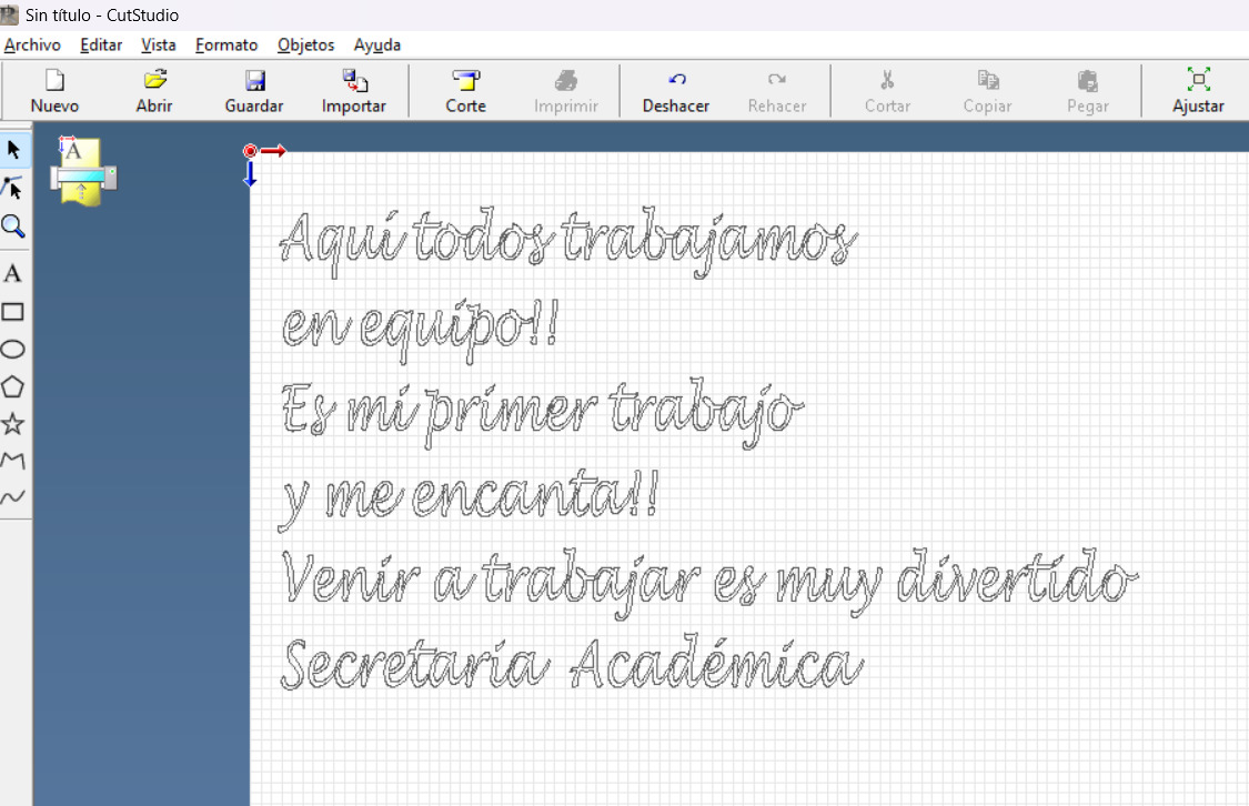 Changed font and text size.
 Process of importing the file worked in jpg into the program
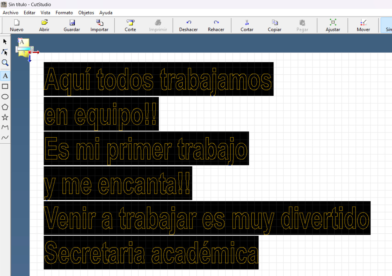
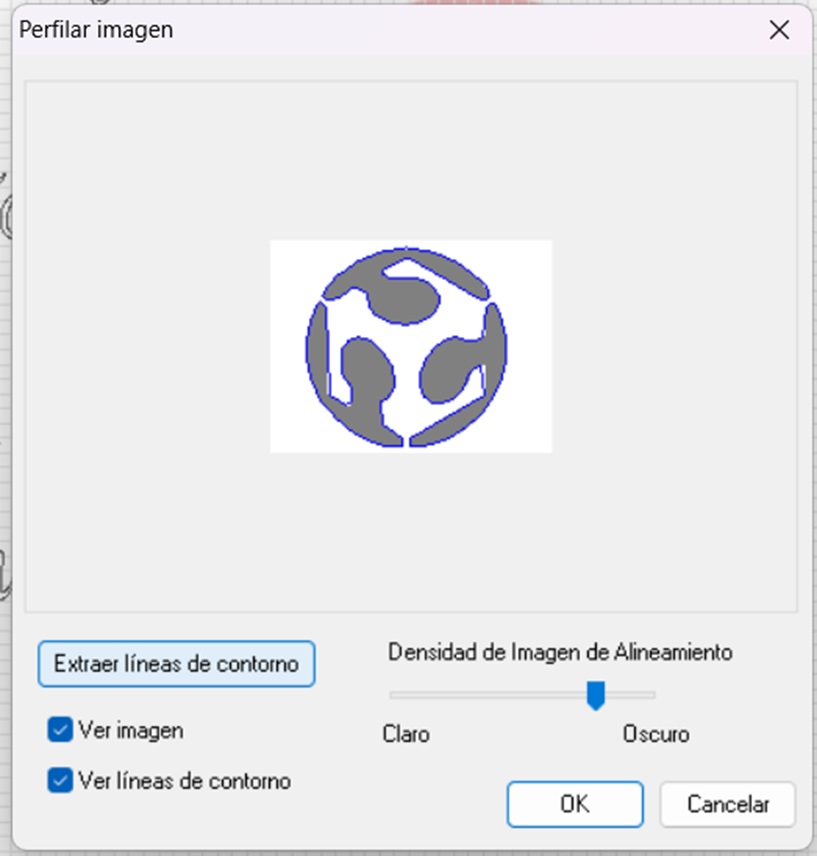 Processing of the imported image by extracting the contour lines
 Image once processed
 Once the first layer of the image is removed, processed in the program.
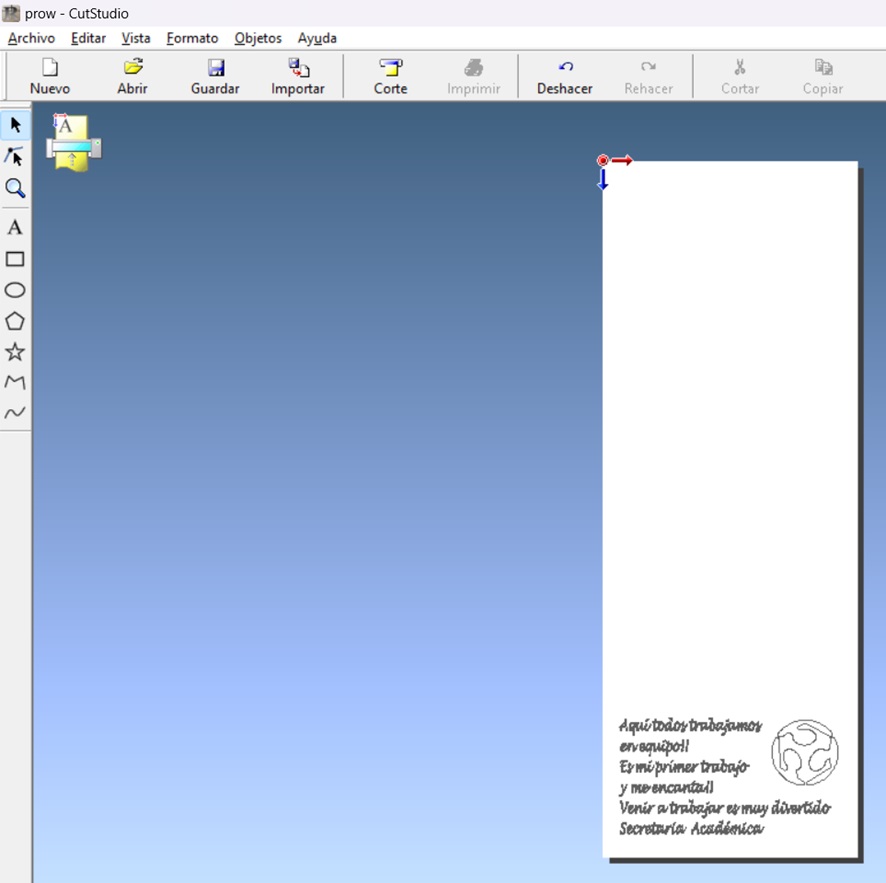 Preview of the printing sheet and the material worked for cutting
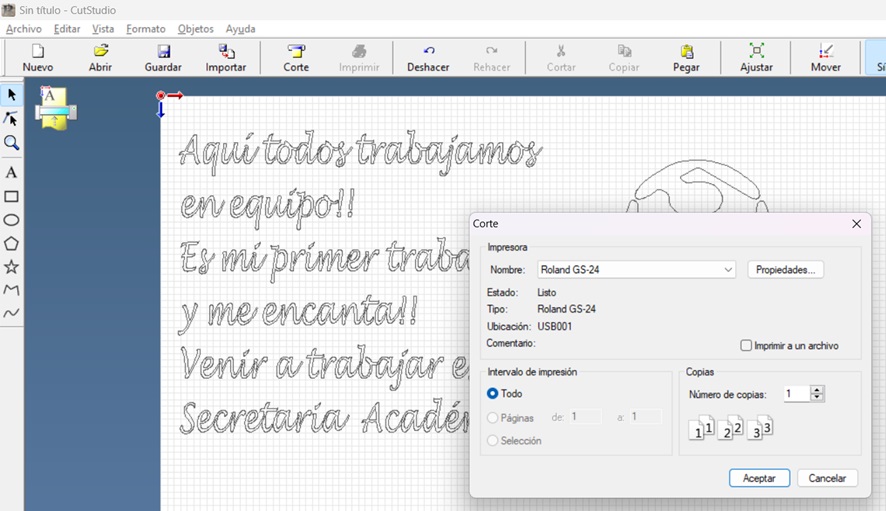 Once the cut option has been chosen, the cutting window is displayed.
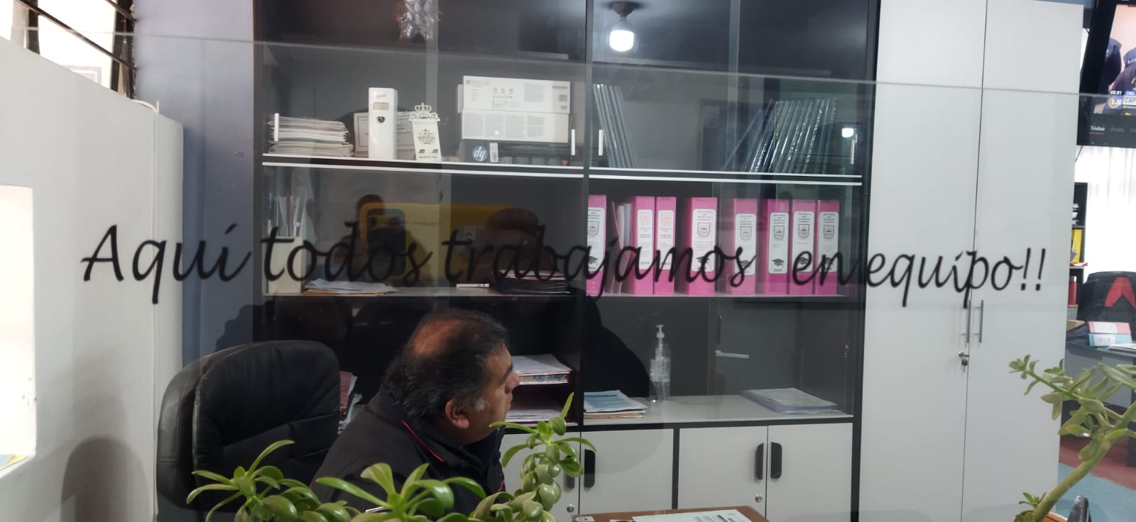 In the academic secretary’s office showing the phrase “Here we all work as a team”
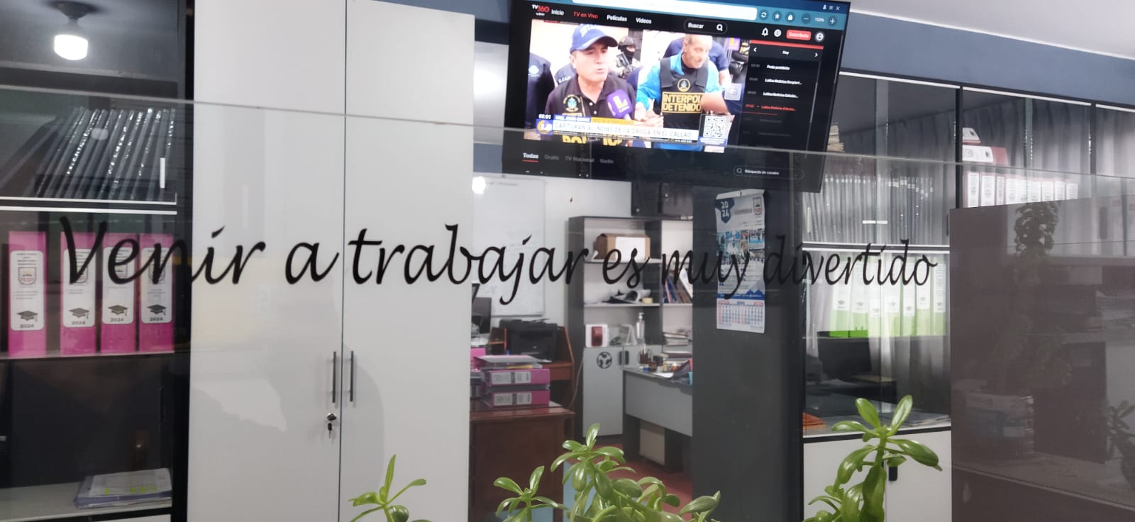 In the academic secretary’s office of the institution it reads “Coming to work is a lot of fun”
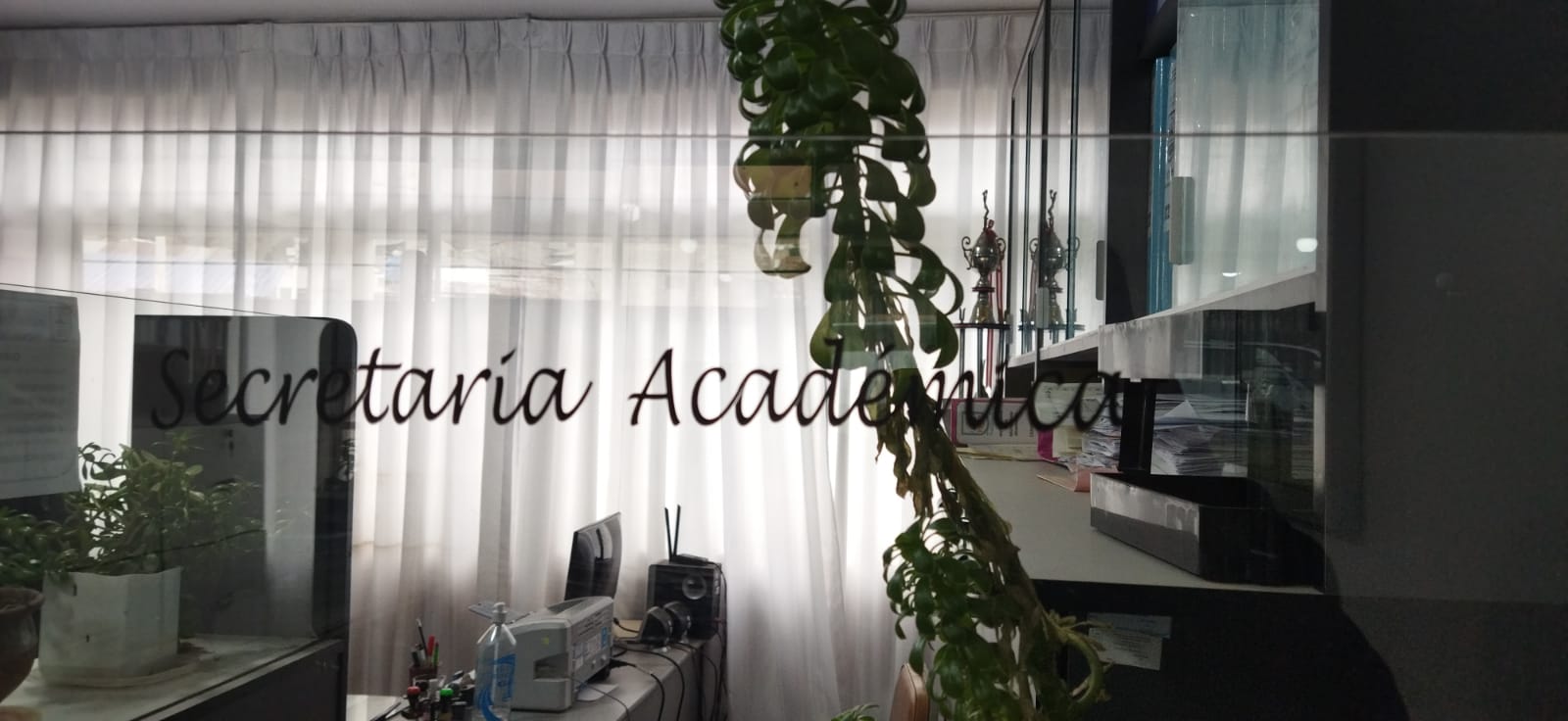 In the academic secretary’s office showing the name
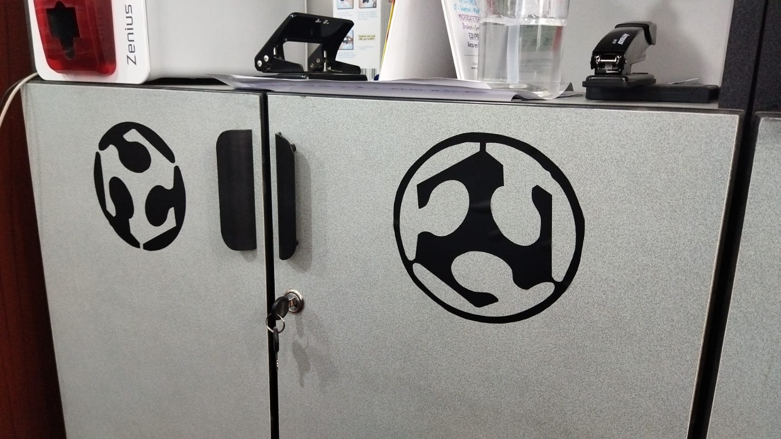 On one of the furniture in the academic secretary’s office you can see the digital manufacturing logo
 In this second process of working with vinyl cutting.
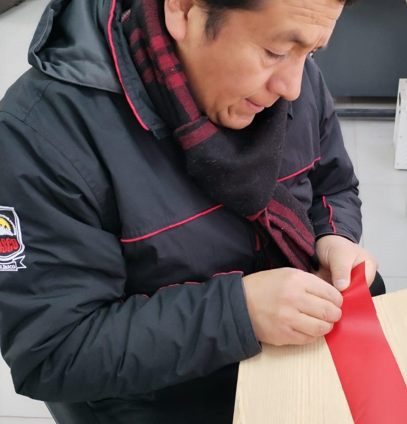 Once the vinyl cutting is finished, check the cuts where the excess must be removed.
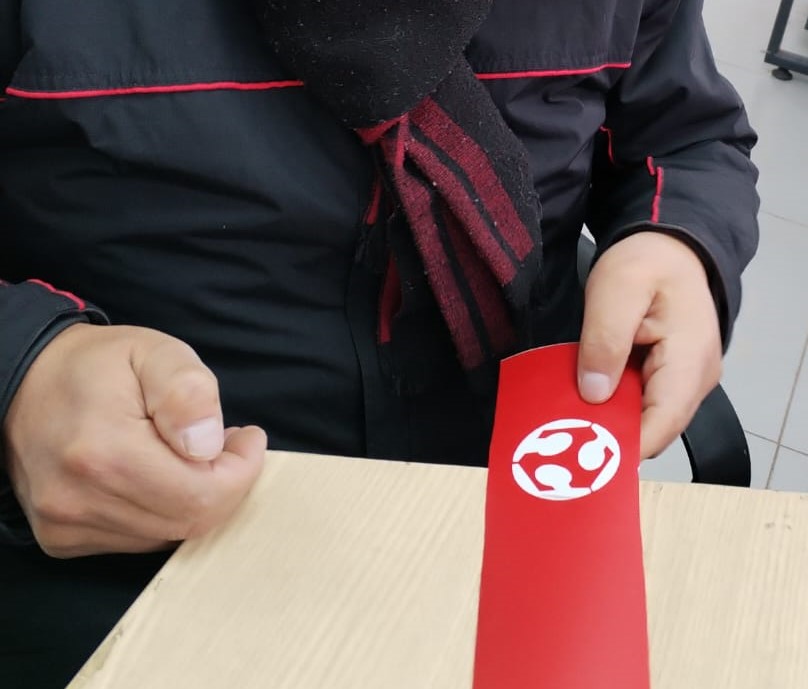 Note after removing the parts that could also be used.
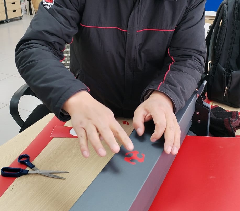
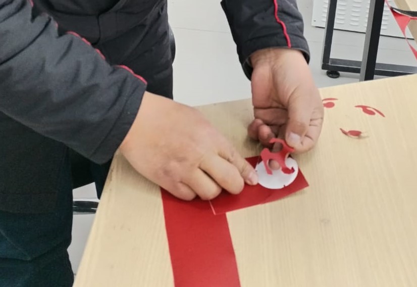 Manually removing the figure to be placed in the destination location.
 Once the gluing is finished on the Roland machine where the cutting was done.