Week 7. Computer Controlled Machining
This week I experimented with computer design to be worked on a CNC machine.
Group assignment:
- Complete your lab’s safety training
- Test runout, alignment, fixturing, speeds, feeds, materials and toolpaths for your machine
- Document your work to the group work page and reflect on your individual page what you learned
Individual assignment:
- Make (design+mill+assemble) something big
Learning Outcomes
- Demonstrate the design of 2D and 3D figures in the onshape program for milling them.
- Show step by step procedures for obtaining cnc production.
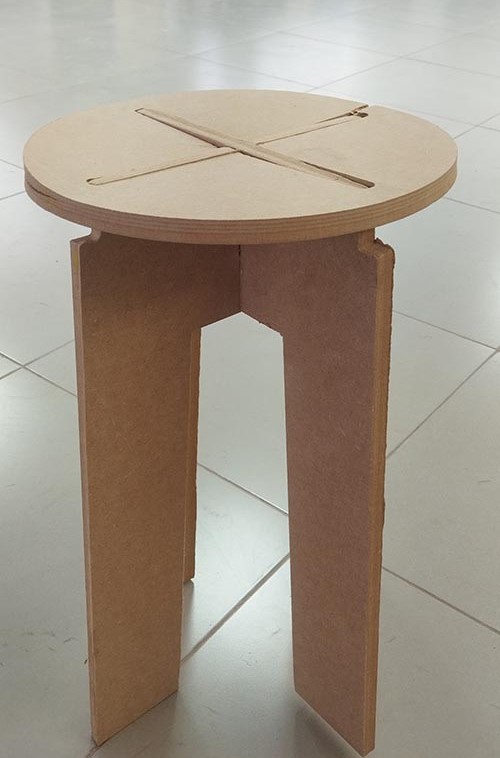
Final result: After manufacturing
I had never designed something like this, I had worked in a carpentry shop but only moving wood, in addition the CNC machine has the characteristic of having a work bed measuring sixty by fifty centimeters. However, the results were achieved.
Links
Group assignment:
As a team effort under the supervision of local and global evaluators, a safety talk was held in a CNC production workshop. View the next LINK
 Obligations and prohibitions signs.
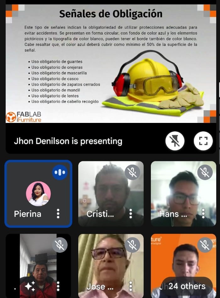 Obligation signs
 Other obligations
 Hearing protection
 head protection
 Eye protection
 How to protect our bodies in the workshop.
 Prohibition signs
 More prohibition
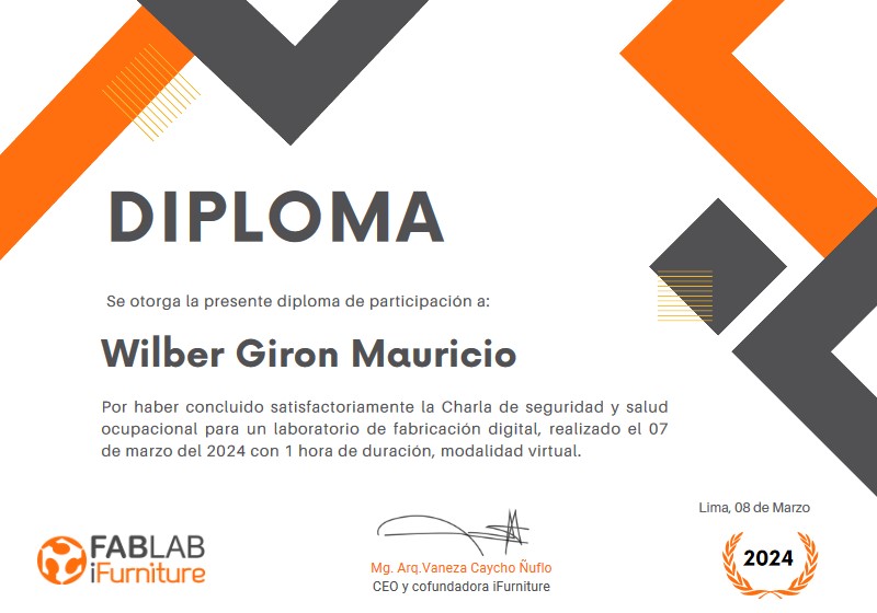 Finally, we obtained a certificate for the training course we took, we have acquired safety experiences in the work environments of a CNC machine.
First steps
Configure cutting process, generating cutting path
- Open the Arcam program.
- Define the width and height of the work area.
- Import vector.
- Import the file designed in onshape.
- Define the starting area from the bottom left
- Select 2d profiling.
- We choose outside and in finish depth we write 16 which means it will cut 16 millimeters.
- We choose the type of milling tool, we refer to the diameter of the milling tool.
- We will indicate the angles that will be inclined when the milling cutter passes.
- We choose the thickness of the material.
- We write the name of our gcode in this case side2 on arrow A and click again on arrow B and verify in the drawing that appears in its outline a lilac image that means that the cut will be made through that route as shown.
- We choose to save the file.
- We continue exporting the file by pressing the arrow.
- We choose the gcode with tap extension and choose which folder to export.
- We run the Nomad Panel software and import the file
- The file is verified for cutting with Red Fox CNC
- We choose the starting point of the cut for which we give 0 to the X, Y, Z axes and make start to start the cut.
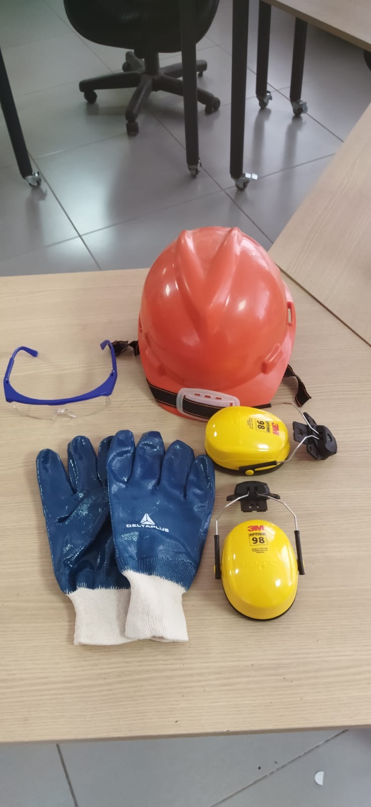 Preparing safety equipment in the work area.
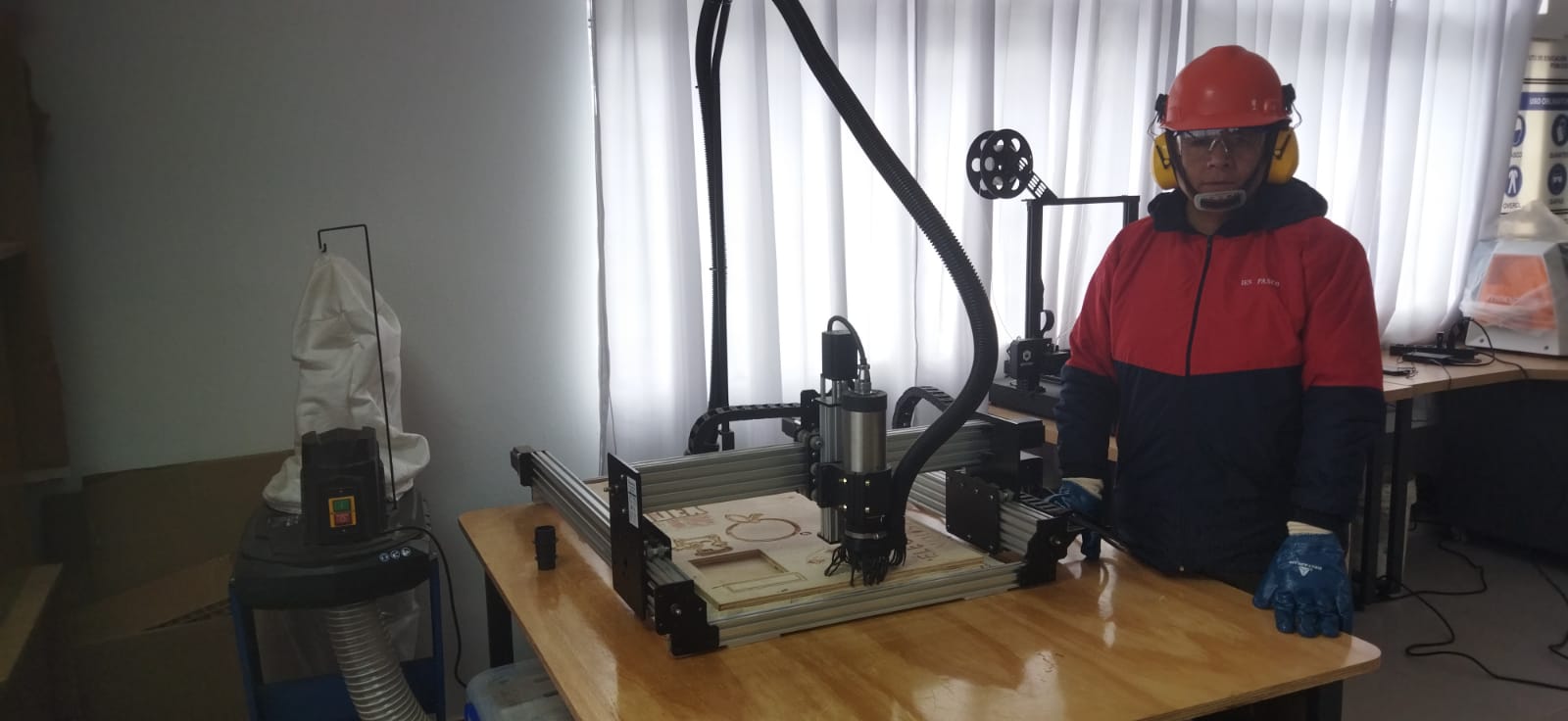 Already with the respective protection for safety
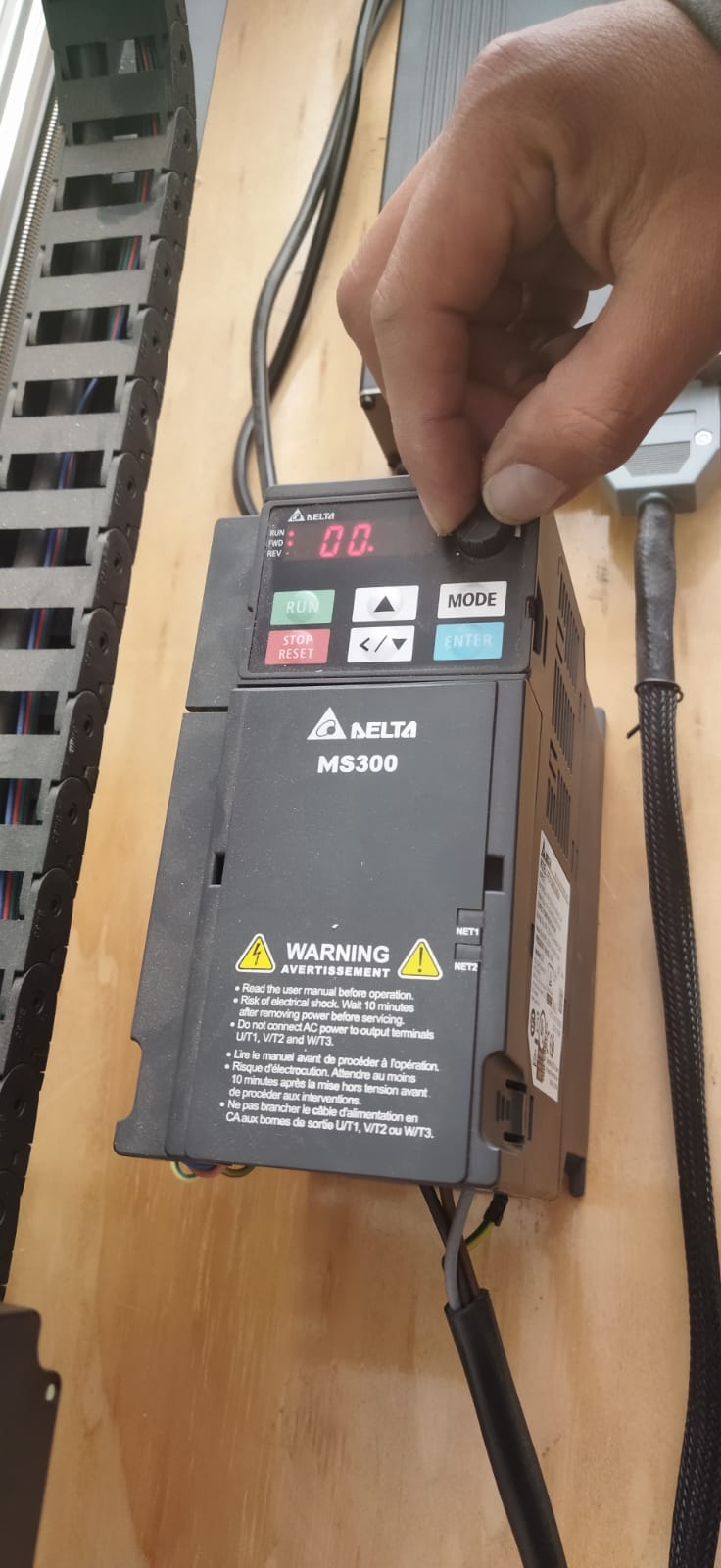
 Turning on the equipment
 Showing revolutions per minute control initializing from zero
 After starting with the green button, begin to increase the revolutions of the bur.
 Increasing the revolutions of the cutter
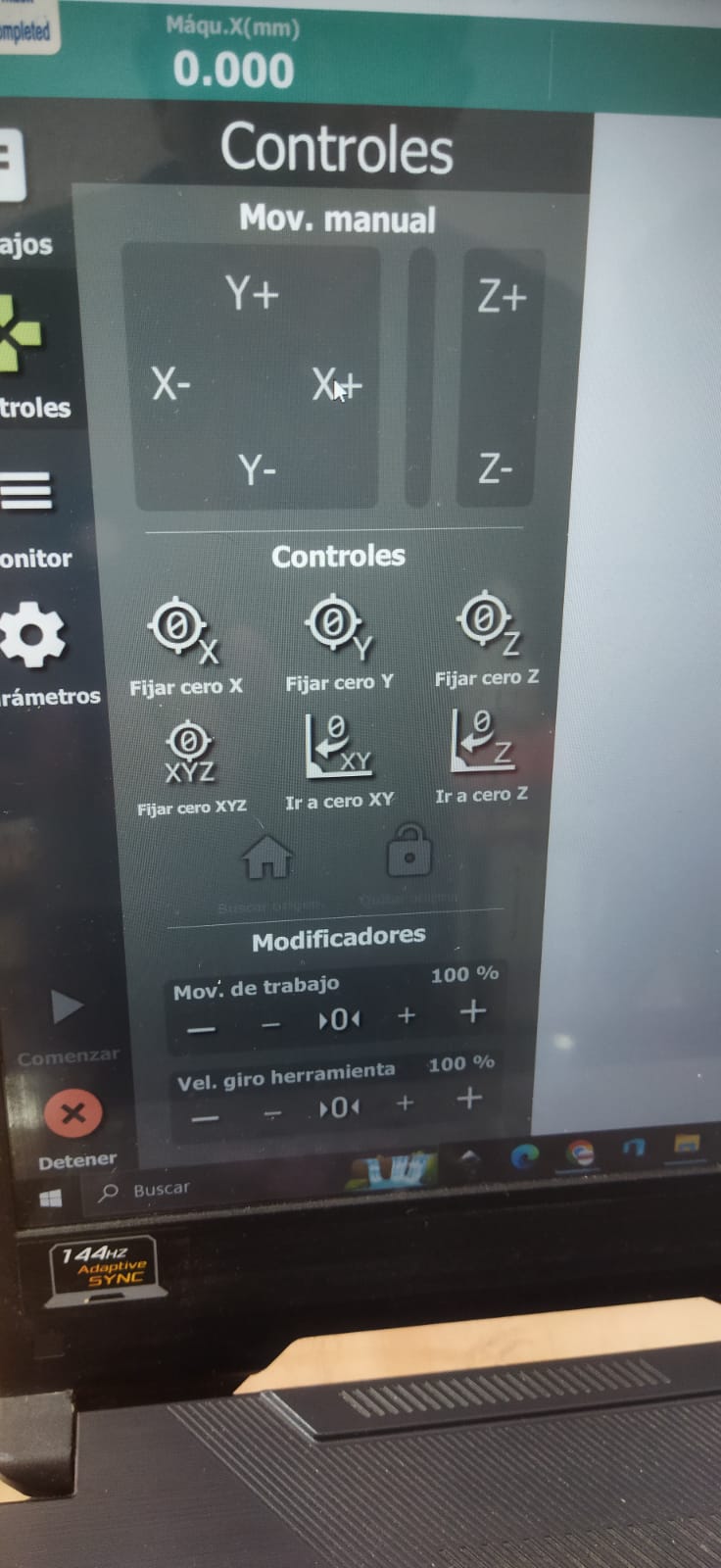 From the computer calibrating and setting the three initial axes whether x, y, z
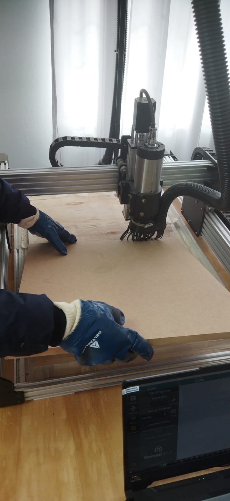 Placing the work material, in this case mdf. Our work area has a 50 by 70 cm work area division and there we put the 15 mm thick MDF, fixing it to the bed by nailing the edges so that our material does not move.
 Taking out the milling tool.
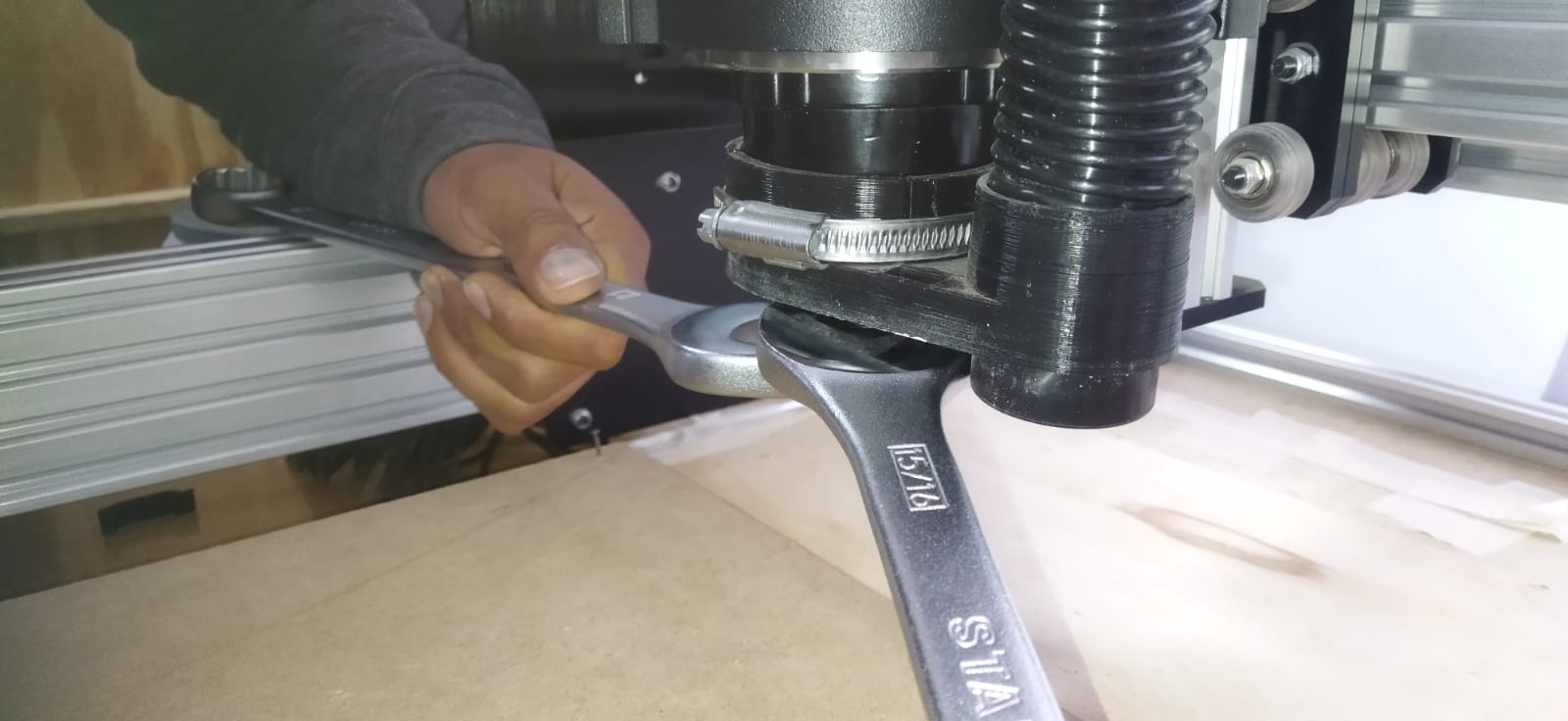
 Placing the corresponding milling tool. The 1/4” diameter, 3/4” cut length, up-cut spiral mill.
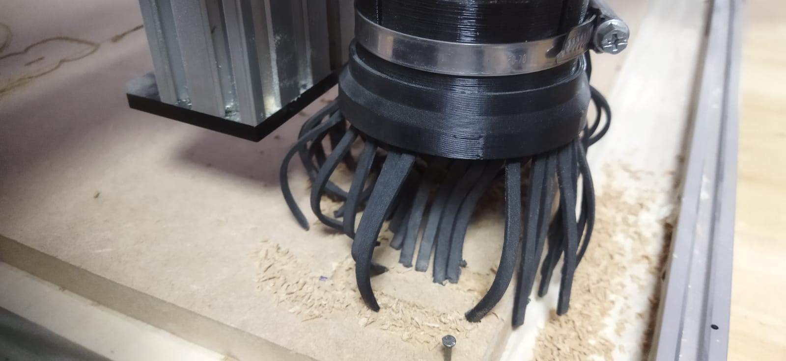
 Placing the protector to avoid watering the bit of material that is going to come out
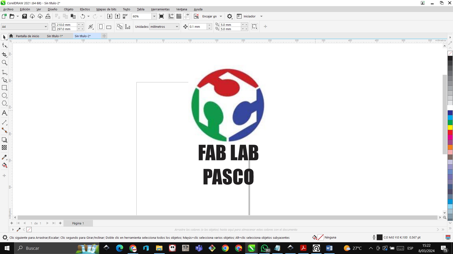 First we import an image into the inkscape program
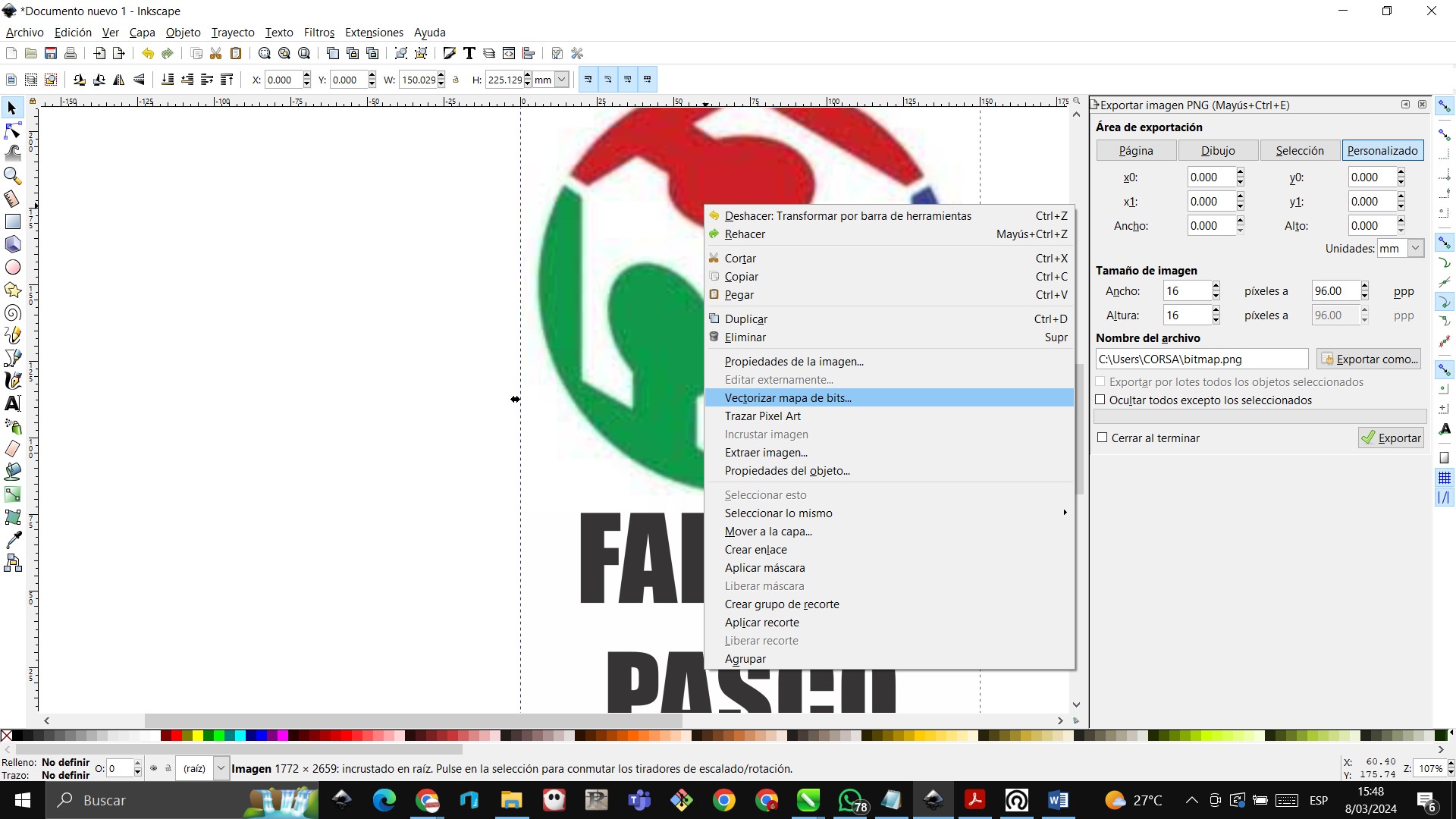 Then vectorize the image in the detailed program
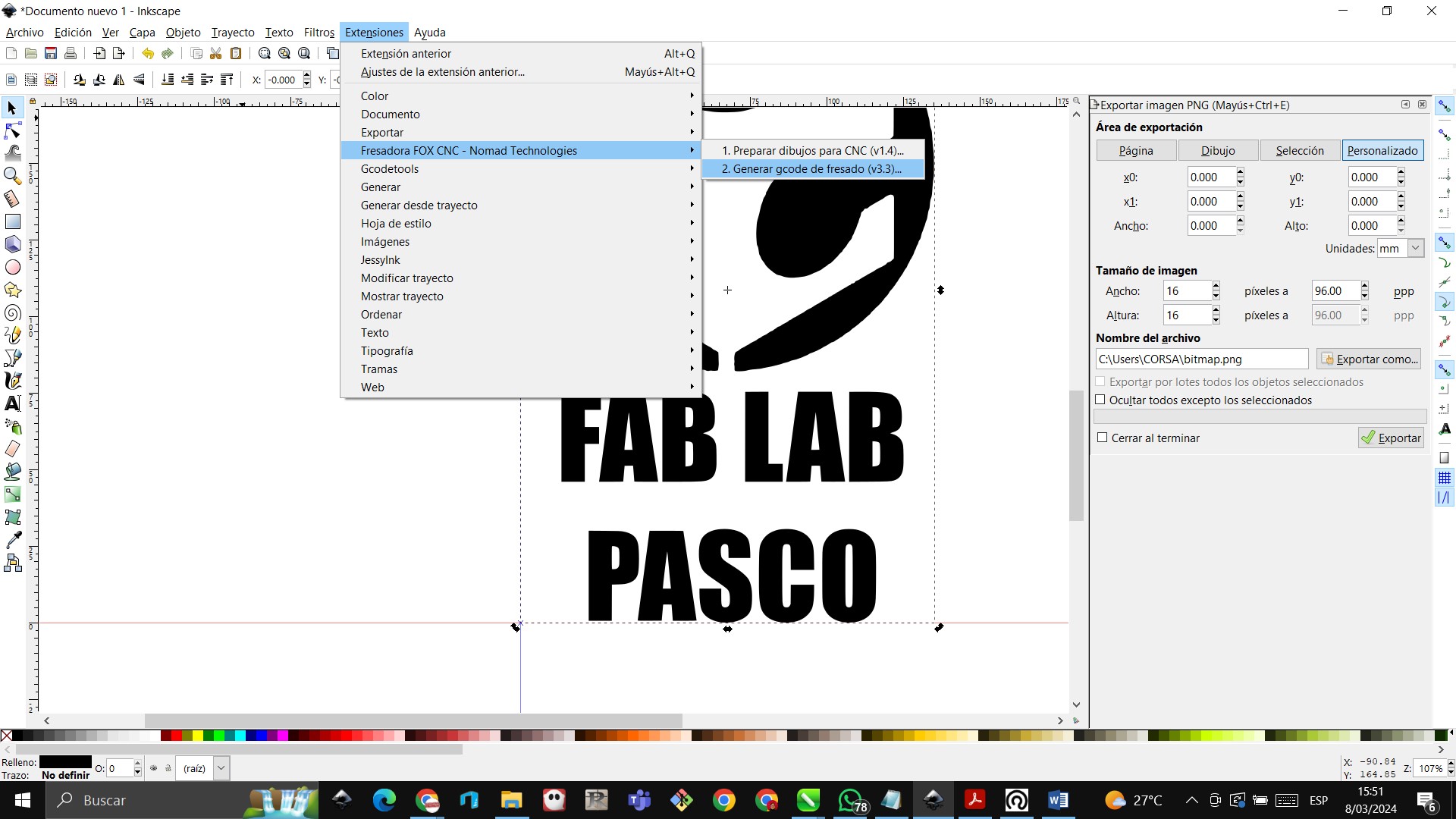 From the extensions menu, we choose the milling machine and then generate milling gcode
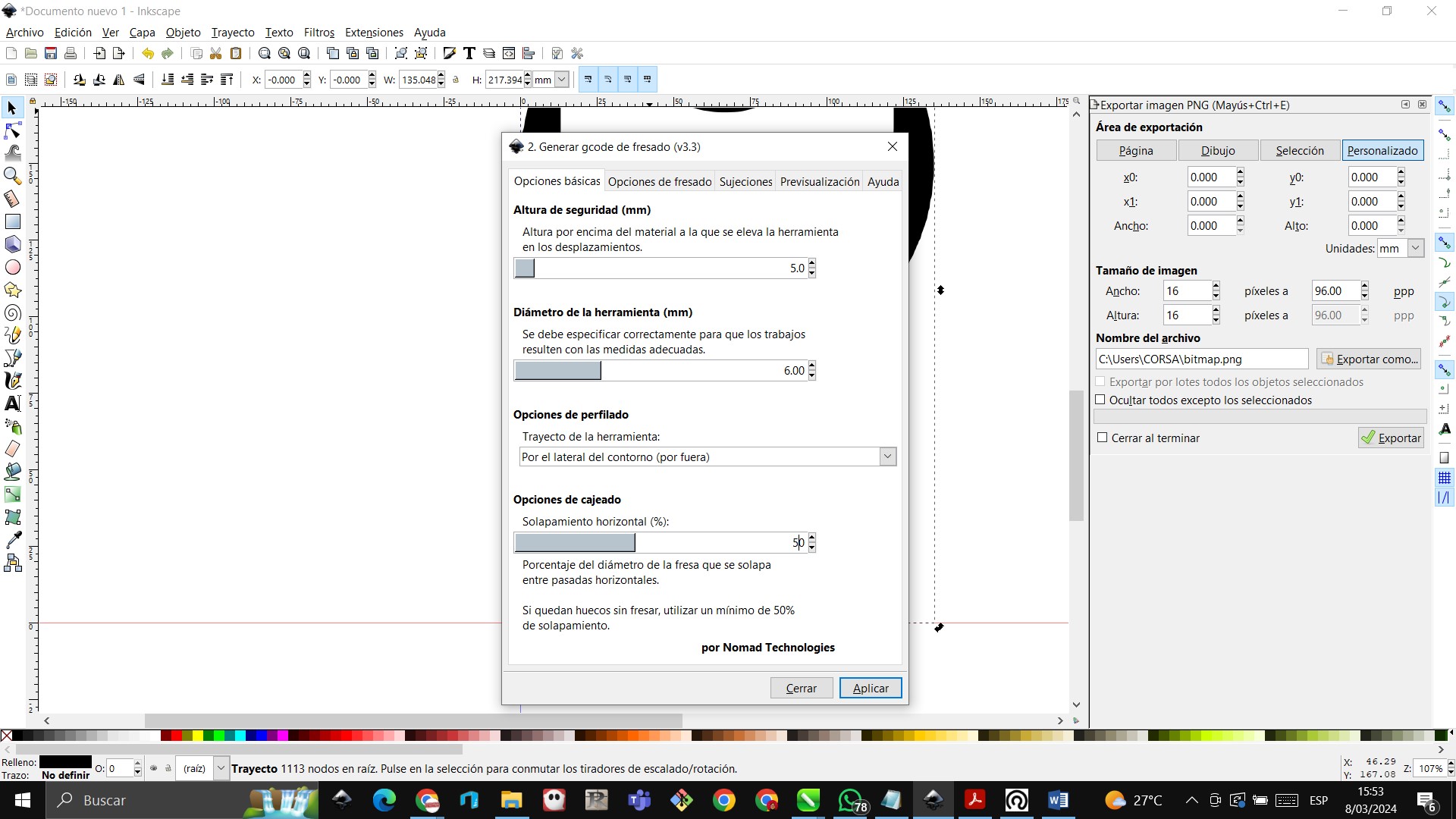 We choose for this first case the gcode settings as shown in the image.
 Already in the process of milling a design.
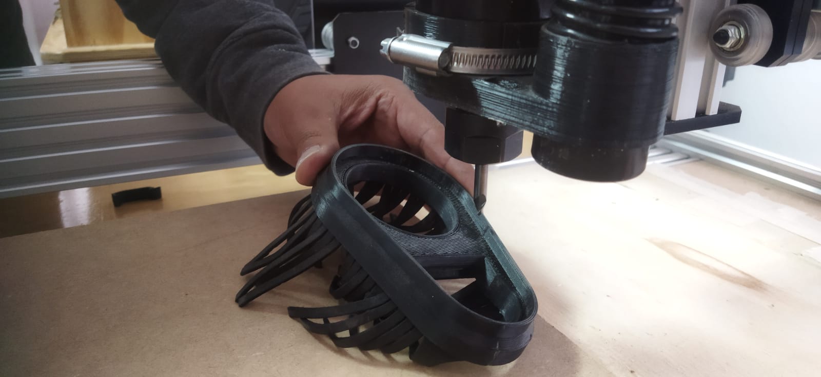
 The first milling result learning the depth settings.
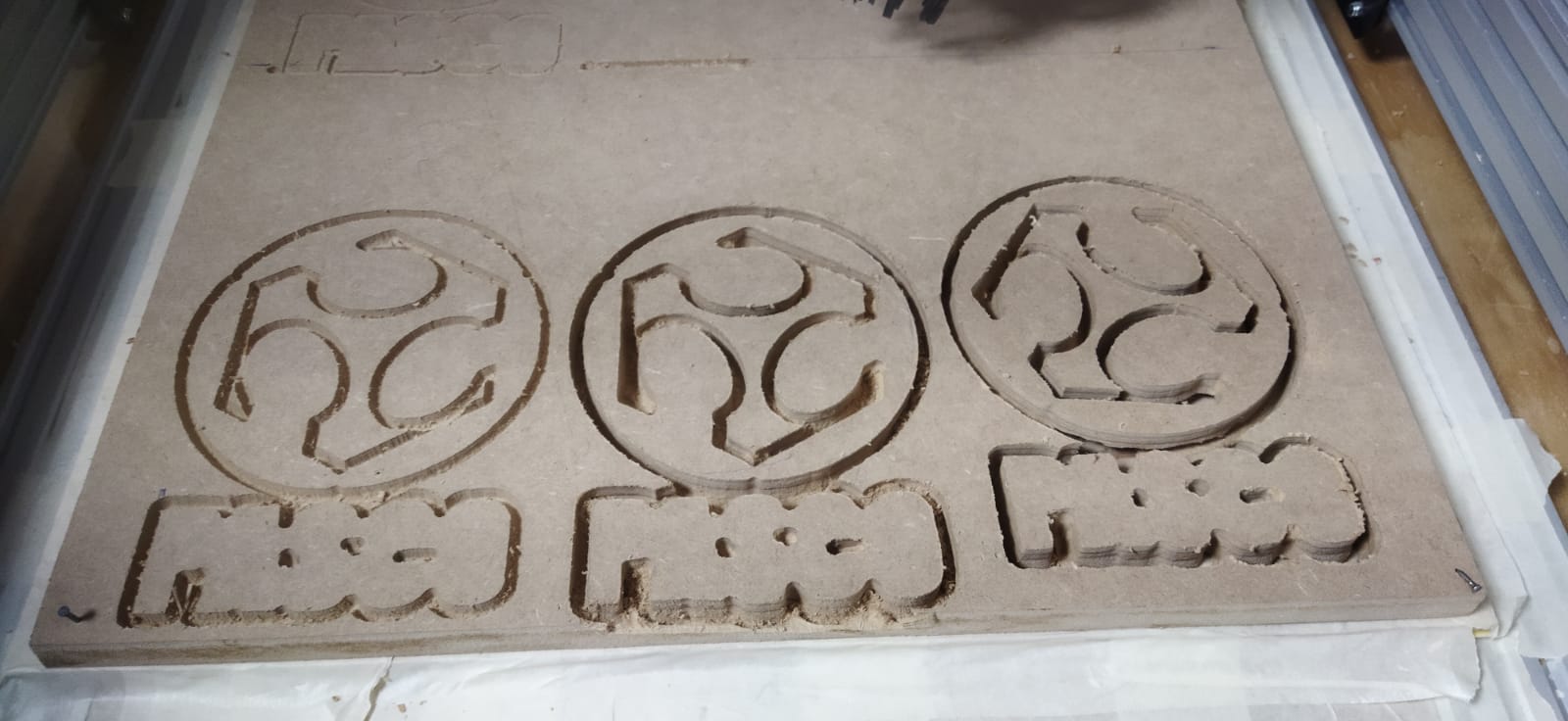 The three milling tests with different depths of the model.
Design
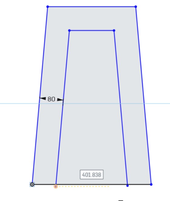
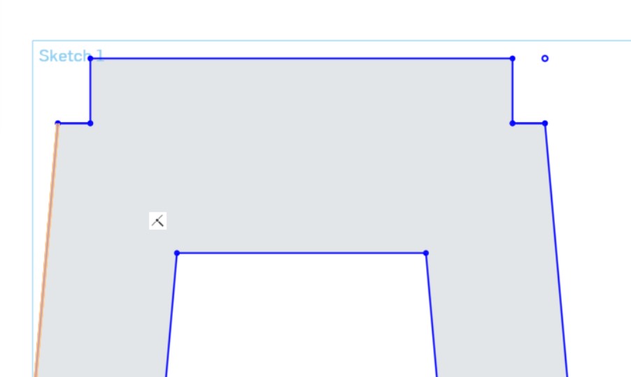
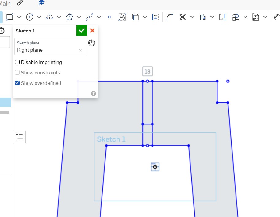
 In this first image in sketch 1, with the line tool, we are beginning to draw the final product, which would be a stool.

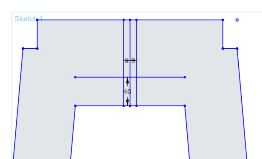
In the following image, specific values are being given for the size of the design.
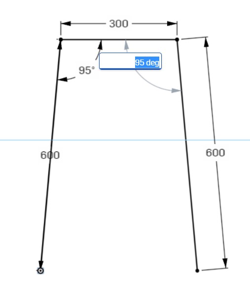
Then you are assigning the inside tilt angles.

Using offset we make an image inside the drawing.
Then we insert a horizontal line at the bottom as shown.
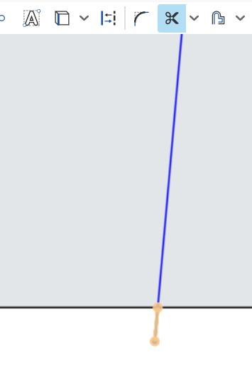
Then with the trim tool we remove the excess part.
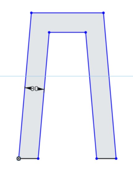
Then we eliminate what is left over so that it is as follows.

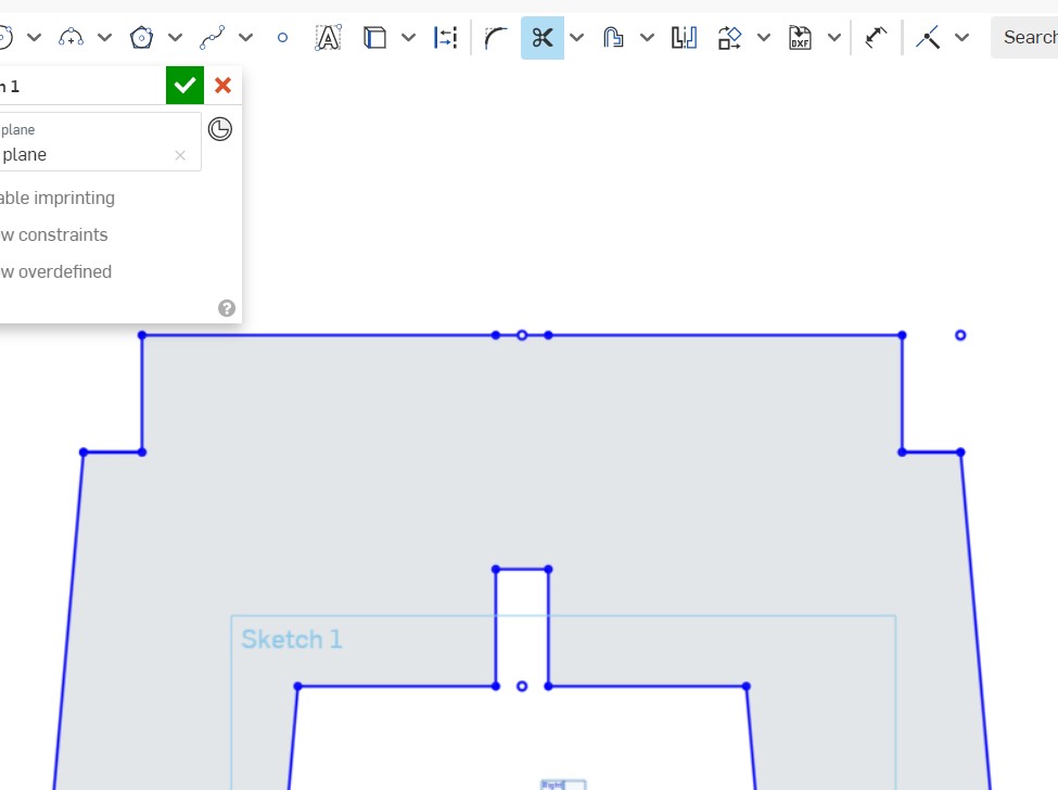
Then we draw a rectangle at the top with the measurements shown.
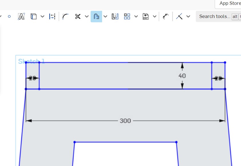
We draw with offset on both sides.
Then we eliminate the remaining parts to be as follows.
In the next step we continue drawing with offset in the middle part.
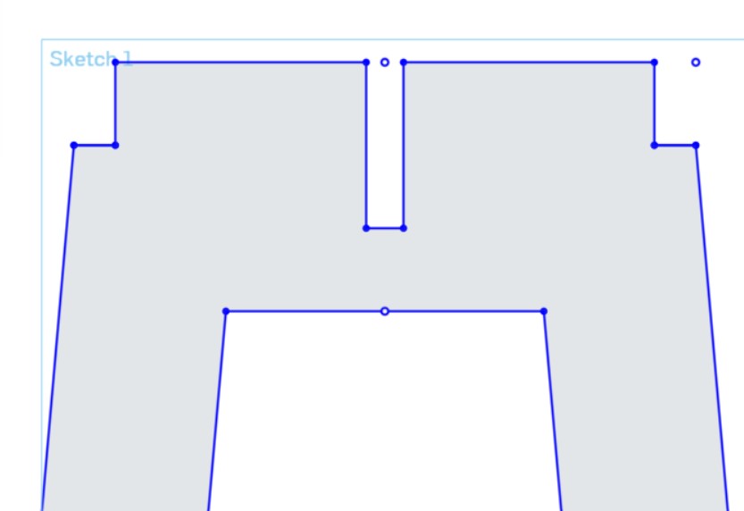
Then we delete the middle part so that the design is as follows.
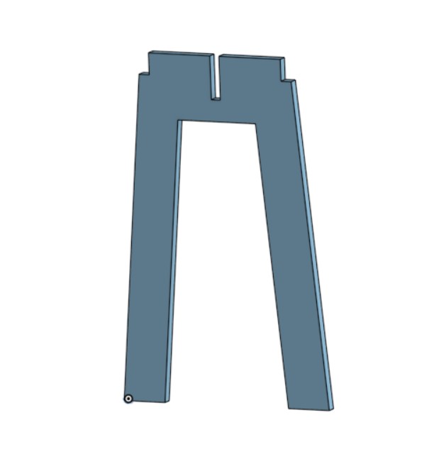
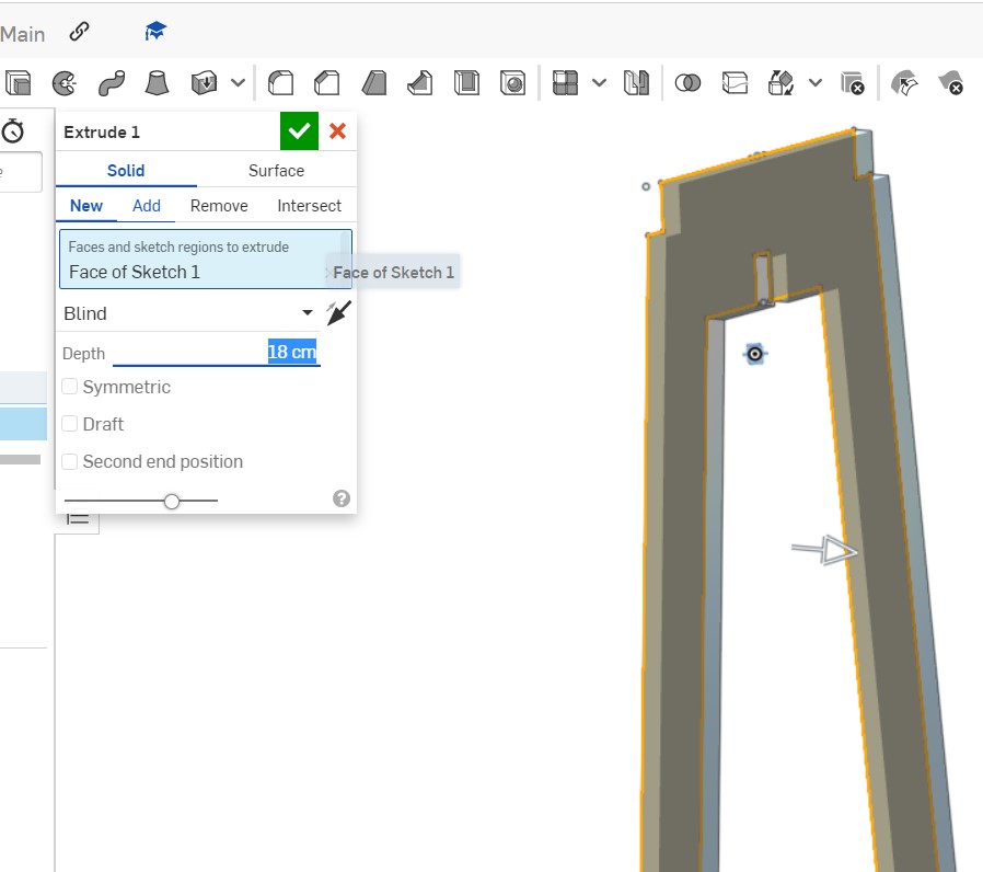
Then we extrude the figure.
In this figure it can be seen that we duplicated the previous figure and then modified the middle part for the fit.
Part of the design is removed so that the lace remains as shown
Then we extrude the second shape that will fit the first
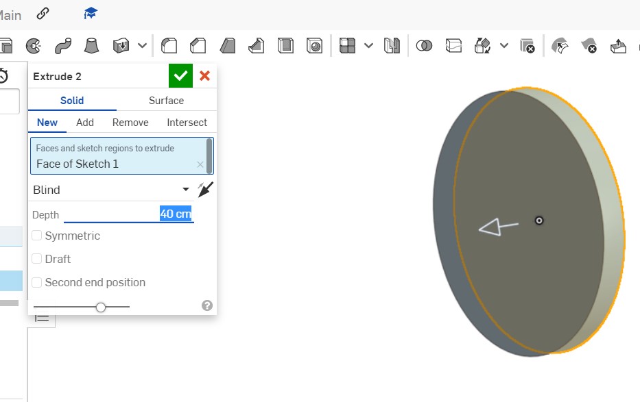
We design the third figure that is going to be part of the seat and then we extrude it.
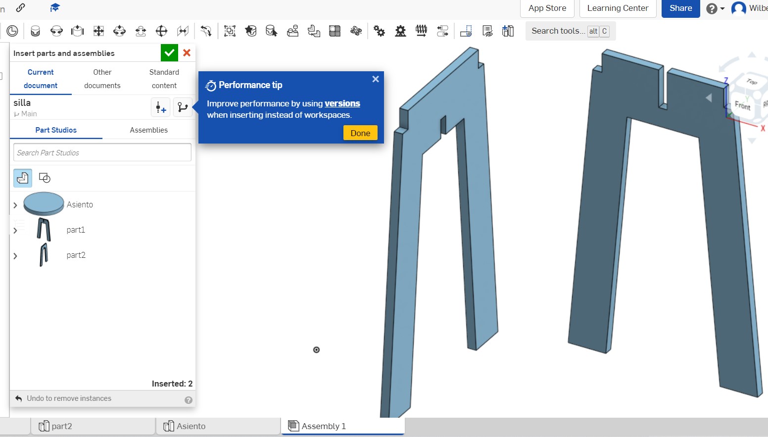
In the assembly sheet we insert the three figures to be joined.
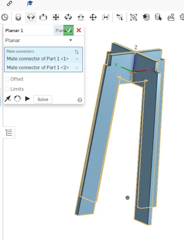
Next we join the two objects as shown.
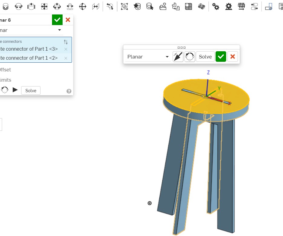
Then we assemble the third object that corresponds to the seat. In this way, the pressure assembly methodology can be simulated in the Onshape program.
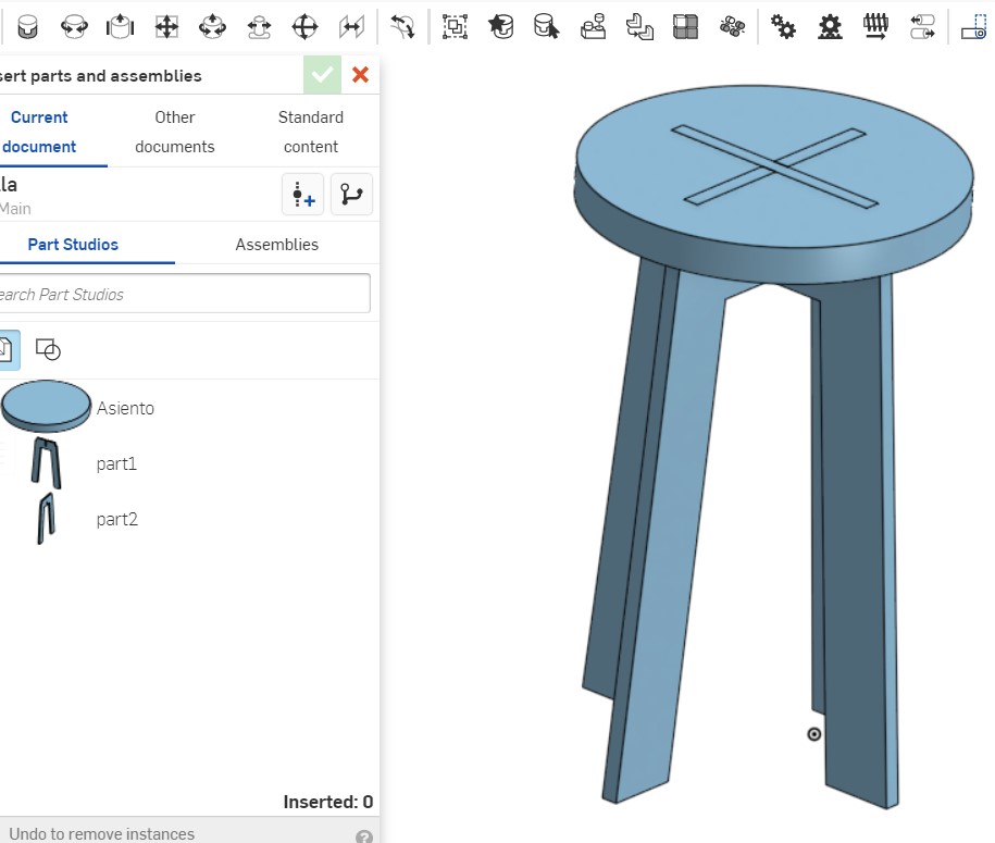
Below is a preview of how the stool looks
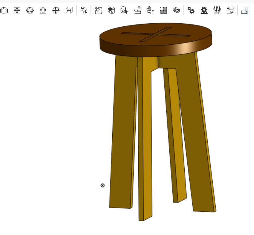
Then custom colors are assigned, so the final design remains.

Starting with the printing of the first piece
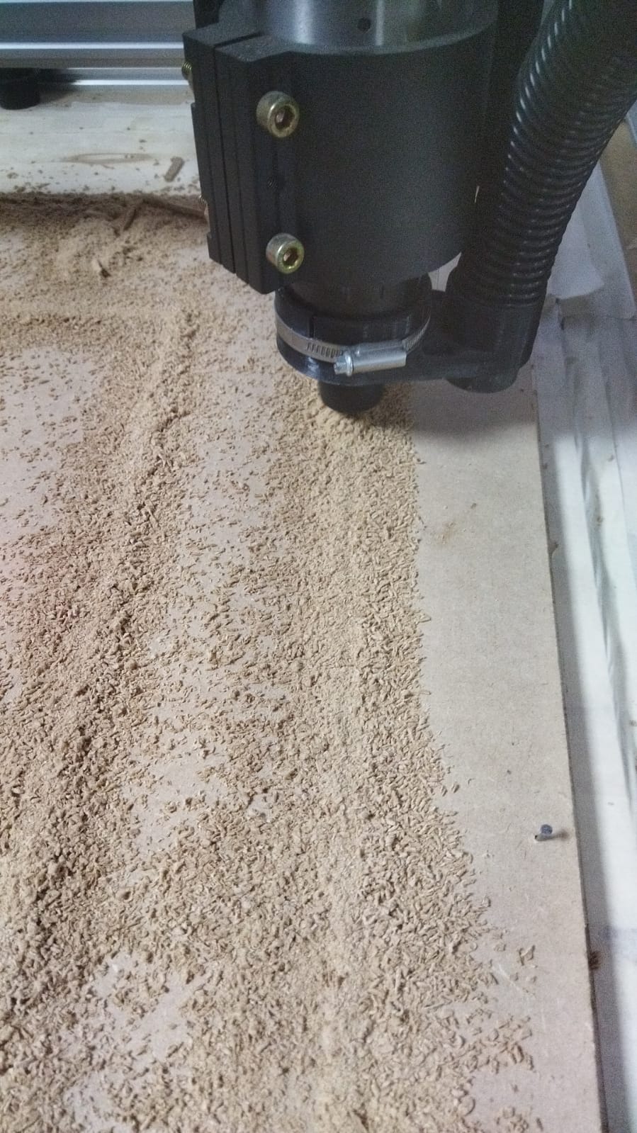
Second piece cut with a CNC machine

Supervising the work of the machine in case any problem occurs

Finished piece of stool legs
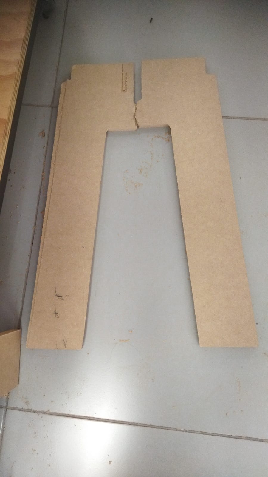
Accident on one of the legs of the stool while adjusting it and then it broke.
 After the incident of breaking the 15 millimeter thick material, the second time the supports were able to fit well, but the upper part broke at one end when it was being assembled as can be seen.
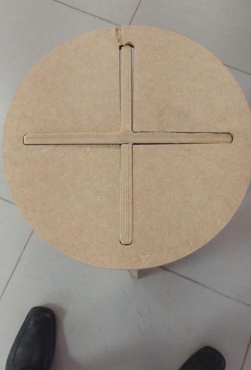
 In another view of the image you can see the second incident in the center piece.
CONCLUSIONS
The CNC wood router is an automated machine used to make cuts, engravings and complex shapes in wood with great precision and repeatability. This type of machine is controlled by software that interprets a digital design (usually in CAD format) and translates it into precise movements of the router, achieving carving or cutting the wood according to the specified design. We must first design in a program such as onshape, then configure in the CNC router machine’s own program