Computer-controlled Machining
Week 7
Group assignment:
- Do your lab's safety training
- Test runout, alignment, fixturing, speeds, feeds, materials, and toolpaths for your machine
Group 1
Group 2
Group 3
Group 1:
- Hans Moncca
- Maryori Vasquez
- Maria Angela Mejia
- Cristian Loayza
- Silvana Espinoza
- Jesus Lucero
- Jose Alberto Rodriguez


DO YOUR LAB'S SAFETY TRAINING
TRAINING
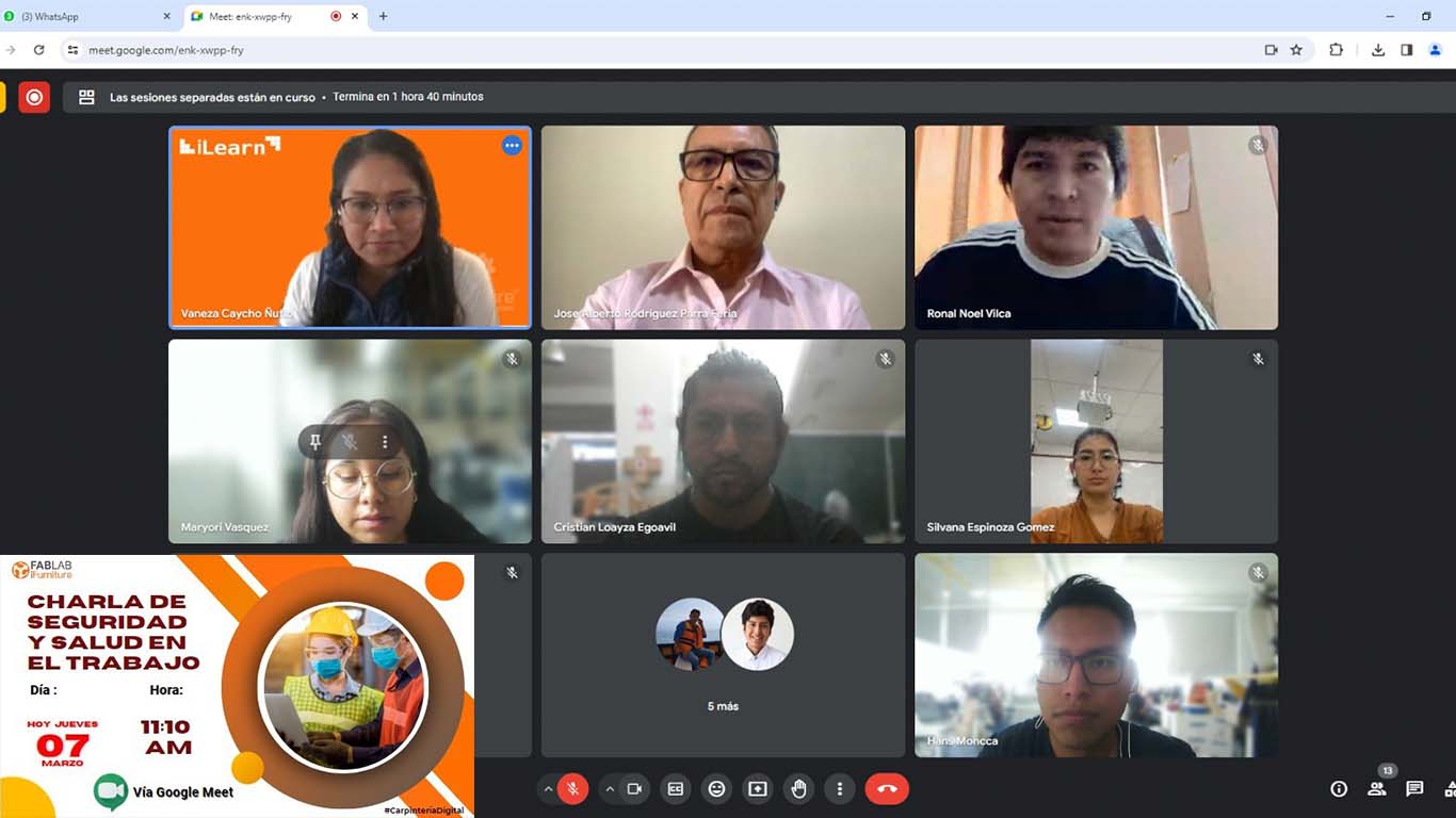
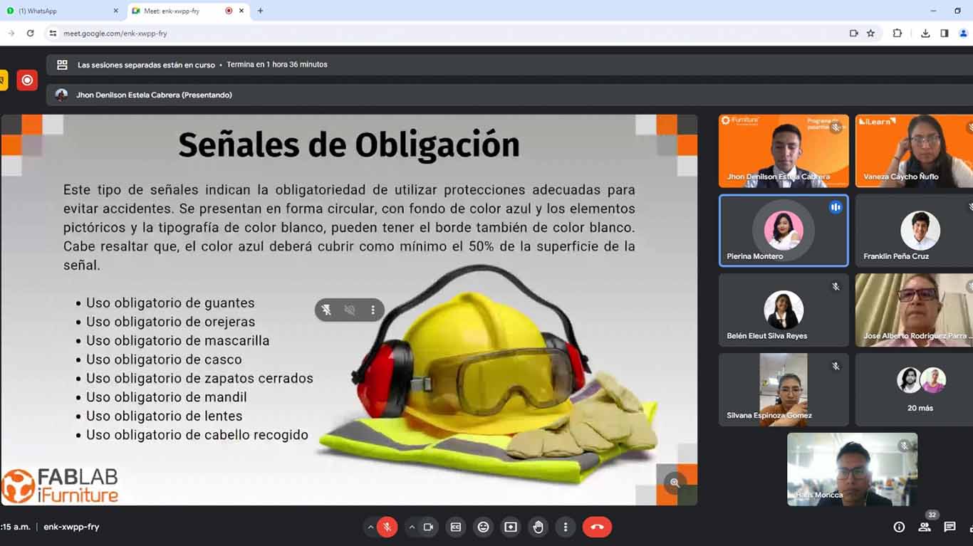
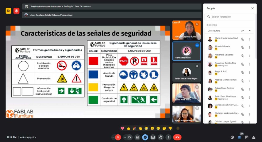
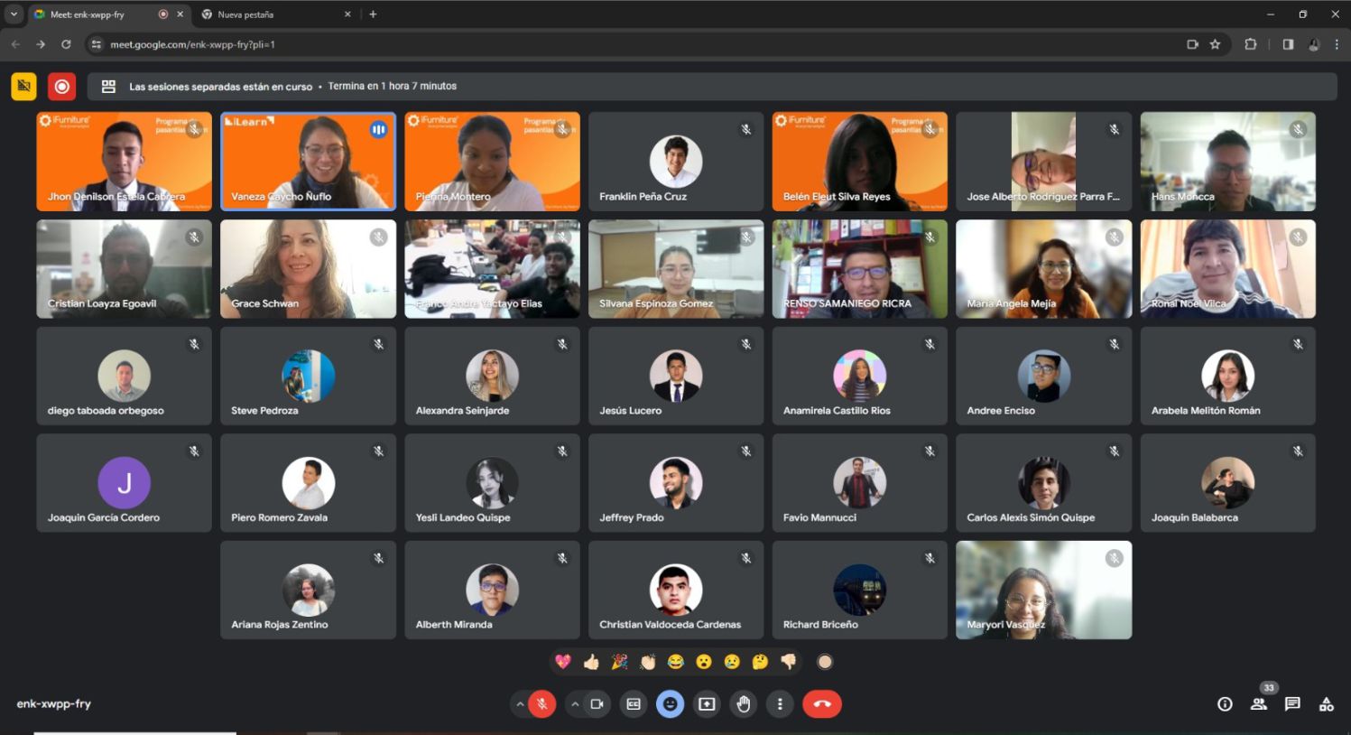
On Thursday 03/07, teacher Vaneza organized a virtual training for us from engineers to explain to us about SAFETY AND HEALTH AT WORK , especially dedicated to FAB LABS. Here we were able to receive a prior talk to learn about all the characteristics that we have to take into account to be able to work safely and avoid accidents.
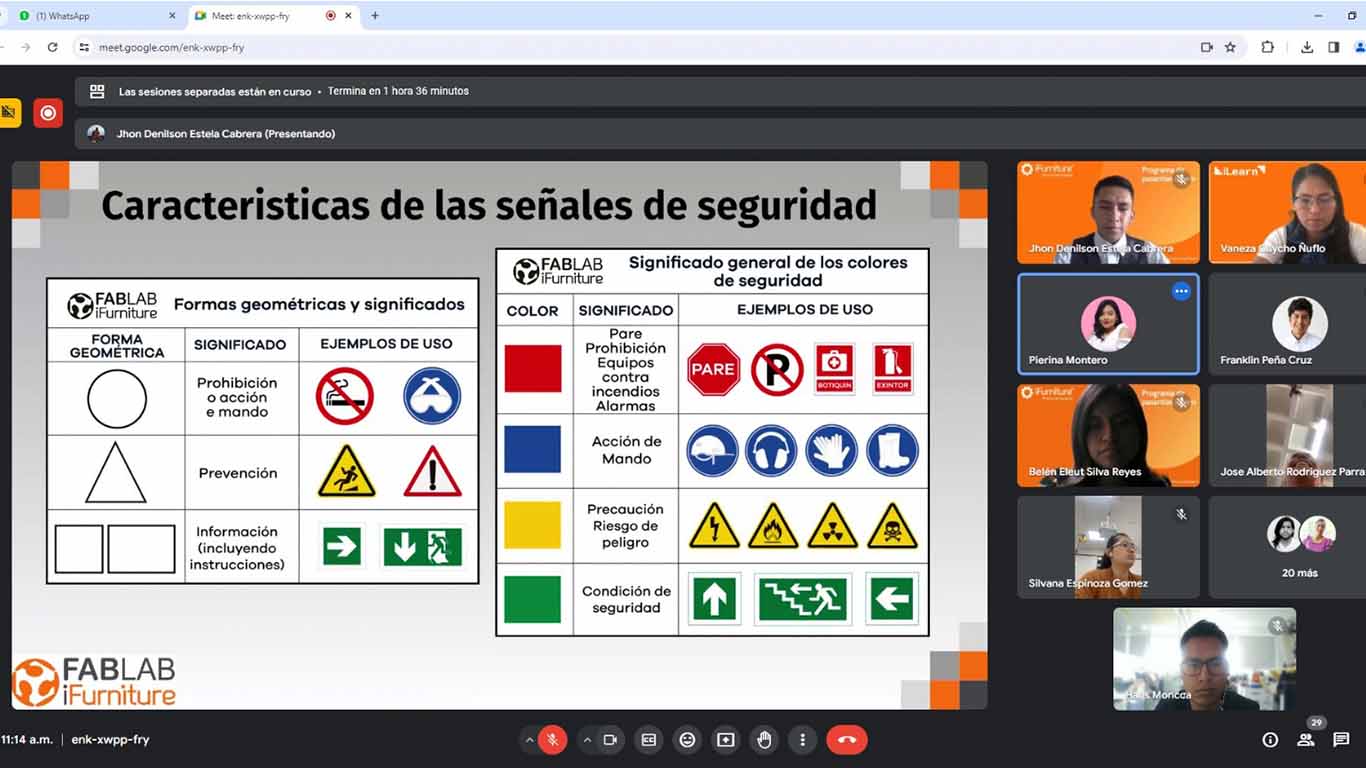
The security specialists first explained to us the signs that our laboratory must have and everything that each of them must contain. Signage in these spaces is important to avoid accidents and be safe when using machines.
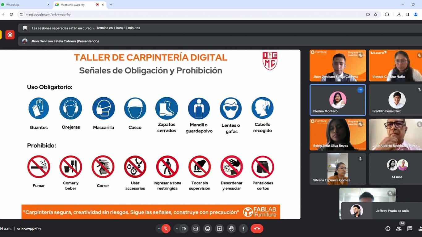
Then they explained to us about the use of "EPP" safety equipment, where we must comply with 8 important aspects to be able to work in the laboratory. Let us remember that each of them is very important for our safety and health.
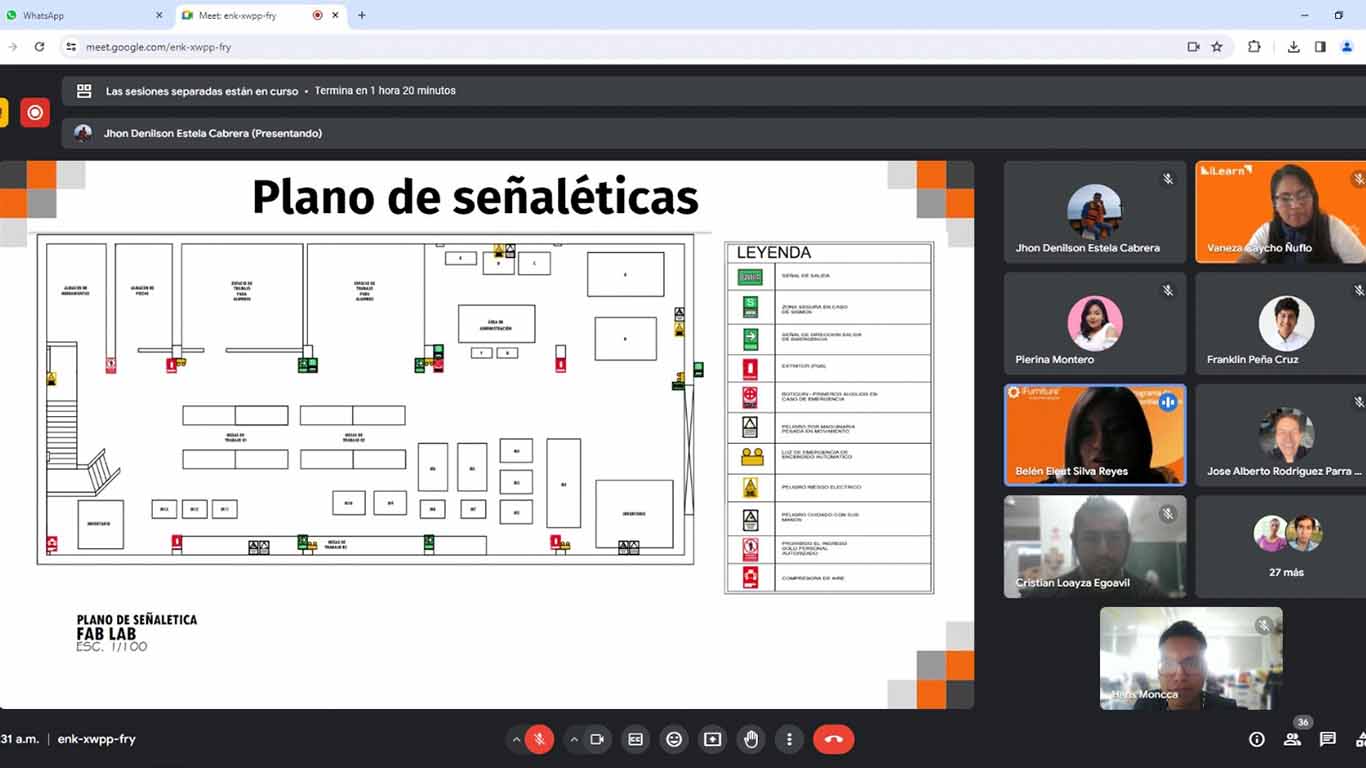
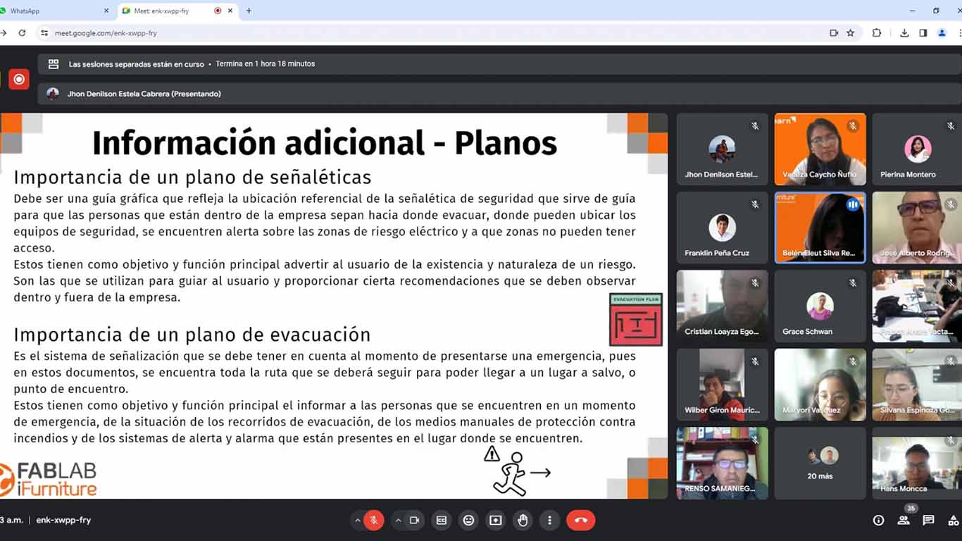
Finally, it is also important to know the laboratory, which is why they explained to us that we must have our map to know the location of each machine, safe areas and the location of fire extinguishers. The plan is fundamental for our safety and must comply with aspects that must be taken into account in our laboratories.
Here I show a screenshot at the end of the talk that was very interesting and that also made me reflect on some things that were not being taken into account in the laboratory of the Scientific University of the South.

DOING MY LAB SAFETY
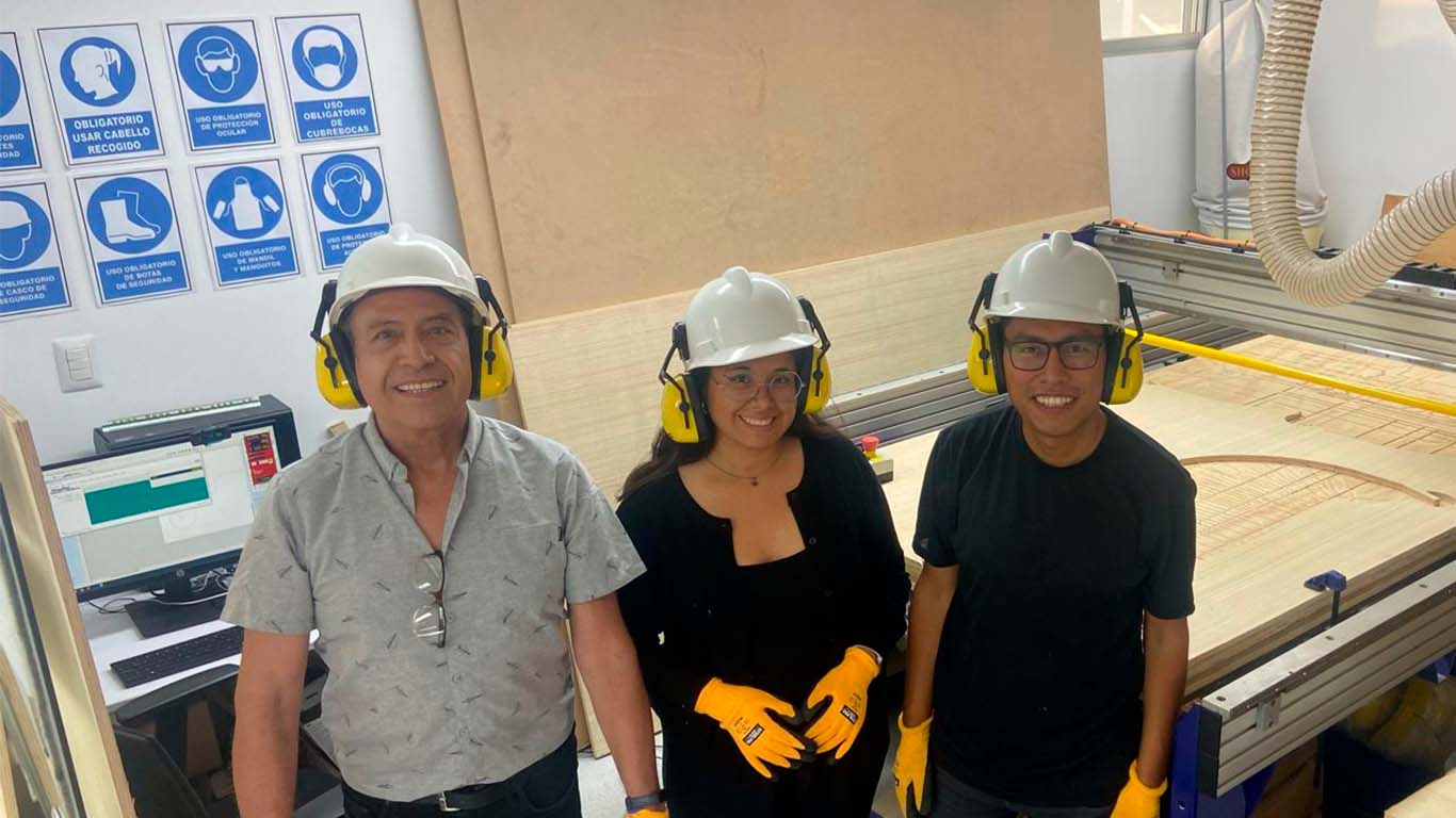
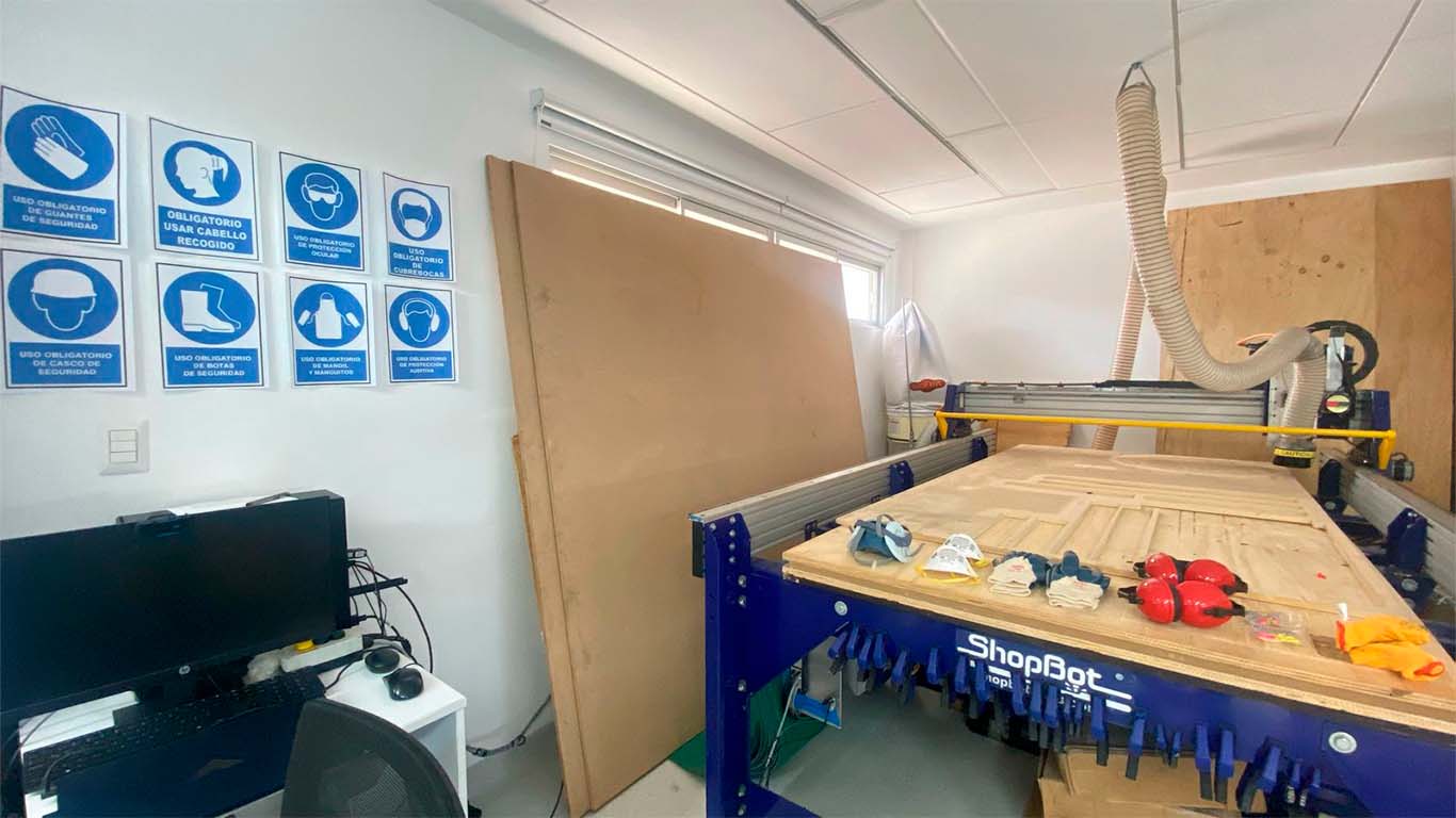
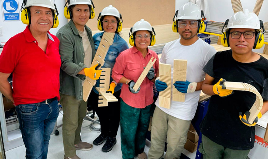
After the safety talk, my friend Maryori and I began to supervise all the aspects that we must consider in the FAB LAB. So we got our safety equipment ready and we also checked if we had all the signs, but to do it and be able to comply with the safety aspects and be able to start working.

FEATURES, CONFIGURATION AND IMPLEMENTS OF THE CNC MILLING MACHINE
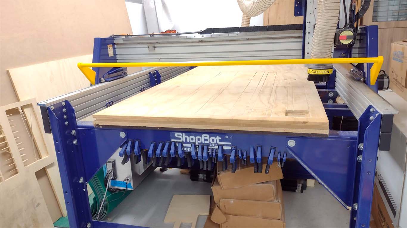
SHOPBOT PR-ALPHA
The CNC router machine that we have at the Universidad Cientifica del Sur is the SHOPBOT PR ALPHA MODEL 96 - 48 , which has the following technical specifications:
| CUT / MOVEMENT AREA | 105” x 61” x 8” |
|---|---|
| XY POSITIONING SPEED: | Variable, max. 1800”/min. |
| Z POSITIONING SPEED: | Variable, max. 900”/min. |
| LINEAR CUTTING FORCE: | Approximately 150 lbs. |
| INPUT VOLTAGE: | 220v single-phase, 230v 3-phase and 380/460V 3-phase power options are available, depending on tool and configuration. |
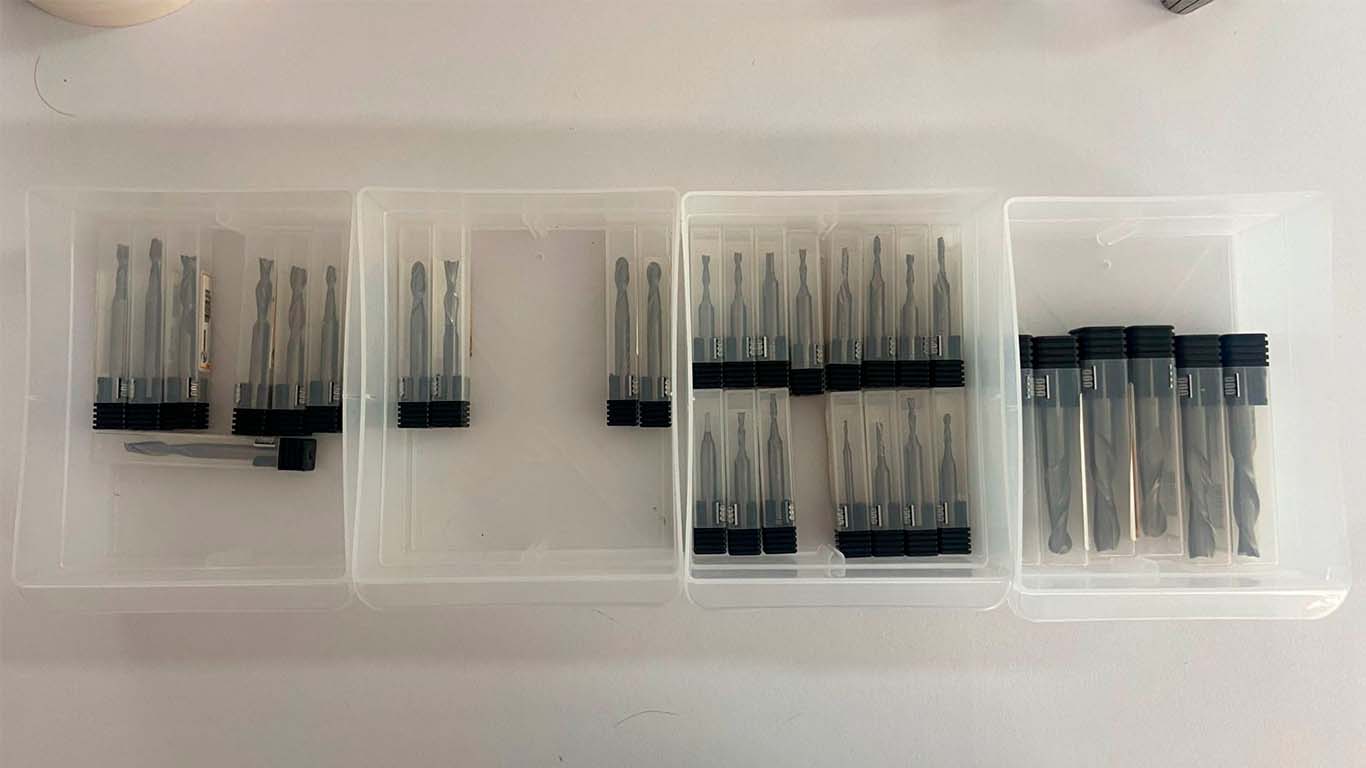
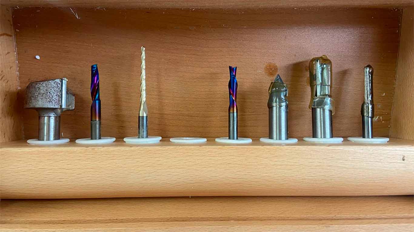
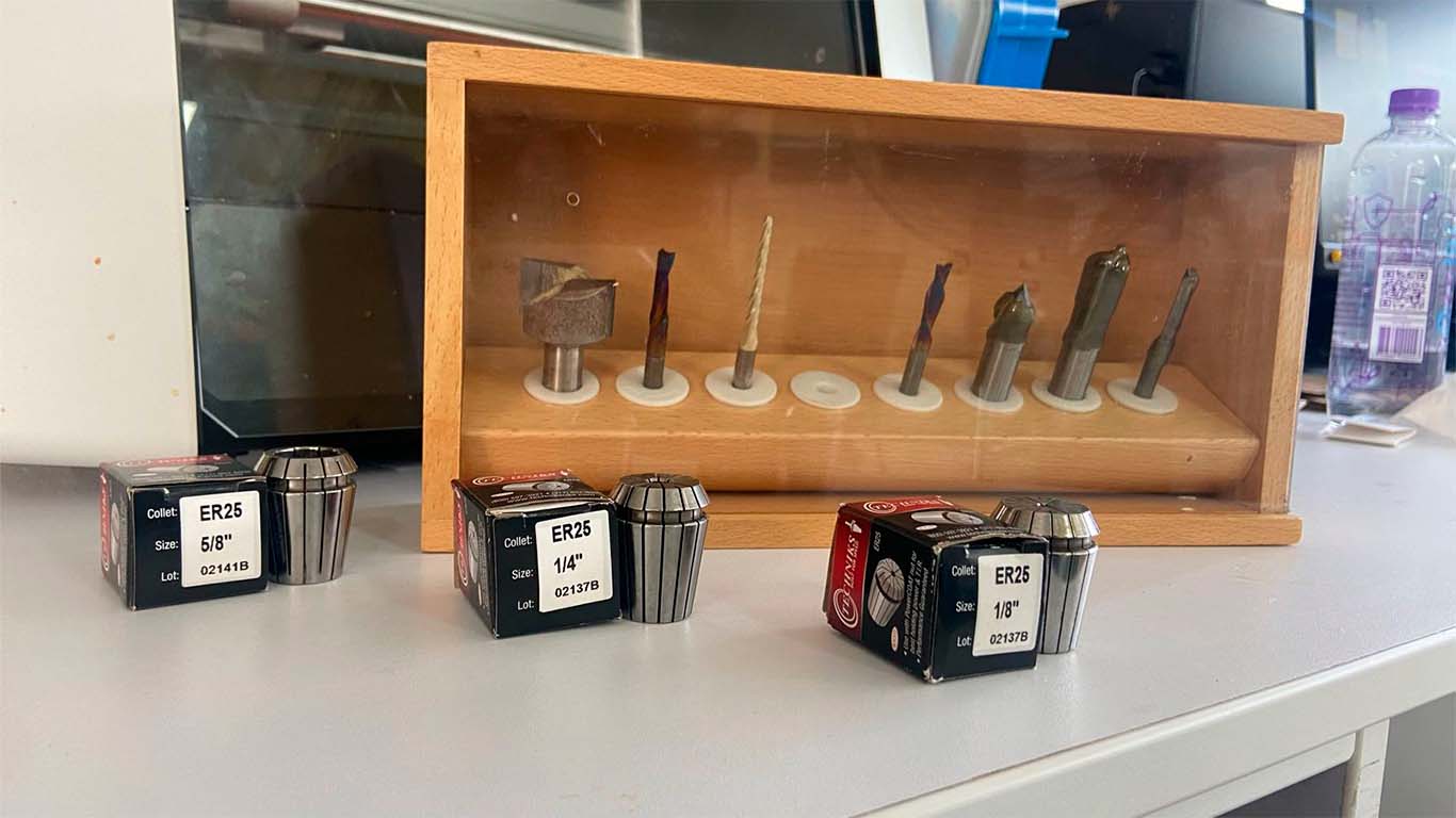
FAB LAB UCSUR IMPLEMENTS
At the FAB LAB UCSUR we have the following implements for the CNC router machine. 1/4", 1/8" and 5/8" cutters together with their ER25 collets and a cutter that comes with the SHOPBOT. For our group and individual work we will use the 1/4" cutters, together with their appropriate collet since we have many more spare parts in case we have some problems and we can do the work.
VCARVE PRO - CAM
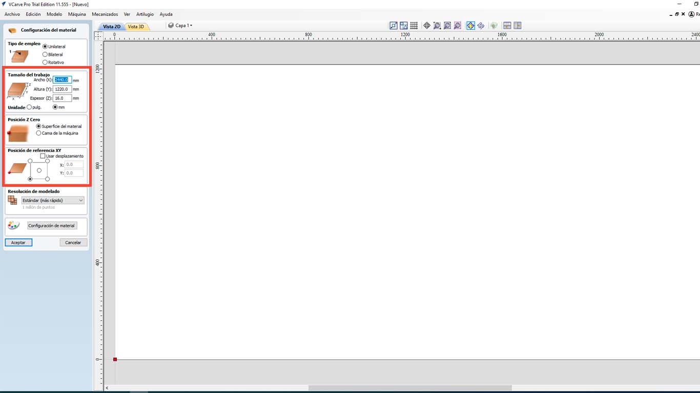
At the FAB LAB UCSUR we have the VCARVE PRO program that we use to use the CNC router and the following steps will be carried out with all the tests and with any document that we want to send to be cut. First we open VCARVE PRO and configure our material. In this case we have a 2440 x 1220 mm x 15 mm plywood . But to achieve a better cut of the pieces, we will increase + 1 mm, that is, 16 mm and be able to achieve the exact piece.
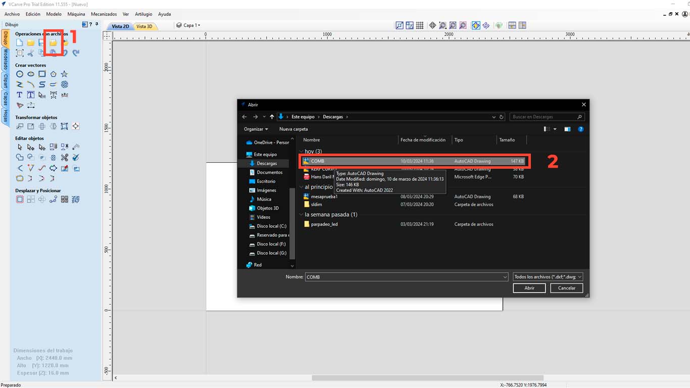
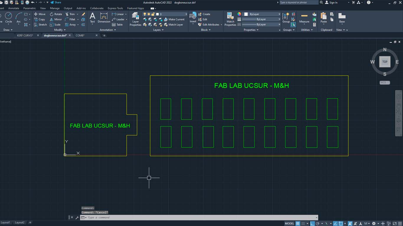
Then we import the file we want to cut, in this case I will do it with a DWG file and we select the file we are going to cut.
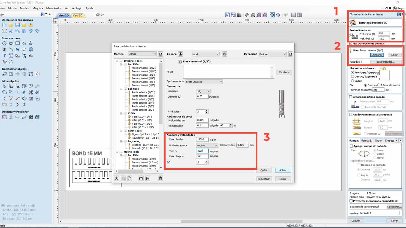
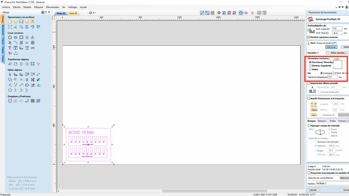
After that, we go to the upper right part of the program and we will find the "TOOL PATHS" button and look for the "PROFILE PATH" option, which is what we will use to cut the material. We have many options to do and that you can explore.

Then, in the 1st red rectangle, we check if the depth meets the entire thickness of the material. Then we check what type of cutter we are going to use and click "SELECT" to access the tool database, where we can change the size and type of cutter. Additionally, this is where we have to give the speed that the SPLINDER will have and the cutting speed. We have to be careful with it, in this case we will leave it as default.
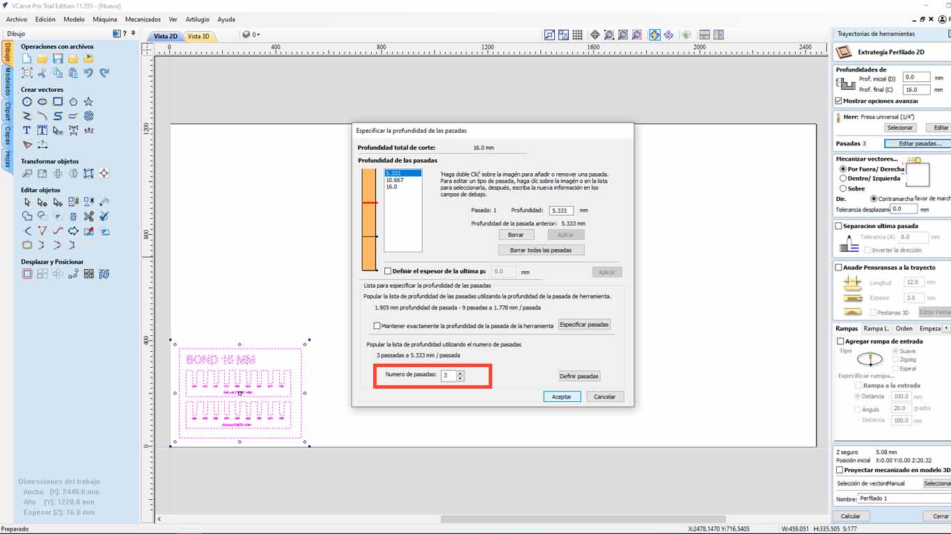
On the other hand, we also have to configure the number of passes that our milling cutter will have on the material. We have to be careful with this and in my case, I will make 3 passes to be able to cut the material.
Finally, we have to analyze if we want our cut "OUTSIDE", "INSIDE" or "IN LINE" , this to know what we want. What I discovered is that on the outside it is when it is cutting pieces, on the inside it is used in holes or bones and in Line to make marks like what we are going to use to do the curve tests and accept.
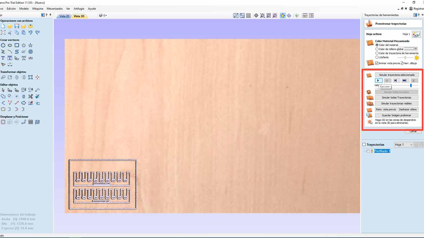
The program will send us to the 3D view, where it will show us a simulation of the cut that the machine will make. Here, we can see if there are any lines that are not being cut or there are some problems. Finally, we save the trajectory and we will go to the machine.


CONFIGURATION THE SHOPBOT PROGRAM
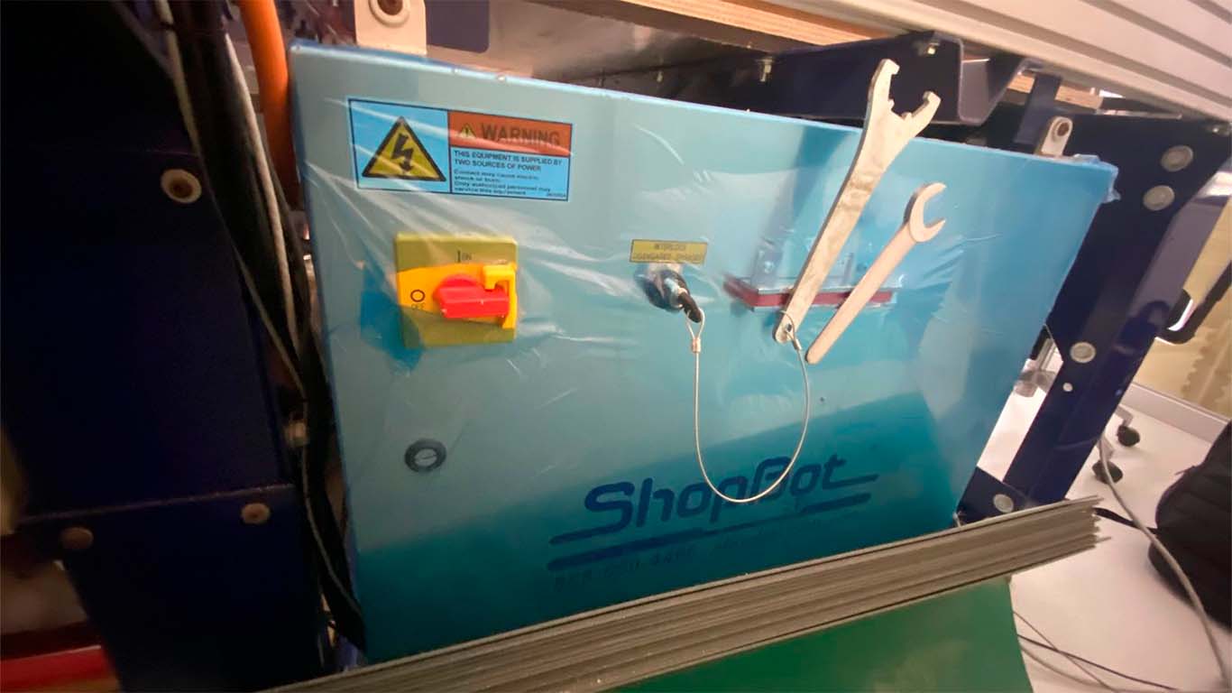
It is important to locate the safety and power box of the SHOPBOT since this is where we will turn on the machine and also activate the SPLINE. Remember to turn it off when changing the mill cutter or spring collet.
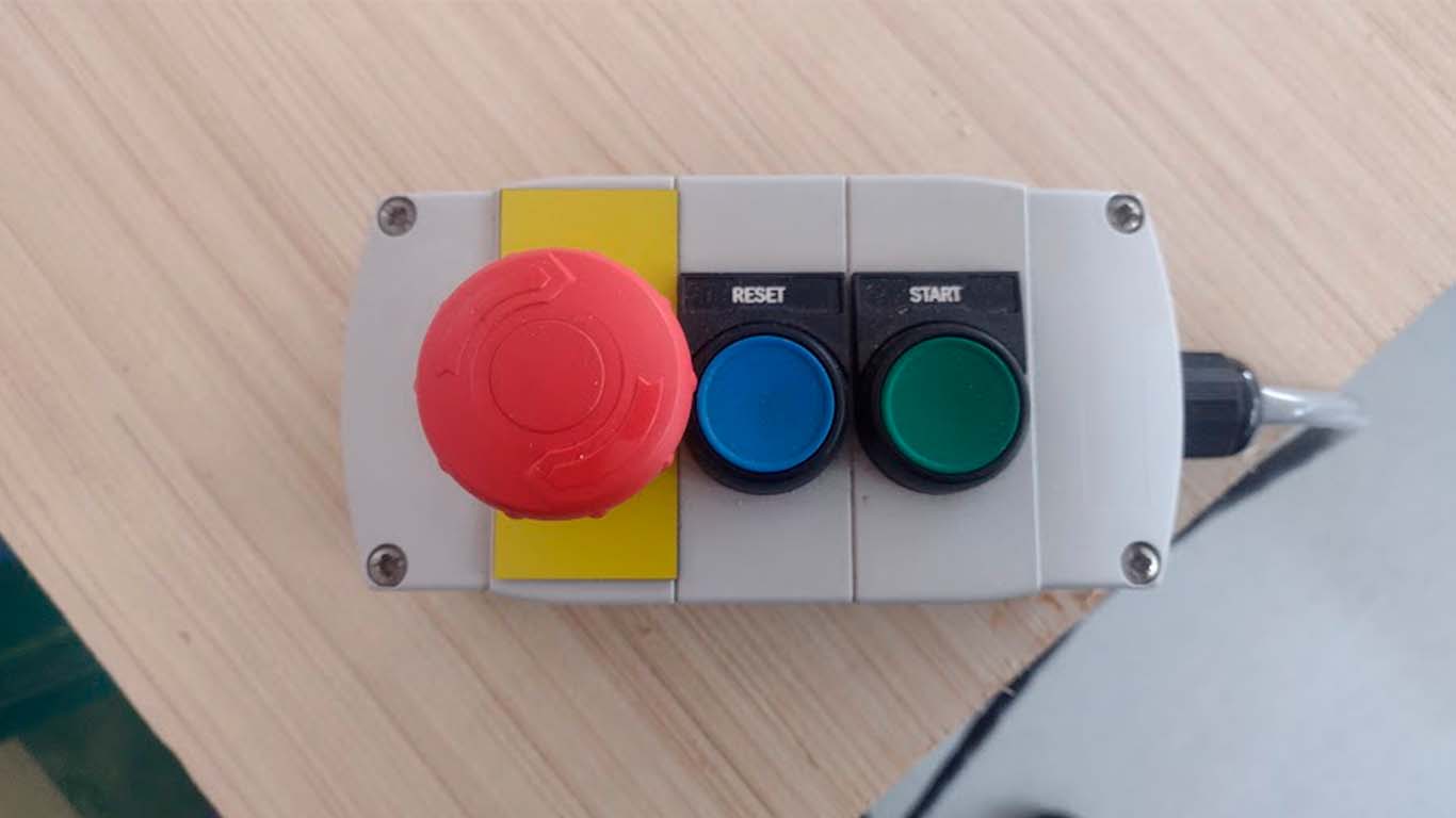
We have to remember that the SHOPBOT presents this control to be able to control the SPLINE at the time we want to activate it and presents an emergency button in case of any accident that may occur. We always have to have it in hand every time we use the machine for our safety and that of our colleagues.
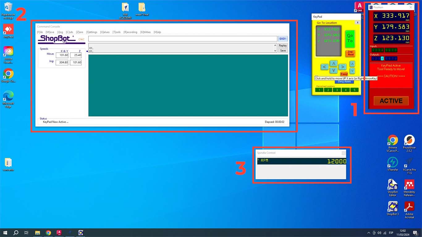
To use the SHOPBOT machine we first have to open the program, then we have to calibrate the X, Y and Z axes. In the case of our machine, we have already calibrated the I will show what the calibration of the Z axis is like. When you open the program, 3 windows will appear. The POSITION is where we perform the calibration, movement and control of starting or stopping the machine. The second window is COMMAND CONSOLE where we can open the trajectories, warm up the machine and, if it is the first time using it, its configuration. Finally, we will have the SPLINDER, which is the speed at which the machine is working and which is important when cutting.
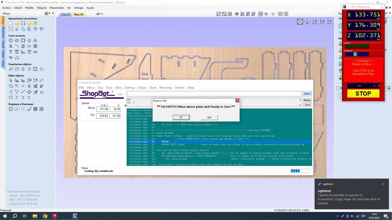
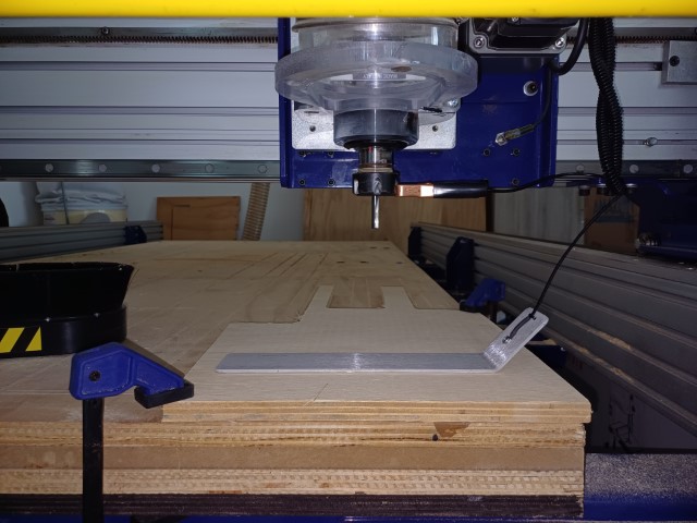
To calibrate the Z axis, we have to click the Z button in the Position window. Before calibrating, we have to place the hook on the SPLINDER and the metal plate on the material, so that the machine can be calibrated as we can see in the photograph and avoid breaking the entire splinder as it can cause this.

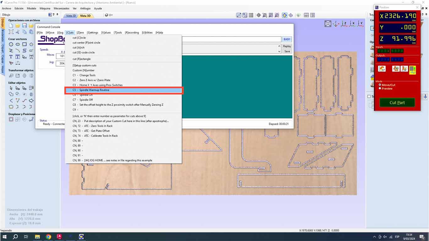
Then we will preheat the SPLINDER , this step is very important when using the machine. The trained personnel told us that it is important to carry out this step to be able to start working with the machine. The recommendation I make is that when we are going to use the machine, we have to follow the following steps and after cutting some pieces, if the machine is stopped for more than 15 minutes, the preheating has to be repeated again, this to extend the useful life of the machine. We go to the COMMAND CONSOLE window, we go to the CUTS tab and look for the SPLINDE WARMUP RUTINE button, this is to preheat the machine.
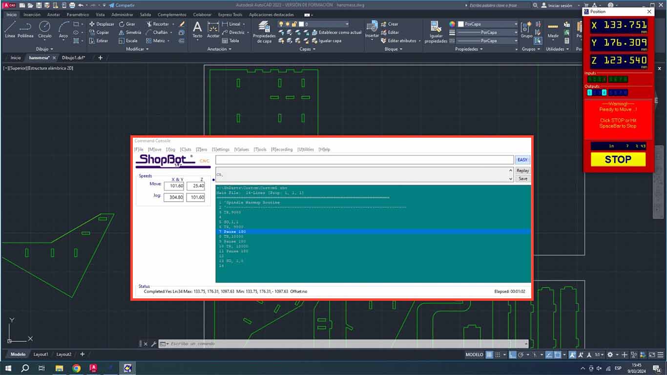
A routine window will appear for the SPLINDER that will change speed until it reaches 12,000 and this routine will warm up the splinder before starting to work. And when you press the START button on the shopbot, the SPLINE will spin until the routine is finished, which lasts approximately 10 minutes.
TEST RUNOUT, ALIGNMENT, FIXTURING, SPEEDS, FEEDS, MATERIALS AND TOOLPATHS FOR YOUR MACHINE
TEST COMB
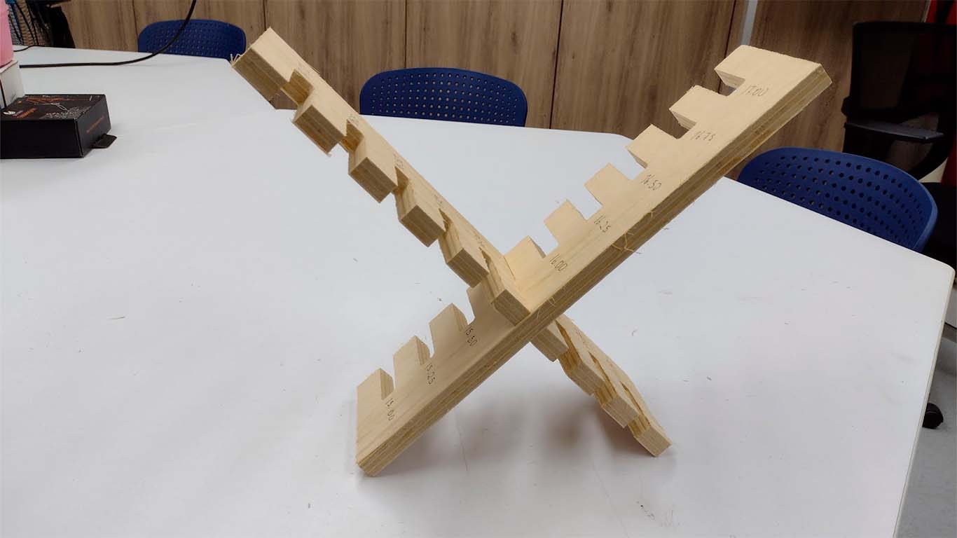
The first test we perform is the COMB, which is to find the right fit. For all tests we will use the 15 mm PLYWOOD that will be used in our individual work as well. First we thought that the comb was similar to what we did in week 2 with the laser cut and it was not like that. Well, the idea is that the 15 mm plate can fit with another similar piece and instead of enlarging it, we reduce it and it will never fit. Bad calculation, here is a photo of our first comb.
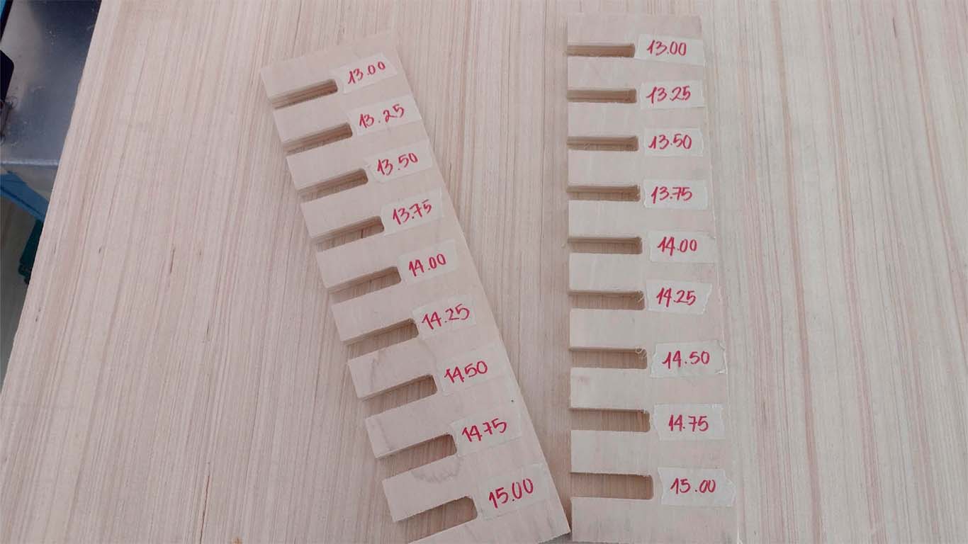
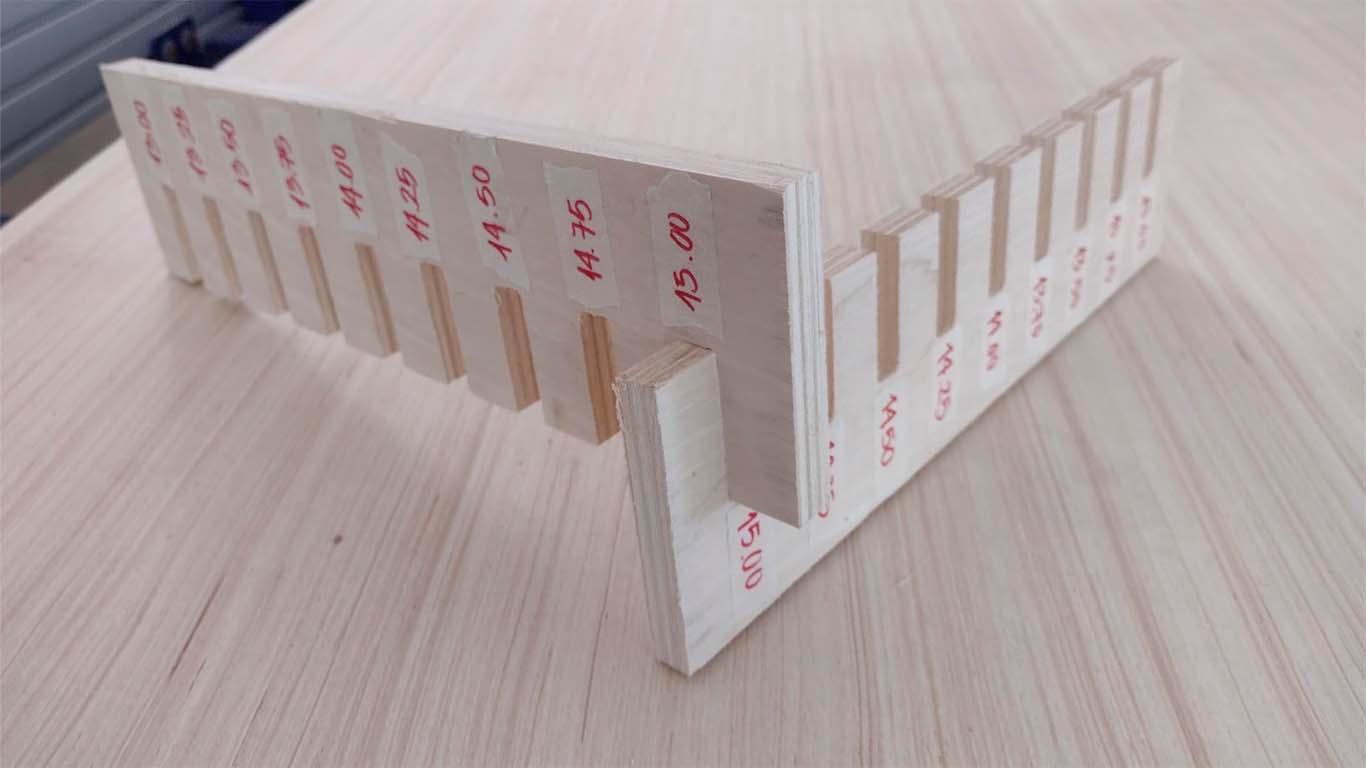
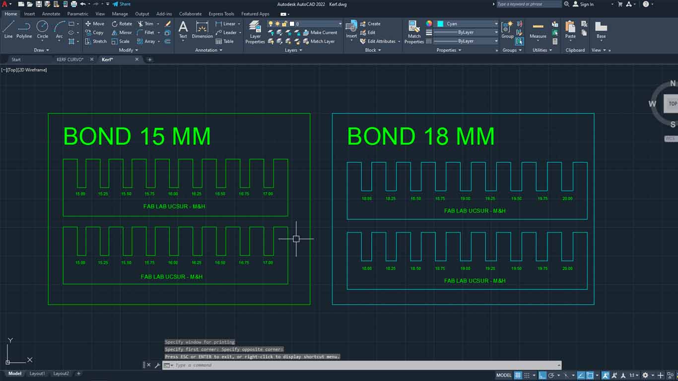
Later, we did was make the drawing in AUTOCAD where we made the bond taking into account the thickness of the material, which is 15 mm, and we gave each section a value of +0.25 mm to see what measurement was appropriate for a correct fit. . Here the process:
| NUMBER OF PASES: | 3 |
|---|---|
| SPLINDE SPEED: | 18000 RPM |
| RATE: | 5000 mm/min |
| CHIP LOAD: | 0.1389 mm |
| CUTTING AREA: | OUTSIDE |
After cutting both combs, we can analyze and verify that the best joint for joints that are like this is for the cuts to have +0.75mm of the thickness of the material. In this case, for the 15 mm material, the ideal cut would be 15.75 mm for a better fit of the pieces. One observation, we forgot to make the dog bones and the chamfer that the corners must have so that they can be joined more easily.
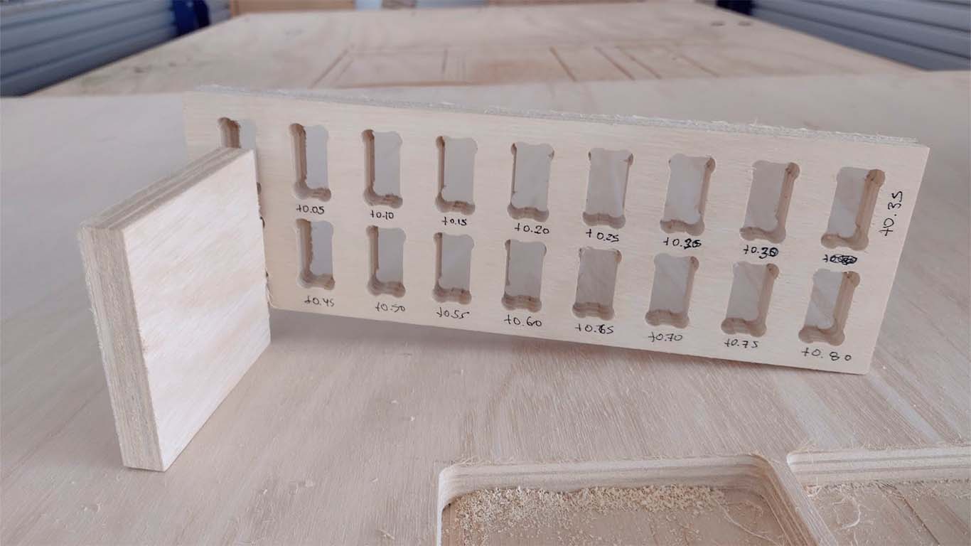
DOG BONE AND HOLE TEST
The second test is the dog bone and the hole. The idea of the test is to know what size is needed for the pieces to fit well in the holes. The DOG BONE test is to make it easier for us to insert the pieces between them and to ensure that the corners do not have problems, this mainly applies to the FEMALE pieces. On the other hand, the hole test is to know what size the female piece will be so that the MALE piece can enter without problems and without damaging the material.
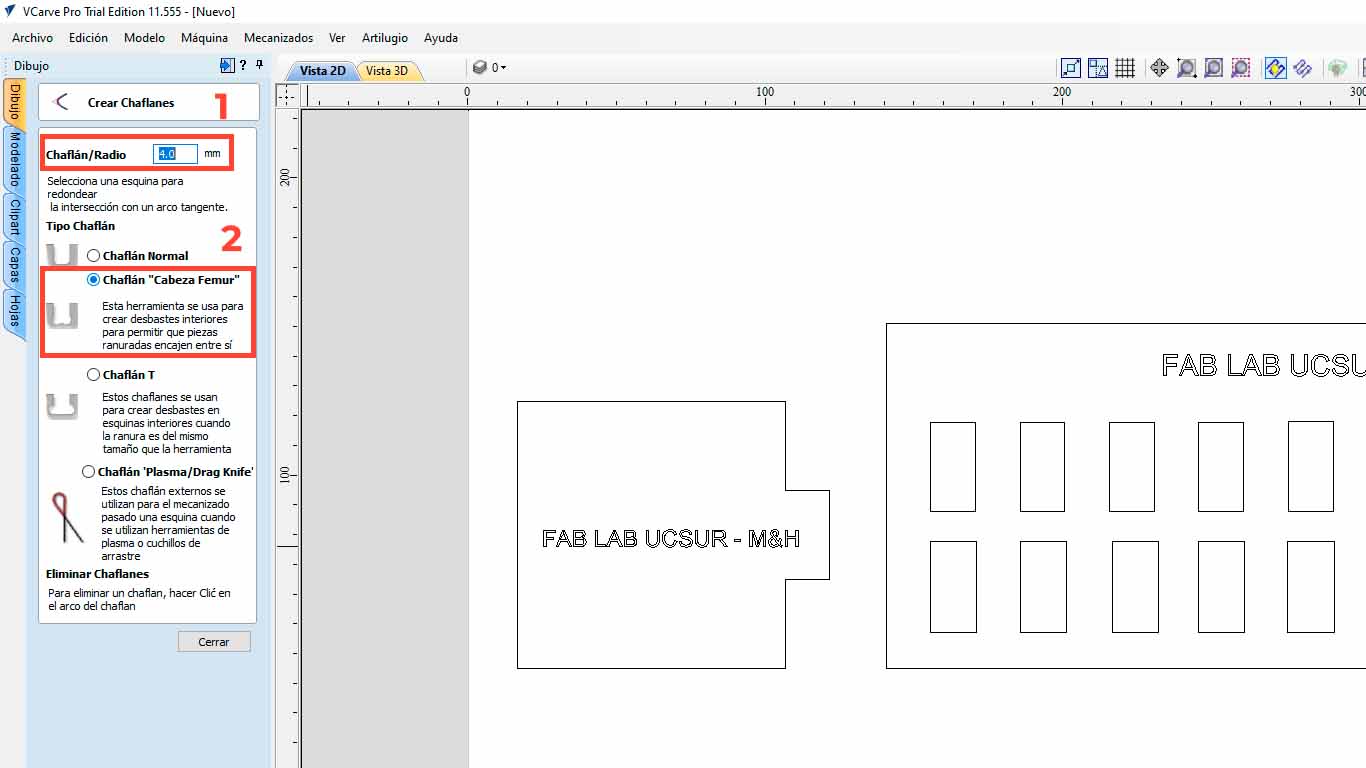
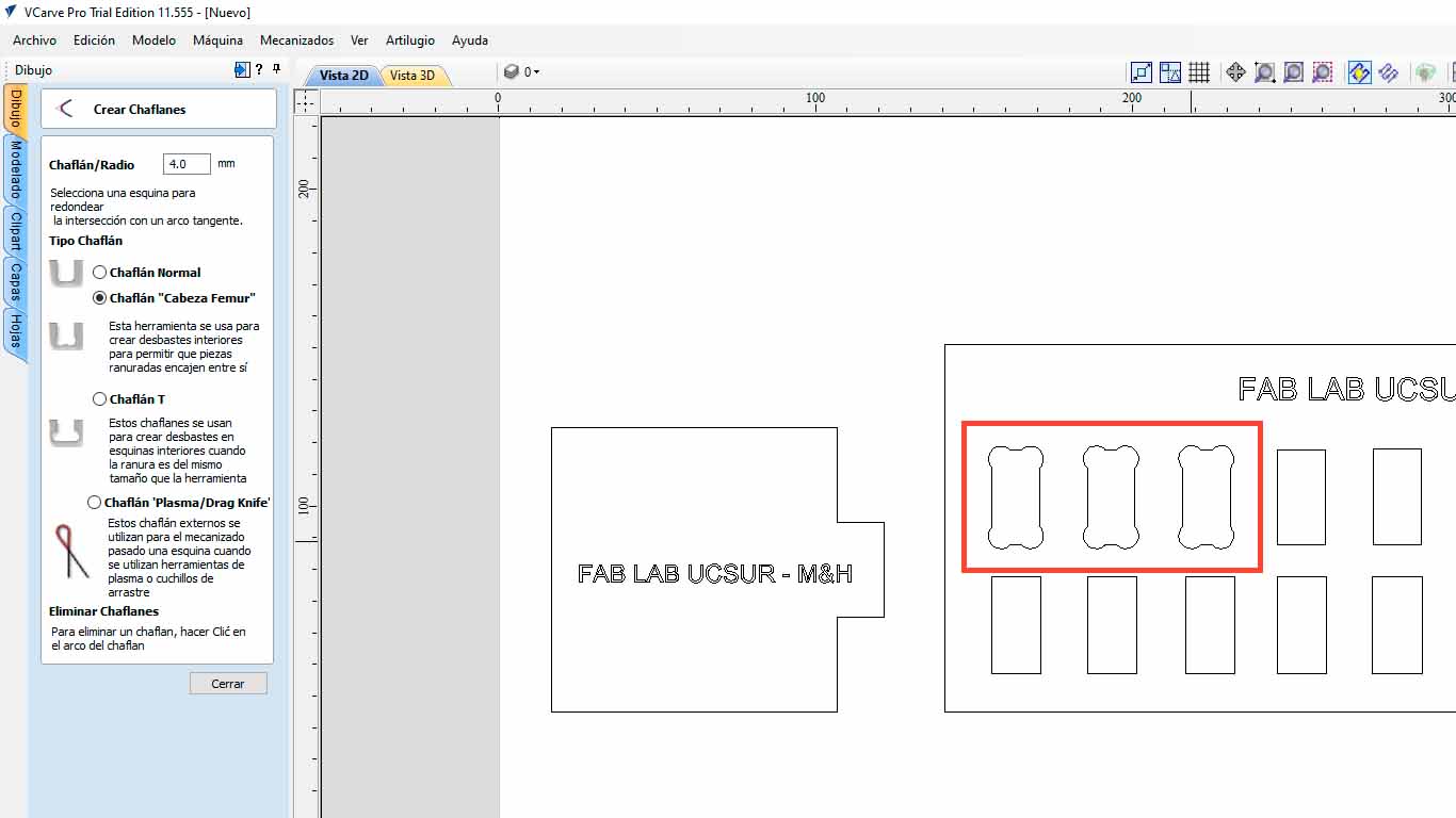
To give the DOG BONE shape, we can do this in the VCARVE PRO after having the pieces designed. When importing, we go to the CREATE CHANFLES button.
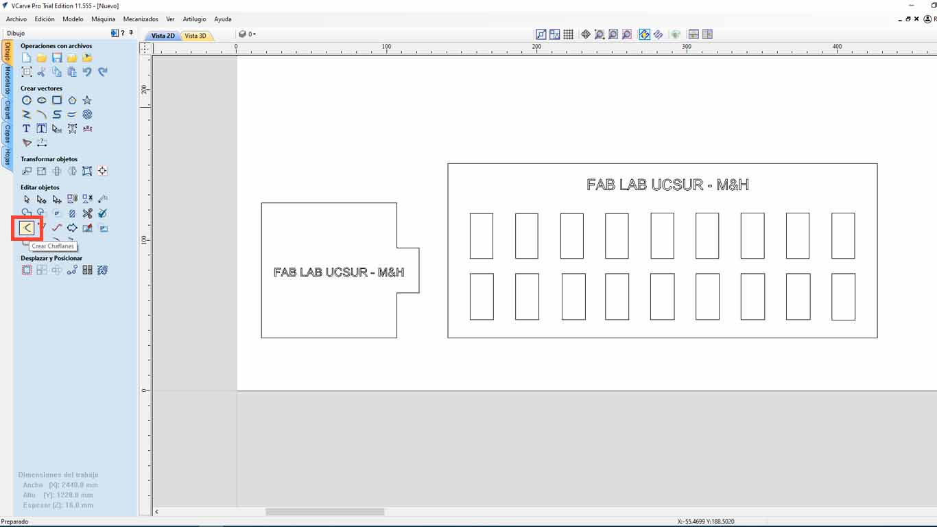
Here we configure the size of the radius that we want the corners to have, in this case we will use 4 mm and we will also choose the FEMUR HEAD , which gives it a bone shape that is better for wooden pieces. Then we click on the corners that we want to make the corner change to DOG BONE and we will have done it.
After modifying all the holes in the imported file and sending it to be cut, we can see the difference and this process is important so as not to damage the materials and the pieces fit better. Here I leave the table of the characteristics taken in the VCARVE for the cut and the cut piece.
| NUMBER OF PASES: | 3 |
|---|---|
| SPLINDE SPEED: | 18000 RPM |
| RATE: | 5000 mm/min |
| CHIP LOAD: | 0.1389 mm |
| CUTTING AREA: | OUTSIDE |
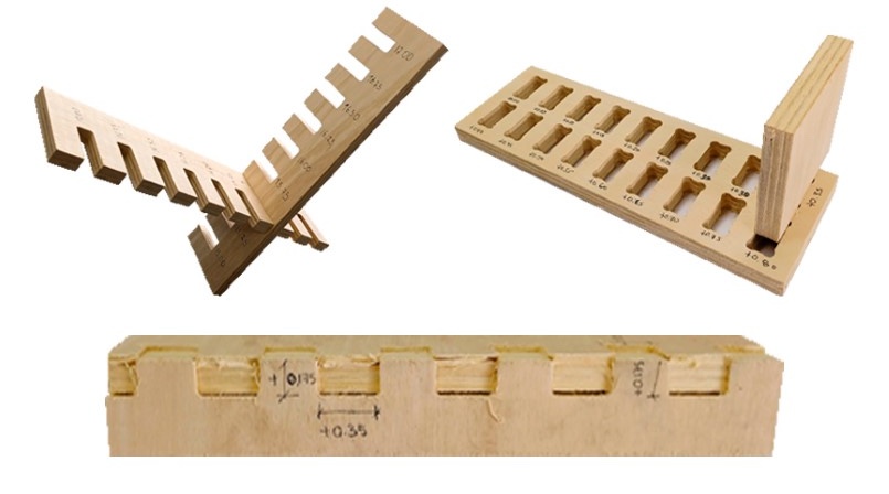
In the following image we can see that the MALE piece easily fits into the +0.40mm hole, that is, if the piece has a thickness of 15 mm, we need the female piece to have a hole of +0.40mm, in this case 15.40mm. And we add this same calculation to the height of the female piece, in order to obtain a suitable female piece and we can have a perfect fit, without the male piece entering with too much force or coming out easily. For this the test helps us a lot.
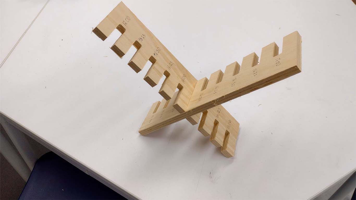
CURVATURE TEST
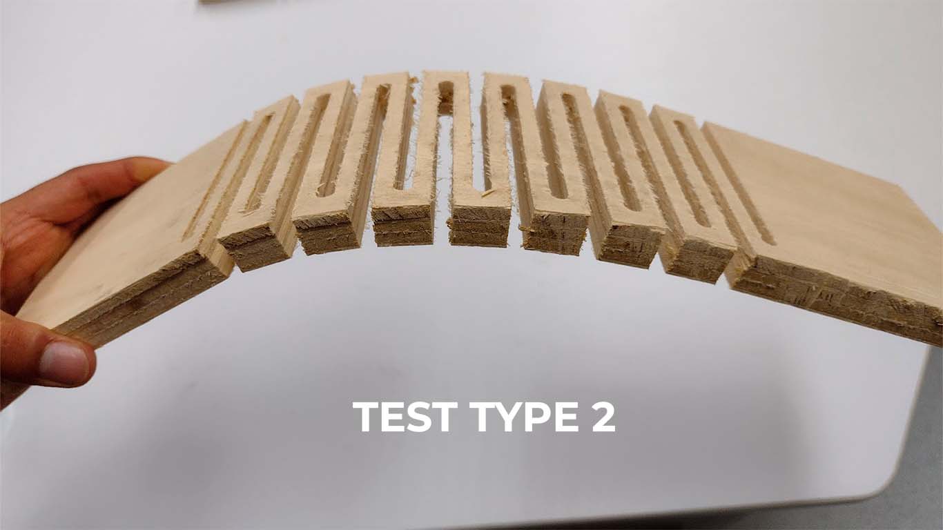
The next test is to convert a rigid element such as plywood into curved elements using patterns that are cut into them and we can achieve different curvatures. For the next test we perform 3 patterns and be able to see the difference between them regarding curvature, flexibility and rigidity. Here I will show the characteristics that each of them have and what the advantages are to be able to achieve any curved object in wood.
| NUMBER OF PASES: | 3 |
|---|---|
| SPLINDE SPEED: | 18000 RPM |
| RATE: | 5000 mm/min |
| CHIP LOAD: | 0.1389 mm |
| CUTTING AREA: | OUTSIDE |
| DEPTH: | 16 mm |
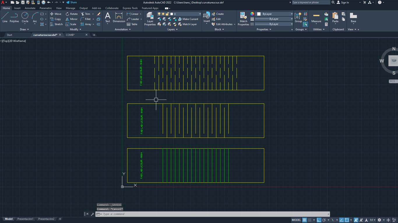
First, we import the curvature model into VCARVE PRO, then we carry out the steps mentioned above and when configuring the cut, we have to differentiate the types of cut, depth and side. For the perimeter of the tests, we will use the depth of 16mm, and the cut on the OUTSIDE.
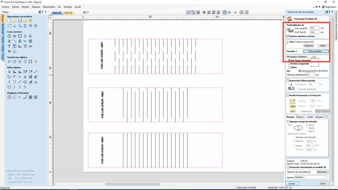
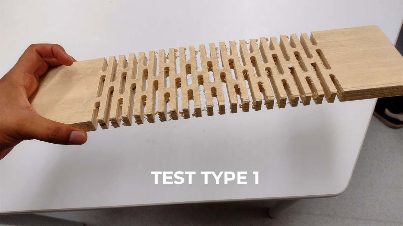
For tests type 1 and 2, we have to make the drill cut above the line, so we will choose OVER THE LINE, where the drill will pass through the designed lines that have a separation of 12 mm.
| NUMBER OF PASES: | 3 |
|---|---|
| SPLINDE SPEED: | 18000 RPM |
| RATE: | 5000 mm/min |
| CHIP LOAD: | 0.1389 mm |
| CUTTING AREA: | OVER THE LINE |
| DEPTH: | 16 mm |
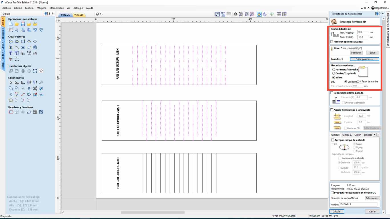
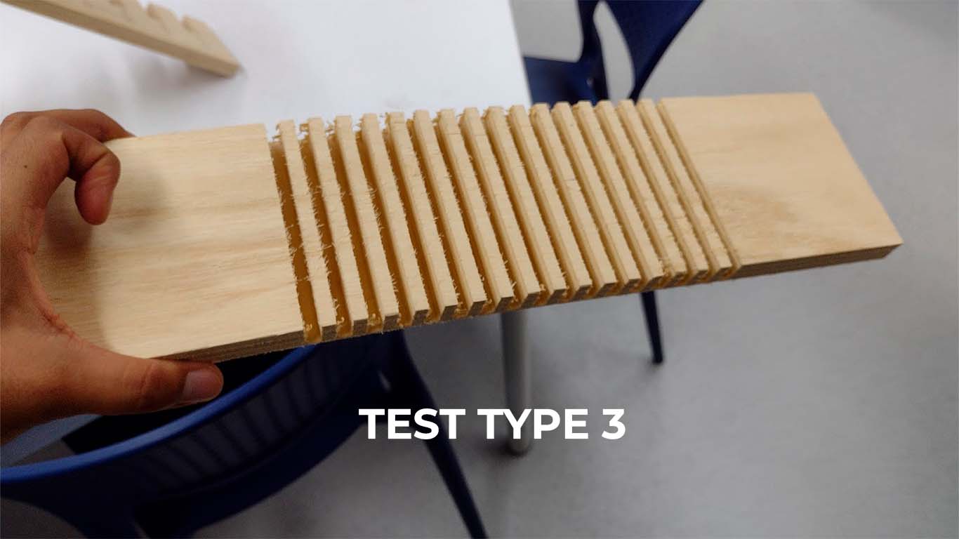
For test type 3, we only have to cut 14 mm deep since we do not want it to cut the entire thickness of the material, but we only want it to leave a little material so that it can be folded. On the other hand, the cut will also be on the designed line and 12 mm apart.
| NUMBER OF PASES: | 3 |
|---|---|
| SPLINDE SPEED: | 18000 RPM |
| RATE: | 5000 mm/min |
| CHIP LOAD: | 0.1389 mm |
| CUTTING AREA: | OVER THE LINE |
| DEPTH: | 14 mm |
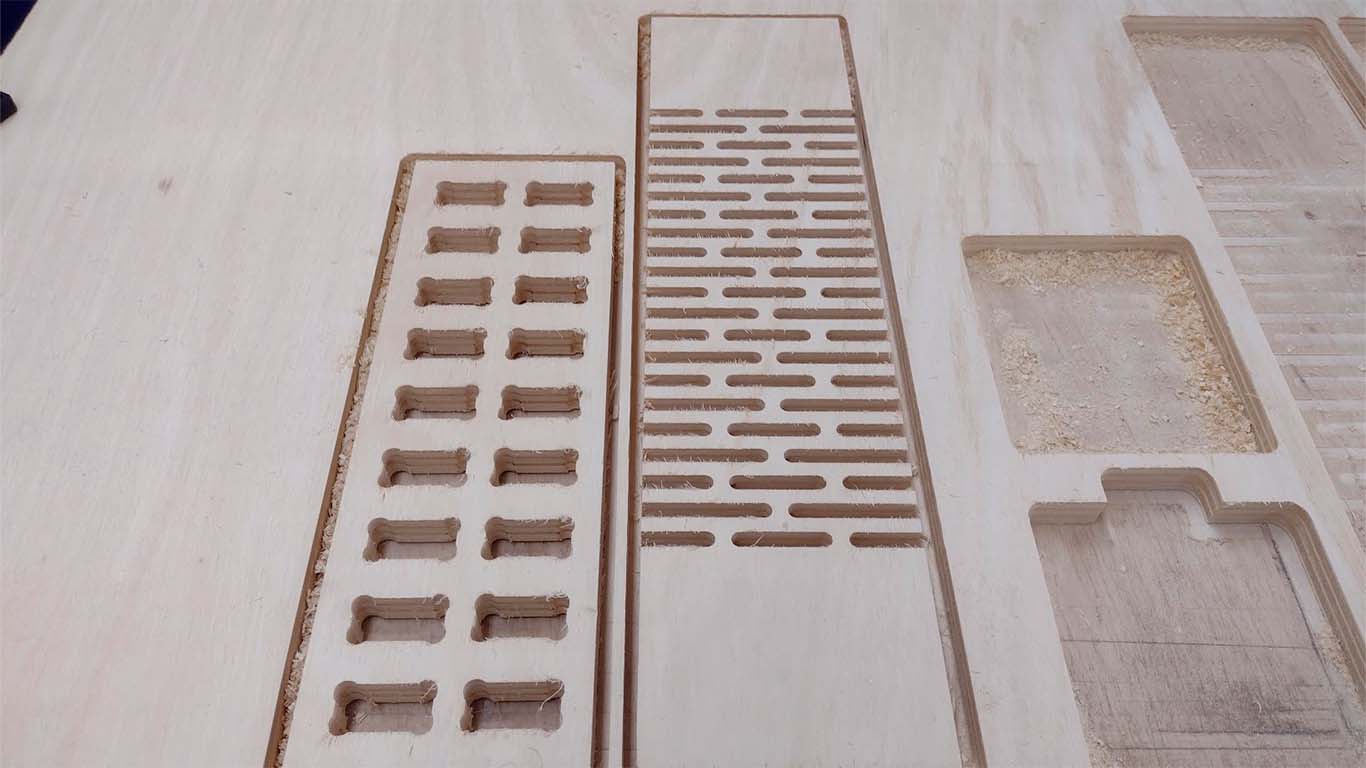
Here we have a screenshot of the cut achieved by the CNC machine from the curvature tests that we will now apply and see the flexibility that we can find in each type.
Safety Training
On Thursday, March 7 the iFurniture team gave a talk on occupational health and safety for a digital manufacturing laboratory.

Conclusions
- Follow the directions and signage in the environment: There are various signs on the floor and walls that you must pay attention to and obey
- Use appropriate safety equipment: Wear glasses, gloves, hearing protection and clothing that covers the entire body when using the machines in the Fab Lab
- Effective communication: Inform what work you will do in the Fab Lab, coordinate these activities and follow the instructions of the team in charge
Router tests
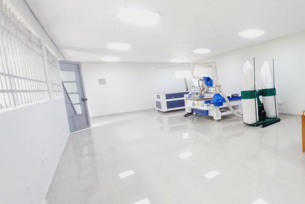
To test the parameters to use for cutting the furniture pieces, we worked as a team and went to the Universidad Cientifica del Sur (UCSUR) Fab Lab which is located in the Architecture Faculty of the university, in Chorrillos district, in the city of Lima, Peru.
Router Machine
The machine used was the ShopBot PRSalpha. It delivers rapid transit speeds of 1800 inches per minute and cutting speeds of up to 720 inches per minute. The cut/movement area is 105” x 61” x 8” (2.67m x 1.55m x 0.2m).
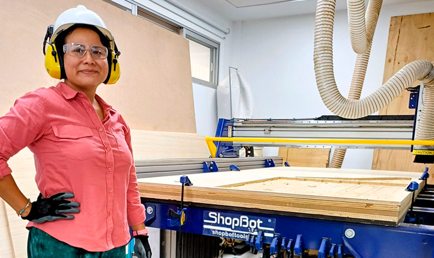
At the UCSUR Fab Lab, the protocol for using the ShopBot PRSalpha is to wear glasses, gloves, hearing protection and clothing that covers the entire body.
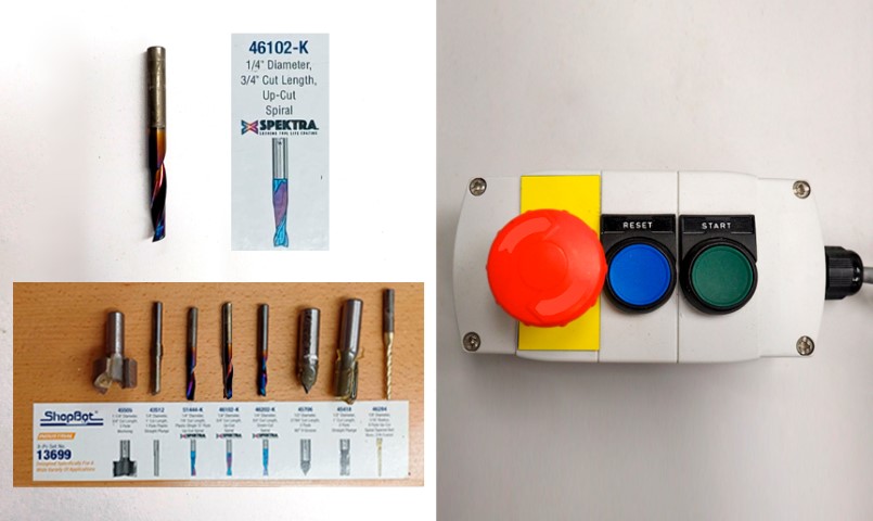
The 46102-K 1/4" diameter, 3/4" cut length, up-cut spiral mill is a versatile and efficient tool for the ShopBot PRSalpha CNC router. Its spiral design ensures cleaner cuts and smoother surface finishes by evacuating chips effectively, while also extending tool life due to reduced wear. This tool is suitable for a wide range of materials and applications, offering increased cutting speeds and minimized heat buildup for enhanced performance and precision in CNC machining operations.
Before starting any work on the CNC router, it must be calibrated following this steps:
- Preparation: Ensure safety measures are in place and power on the CNC router
- Zero Reference Point: Set the home position for the router
- Tool Calibration: Install and securely tighten the cutting tool
- Workpiece Setup: Securely fasten the workpiece to the router bed
- Axis Calibration: Calibrate X, Y, and Z axes for accuracy
- Tool Height Calibration: Set the tool height above the workpiece surface
- Speed and Feed Settings: Configure settings based on material and tool type
- Test Run: Run a test program to verify calibration accuracy
- Fine-Tuning: Make adjustments based on test results
- Documentation: Document settings for future reference
- Final Checks: Double-check all settings before production runs
Tests
To study the joints in 15mm plywood, we perform the comb test, dog bone test and the finger joint test. For the 15mm plywood in the comb test, the parameter I chose was 15.50mm. In the dog bone test I chose 15.35mm. Finally, in the finger joint test, I chose a width of 15.35mm and a height of 15.175mm.
Group 2:
- Renson Samaniego
- Wilber Giron
- Ronal Vilca Apolin
Ronal Vilca Apolin
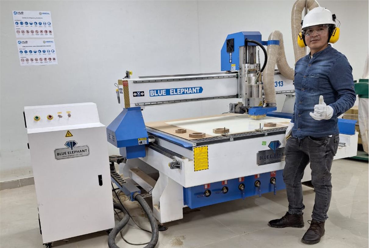
For this week's group task, the first thing we did with the Fablab Peru team was receive security training. This was necessary since we were going to put into operation a CNC Router machine, which requires expert handling and priority safety training.
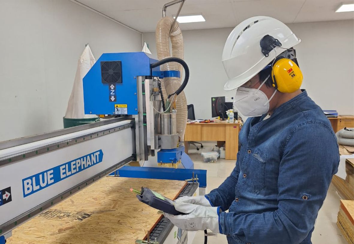
We are equipped with everything necessary to operate the machine safely. We have the essential protective equipment, such as gloves, helmet, glasses, mask, helmet earmuffs and appropriate clothing.
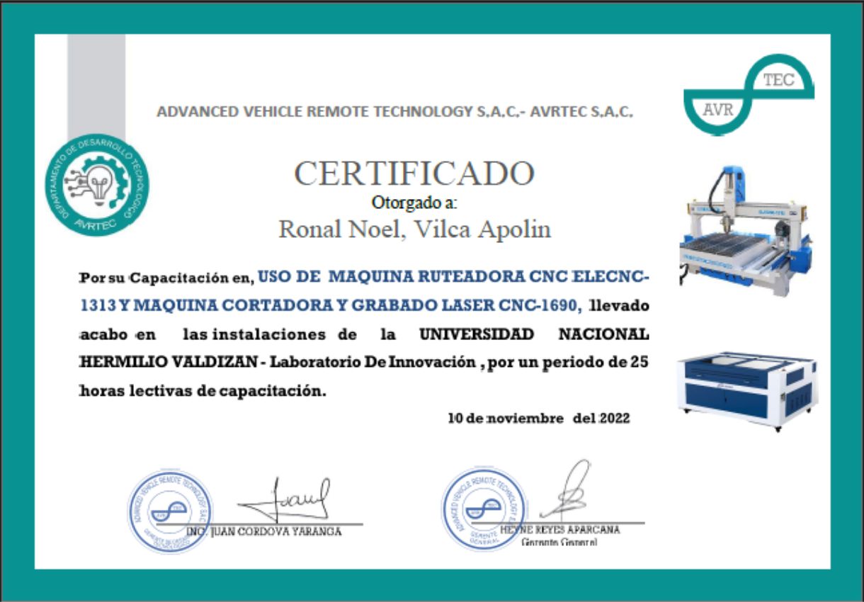
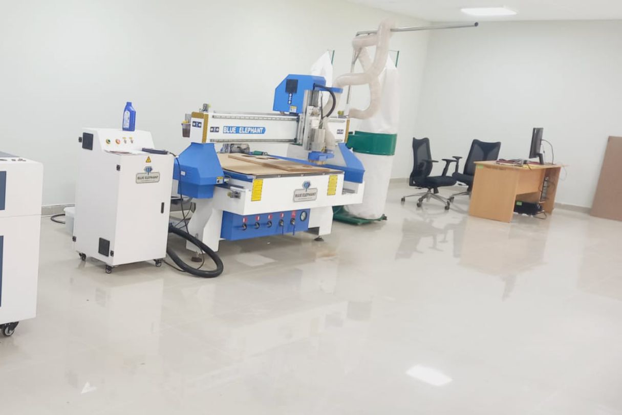
Describing the 1313 4 Axis CNC Router with Rotary Device
The Unheval Fablab is in the implementation process for which one of the machines it acquired is the Blue Elephant brand.
Characteristics:
- Designed with rotary device, it can process the cylinder wood carving patterns, furniture legs, escalators, etc.
- With the heavy duty thicker and bigger welded steel tube frame, it makes the machine work more stably.
- Adopting Japan OMRON limit switch, which ensure the machine with a longer service life.
- With a small footprint and it is more flexible and convenient to use.
- Model: ELECNC-1313
- Effective Working area: 1300*1300*500mm(optional)
- Spindle: 2.2kw
- Spindle speed: 0 - 24000 RPM
- Cooling system: Water mist cooling system
- Software systerm: Artcam Software
- Cooling system: Water mist cooling system
- Voltage: 220v 60HZ
Fablab UNHEVAL CNC Router.
As a team we make comparisons about how our machine works, in my case I asked for support from colleagues who are in other cities in Lima specifically, they shared with me the pattern they managed for the inserts.
As part of teamwork, we make comparisons on how our machine works. In my case, I requested support from colleagues located in other cities, specifically in Lima. They shared the patterns they used for the ensembles with me through an online connection.
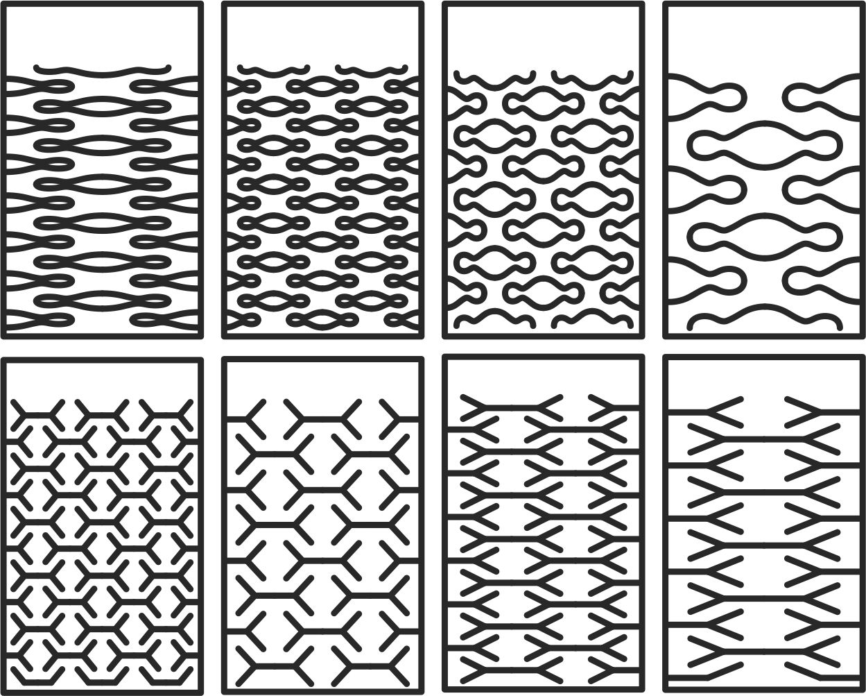
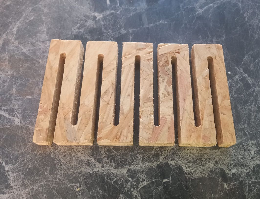
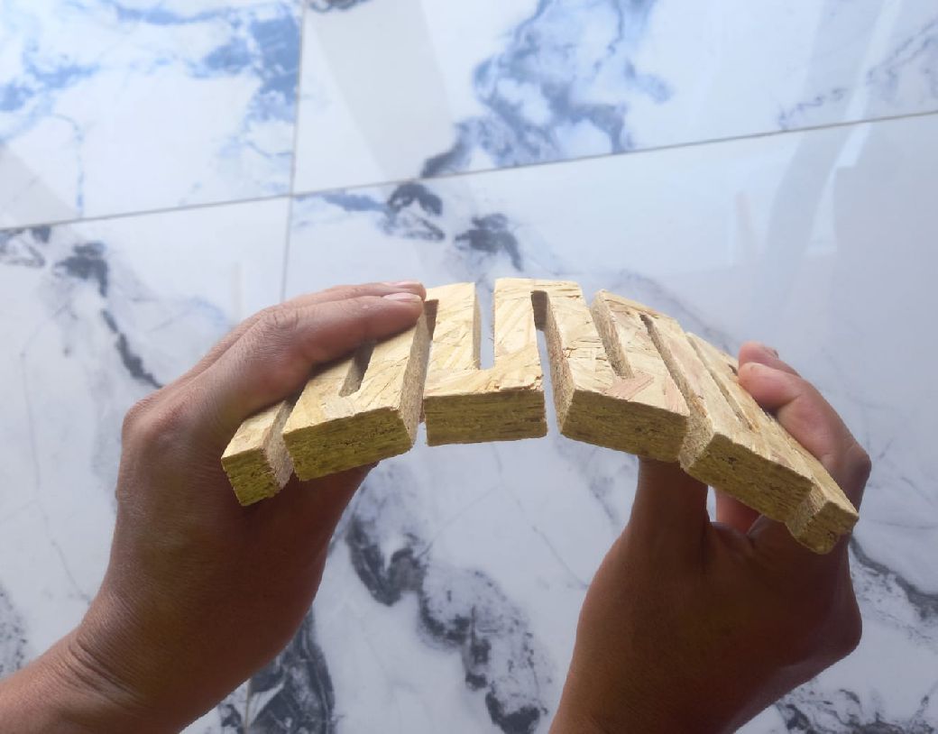
Test vectors for cnc machine.
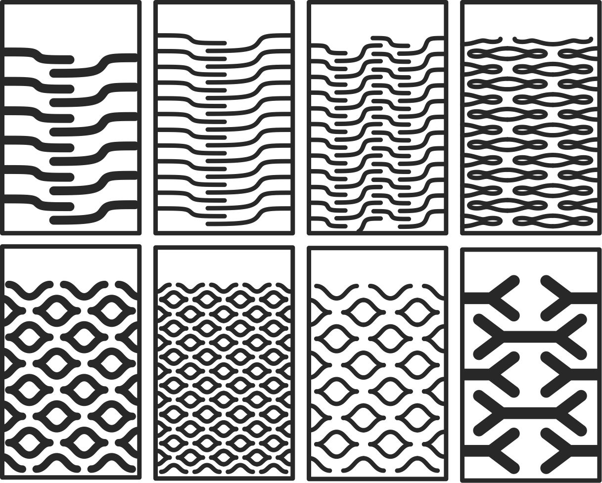
As you can see, this is the test carried out with 15 mm OSB material. Its flexibility is clearly noticeable.
What I learned from teamwork
During this week, I have learned the importance of teamwork and collaboration between all members. This becomes crucial, especially when calculating sockets, as an incorrect calculation can result in the inability to fit the pieces together, as I experienced in one of my tests. In addition, I understood the relevance of clearances and the consideration of the type of material we work with. Each material has to be worked with different characteristics in terms of cutting speed, roughing and working depth, which significantly affects the process. Always keep safety in mind as it is paramount, 'safety comes first', and it is essential to apply common sense at all times."