Week 8. Electronics Design
Group assignment:
- Use the test equipment in your lab to observe the operation of a microcontroller circuit board (as a minimum, you should demonstrate the use of a multimeter and oscilloscope).
- Document your work on the group work page and reflect what you learned on your individual page.
Individual assignments:
- Use an EDA tool to design a development board to interact and communicate with an embedded microcontroller.
Useful links
Group Assignment
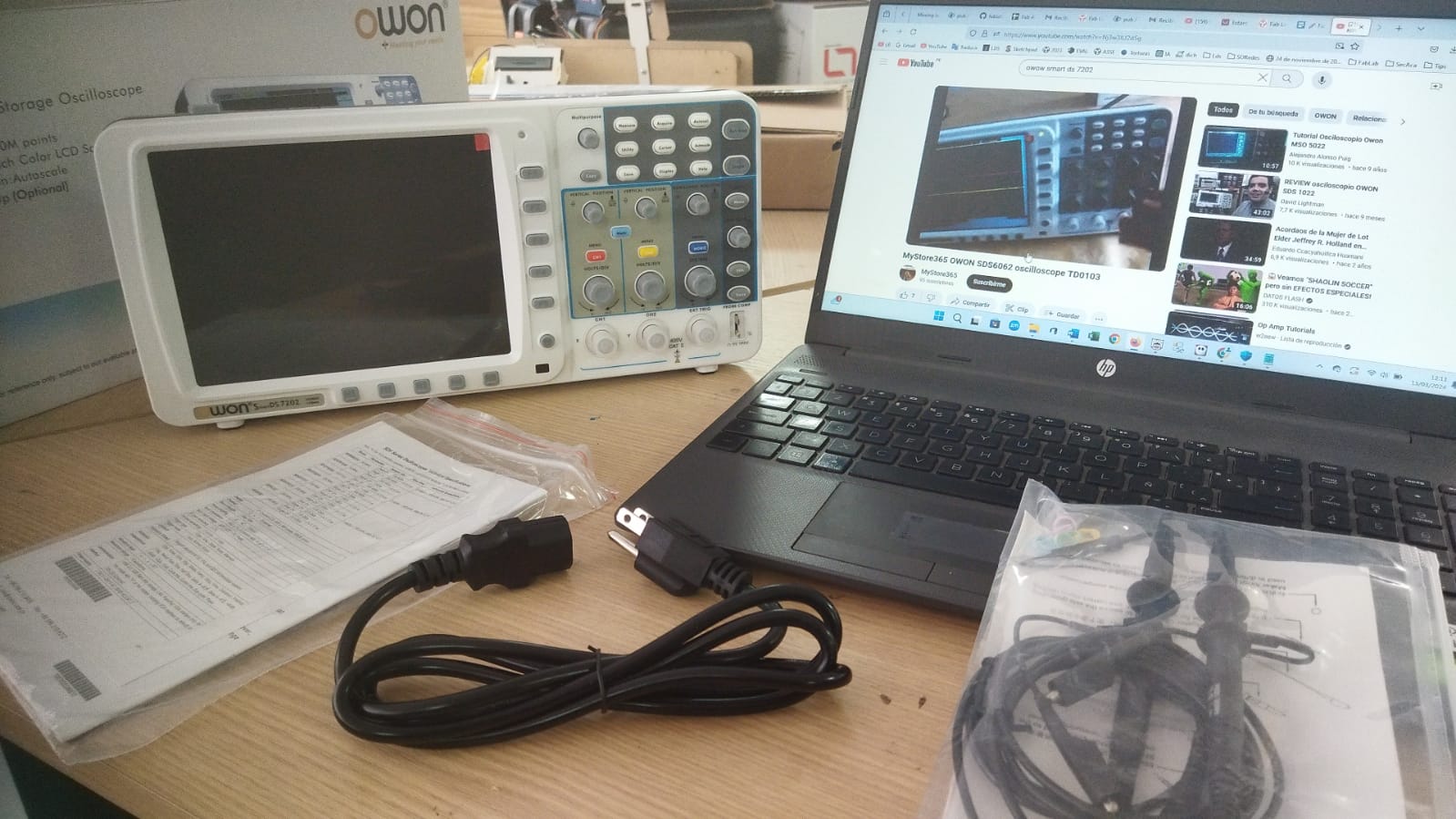
In this group work from Cerro de Pasco we met with my colleague Renso and from the city of Huánuco with our colleague Ronal via Google Meet, to be able to interact and compare the operation of the oscilloscope, which in our case is the WON SmartDS 7202.
Owon SDS7202 Series SmartDS Deep Memory Digital Storage Oscilloscope with VGA Interface, 2 Channels, 60 MHz, 500 MS/s Sample Rate. Features:
- Two-channel 60 MHz digital oscilloscope, for electronic applications such as product design and debugging, repair and maintenance, and electrical engineering education
- Maximum real-time sampling rate of 250 MS/s per channel and record length of 10 Mpts per channel to acquire and process detailed waveforms
- Advanced triggers allow isolation of specific signals and a trigger hold function stabilizes triggering on complex waveforms
- Three math functions plus FFT and 20 automatic measurements to analyze waveforms
- 8” color TFT-LCD for viewing waveforms and a VGA port for connecting to an external monitor.
Digital Multimeter S-75
Features. 1. Maximum voltage: 500vdc or 500vac 2. Protection Fuse: 200ma/250v 3. Power:9vdc 4. Display:LCD.1999counts,Lighting 5. Measurement method: A/D double slope integration 6. Operating Environment :0°C TO 40°C 7. Battery indicator: appears on the screen 8. Measurements: 31.5mm x 91mm x 189mm 9. Weight:approx.280g
Tests with the Oscilloscope
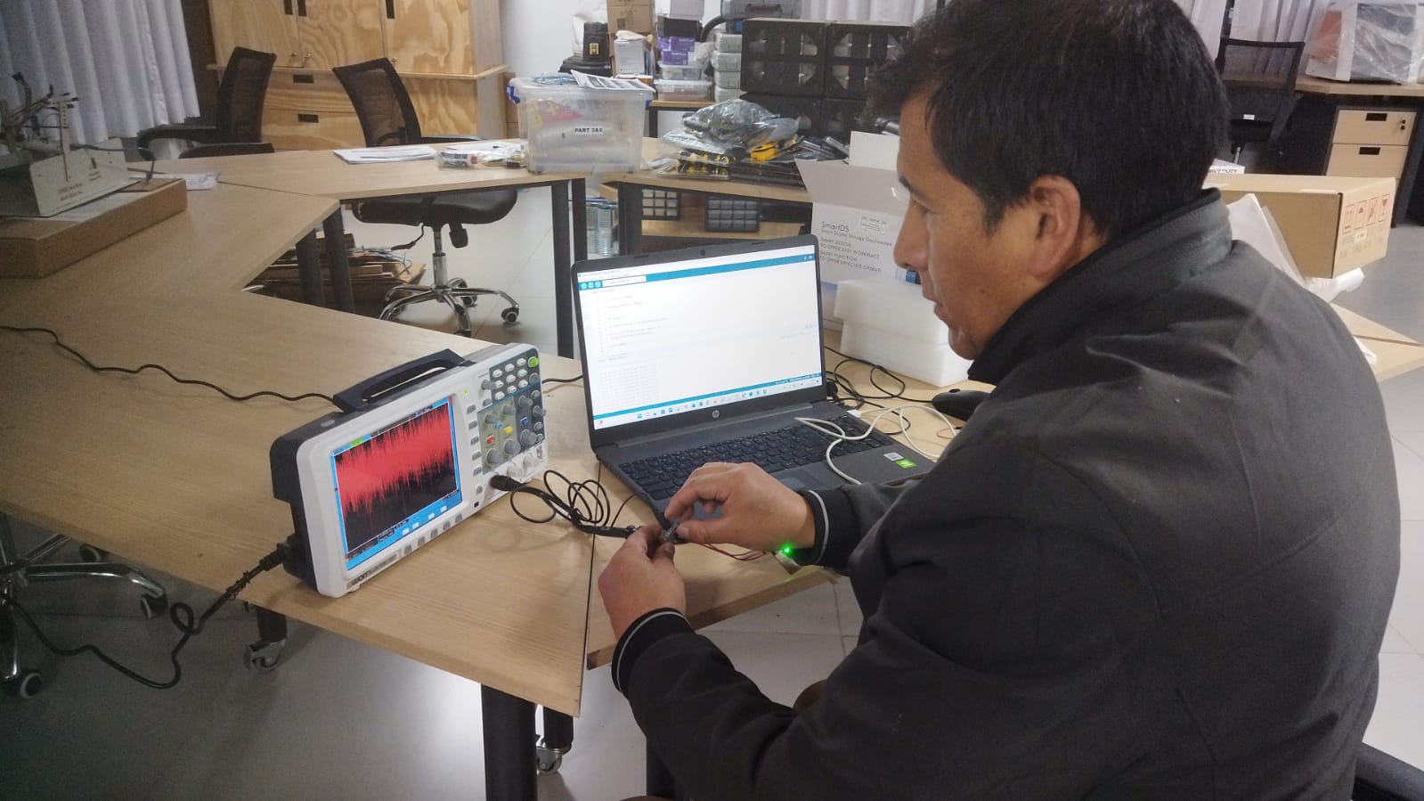
 Teamwork using oscilloscope.
 Preparing the equipment to launch.
 Pressing the power button.
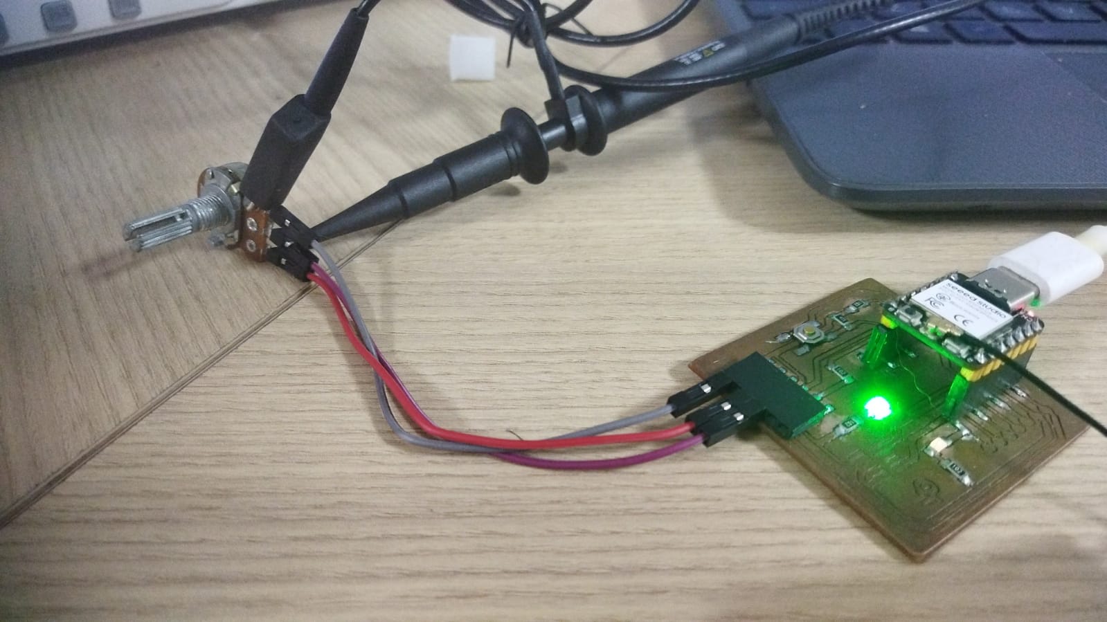 Connecting the tips of the oscilloscope to the ground and signal terminals of the board.
 Setting the signal amplitude button
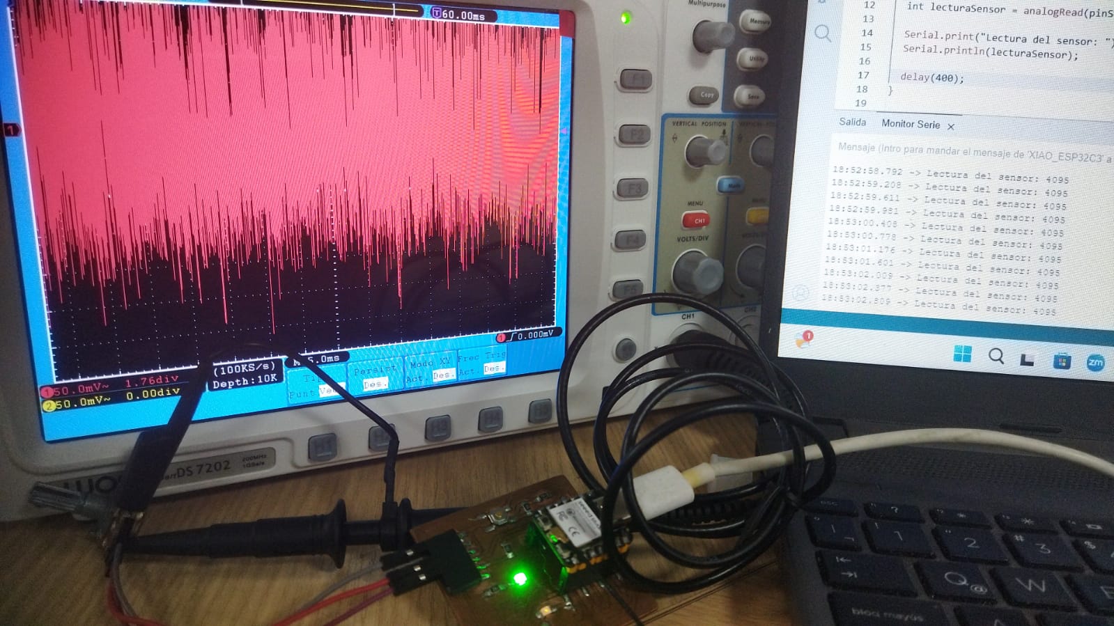
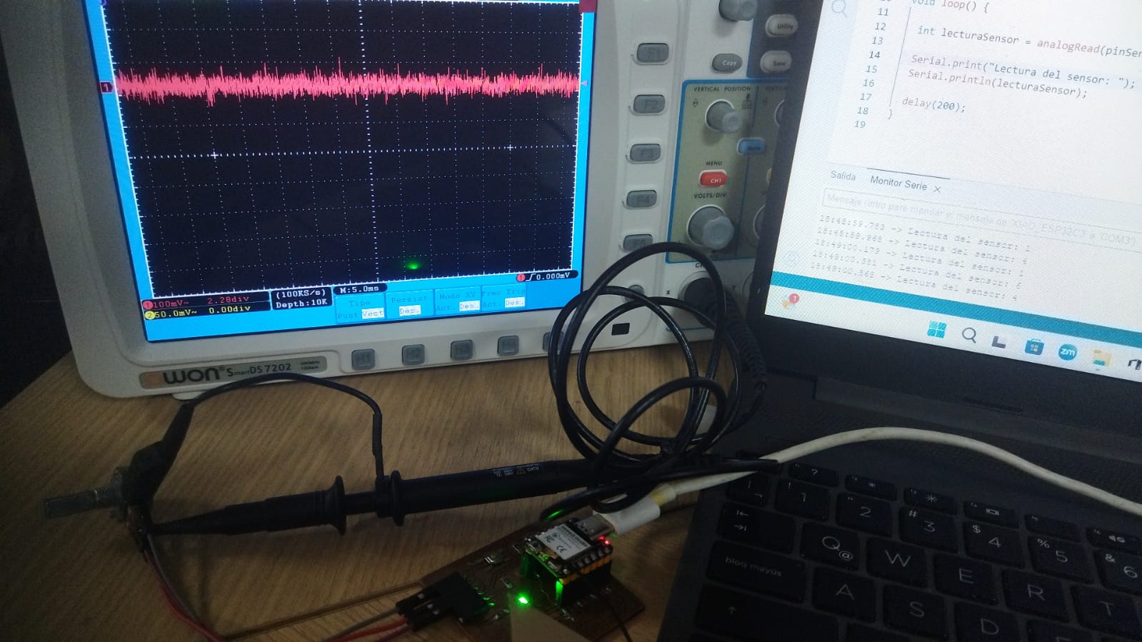 Viewing the signal on the oscilloscope on channel 1 when the potentiometer is at its low value.
 Increasing the value of the potentiometer by half.
 When the potentiometer is increased to the maximum value.
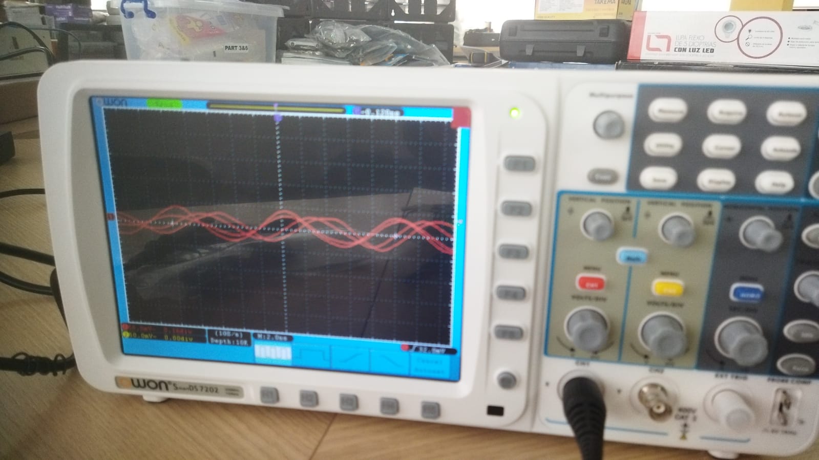 Shows when the signal is expanded.
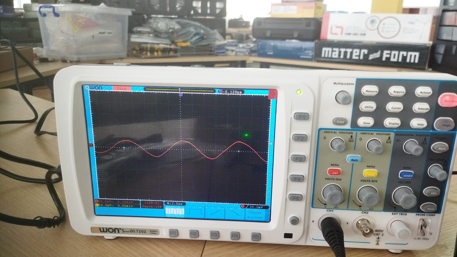 Configuring so that the signal is cleaner with a low potentiometer.
 Configuring so that the signal is cleaner with a high potentiometer.
Tests with the Multimeter
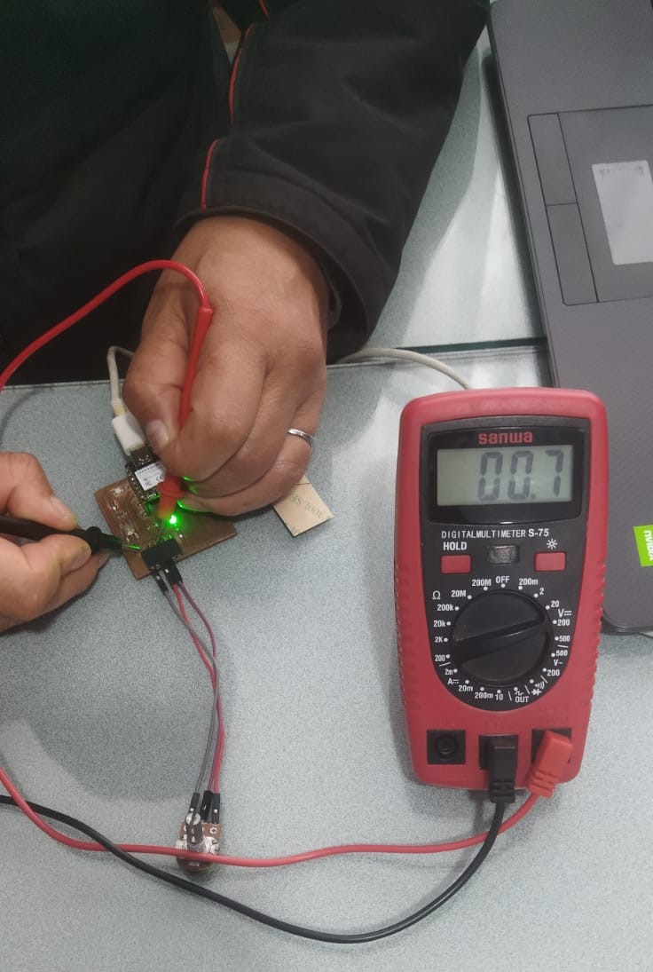
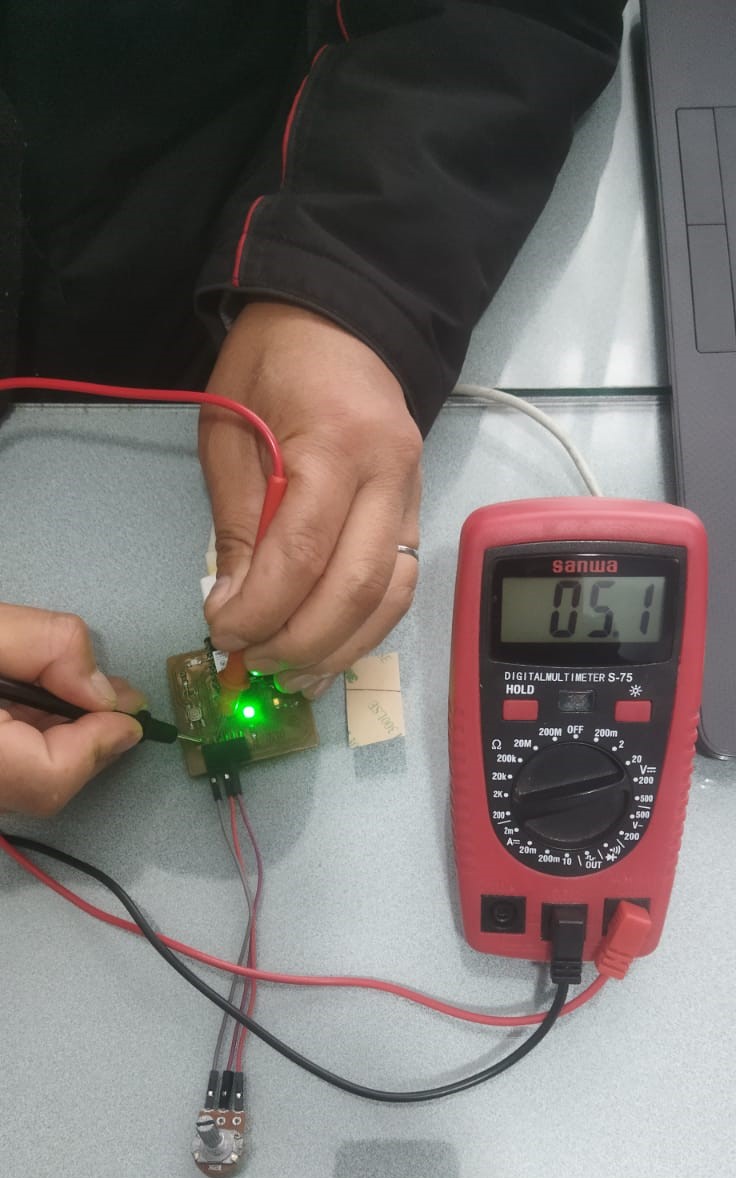 Measuring the five volt power entering the potentiometer.
 Measuring the output of the potentiometer when it is raised to ten percent of its value
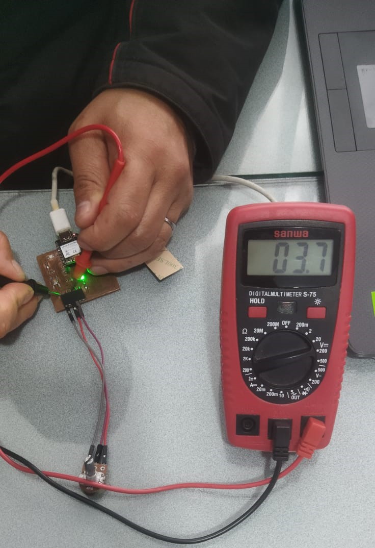 This is what it measured when the potentiometer value was raised to eighty percent.
Individual Assignment
 Choosing the free program to enter the world of electronic circuit designs.
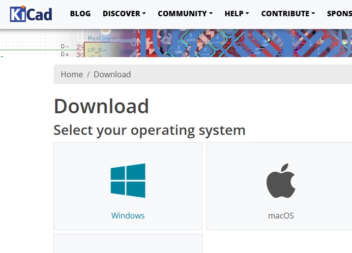 Selecting the platform where to install the Kicad program, in this case on the Windows operating system.
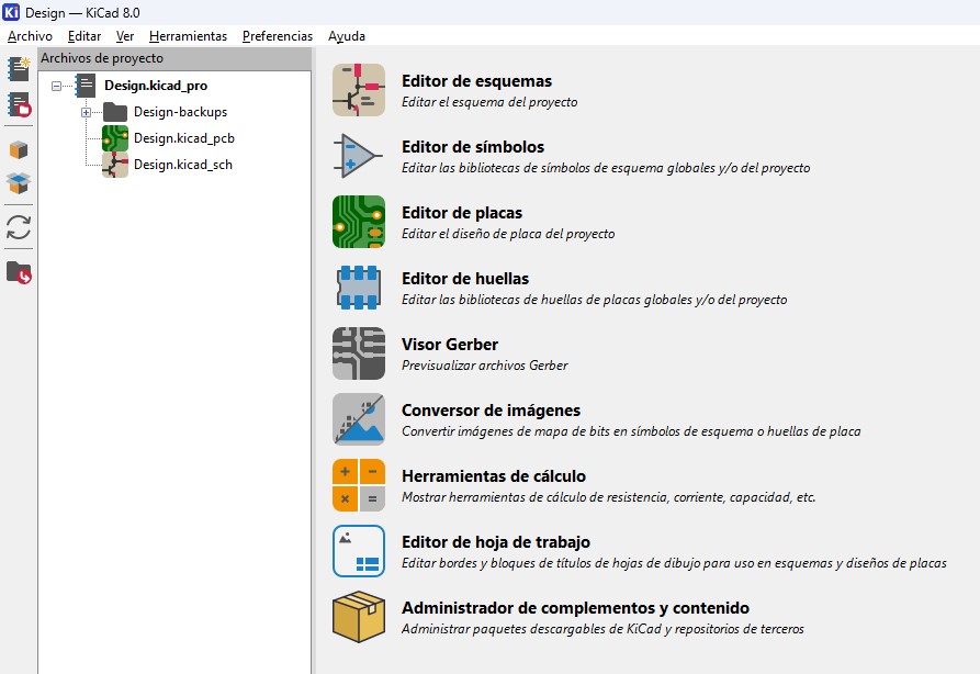
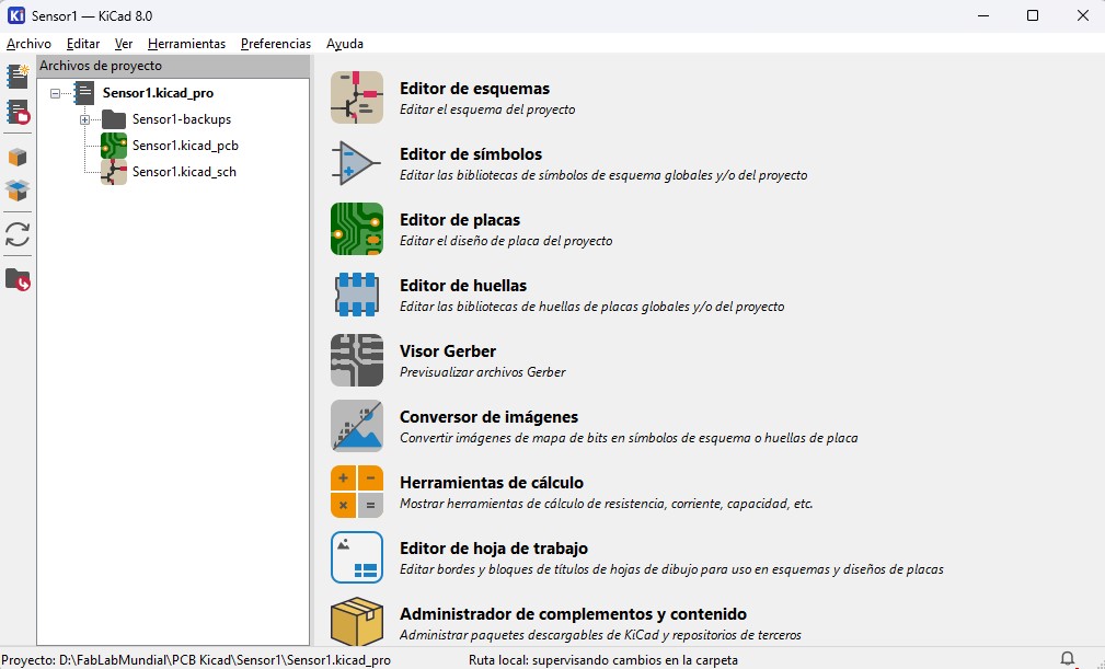 We observe the environment of the Kicad program as soon as it finishes loading.
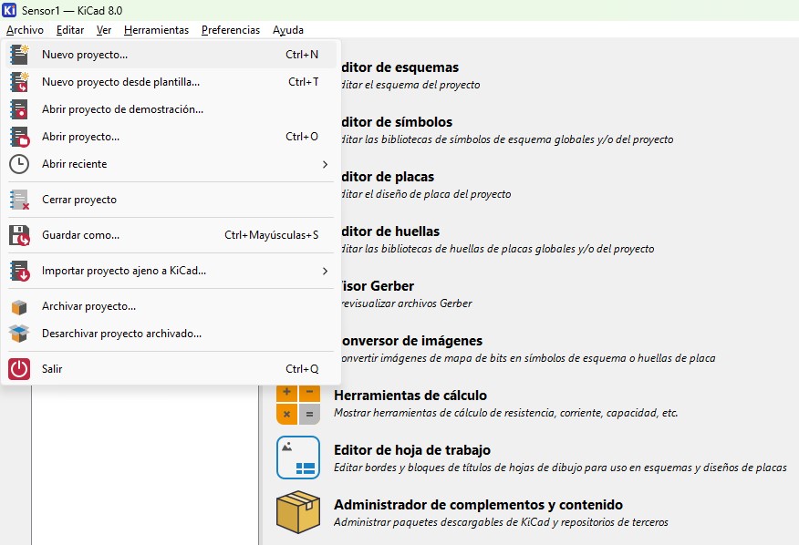 We choose a new project to begin the following processes.
 We choose the drive where the folder to save the new project will be created.
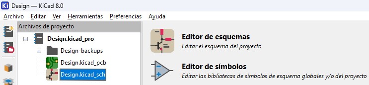
 Here we can see the two files that were created PCB that the design of the card and SCH where the schematic will be developed.
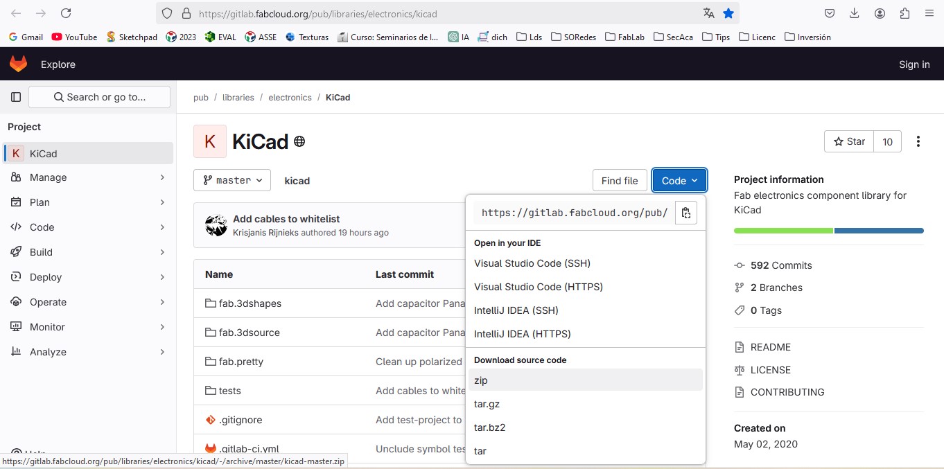 From Github download the library in zip format of the electronic components to be used for the fabacademy.
 From the screen shown we choose symbol editor to install the previously downloaded library
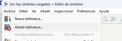 We choose File and then add library
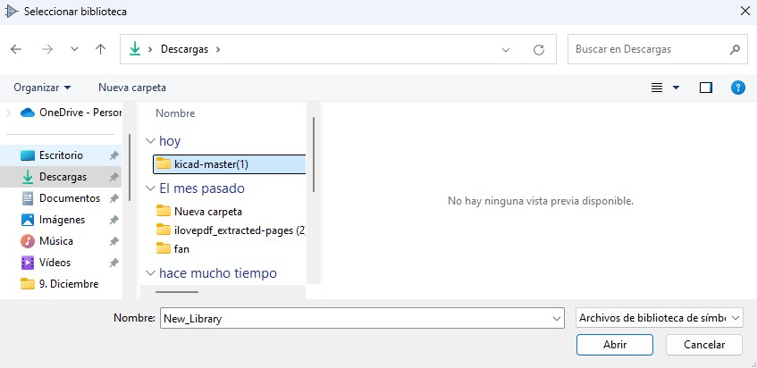 We search and choose the folder where the downloaded library was unzipped
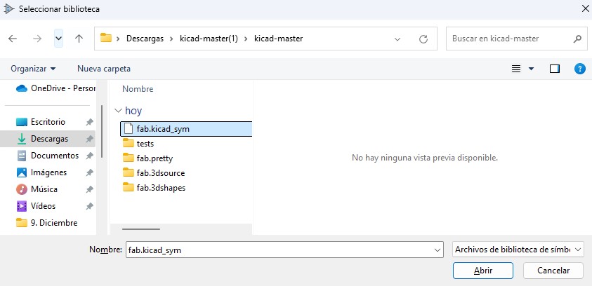 In the unzipped folder, we choose the file that contains the traces of the components to add to the library.
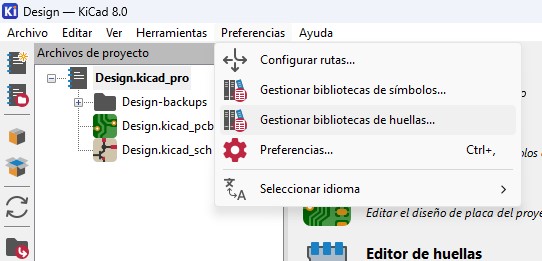 Now we need to choose manage fingerprint library from preferences.
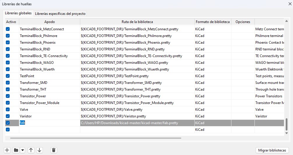 We choose the + sign and then we add a nickname and select the folder where fab.pretty is located
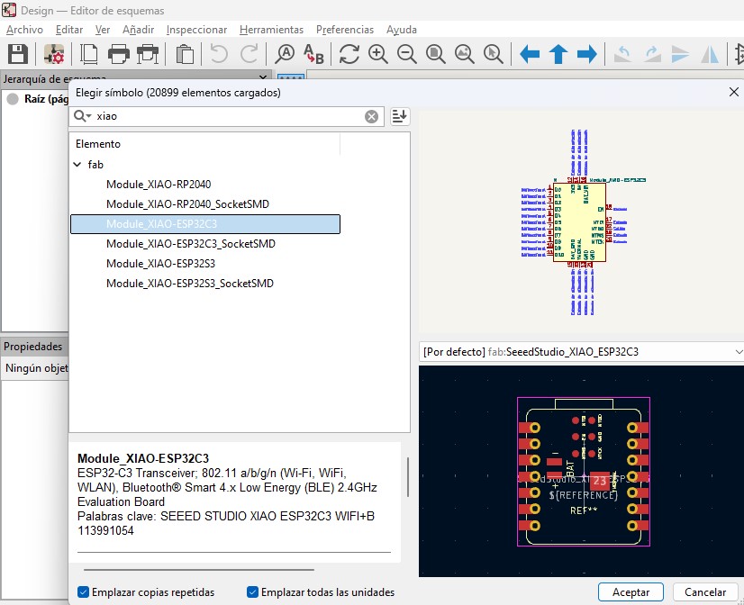 Now in the schematic we choose to add components and look for xiao, which is the microcontroller we are going to work with and we can see that we have it ready.