Electronic Design
Week 8
Group assignment:
- Use the test equipment in your lab to observe the operation of a microcontroller circuit board
- Send a PCB out to a board house
Group 1
Group 2
Group 3
Group 4
Group 1:
- Hans Moncca
- Maryori Vasquez

TEST EQUIPMENT
FAB LAB UCSUR IMPLEMENTS
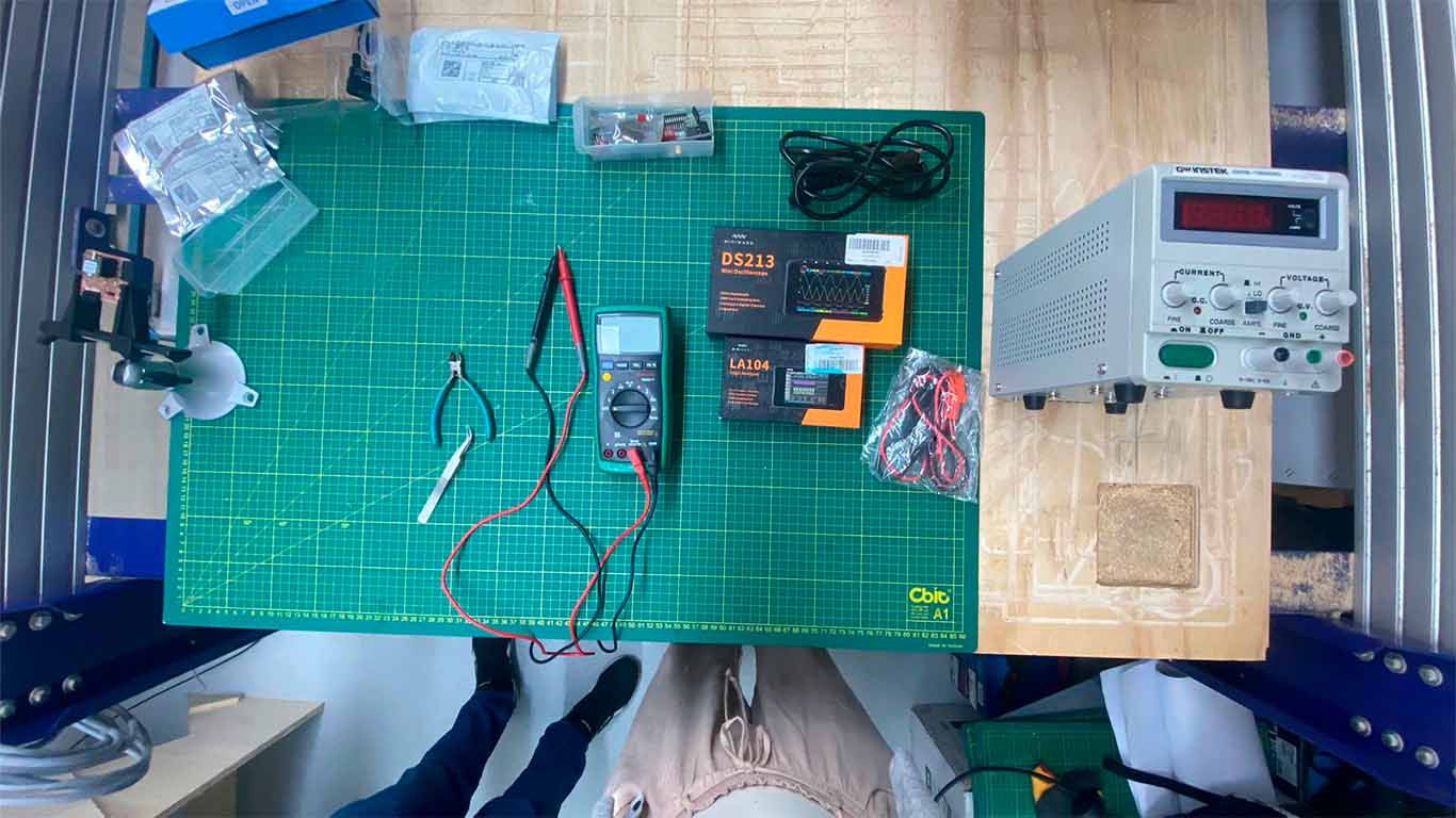
In the FAB LAB UCSUR we have the following components to be able to carry out the following group assignment: MULTIMETER, LOGIC ANALYZER, MINI OSCILLOSCOPE and DC VOLTAGE SUPPLY. In the next section I will explain how we performed the test with all these instruments at QUENTORRES.
TESTING WITH MULTIMETER
To understand the use of the multimeter, we will first test the components alone and then apply it to the QUENTORRES board developed in week 4 of ELECTRONIC PRODUCTION. First we will start to see the polarity of 2 types of LEDS, the first will be the DIP LED and then the SMD LED
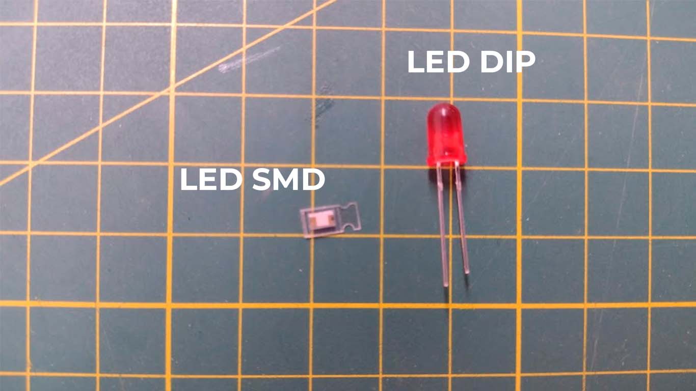
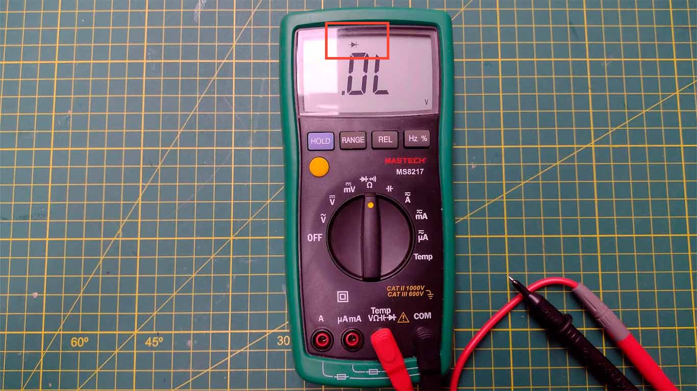
What we have to take into account is knowing which of the poles of each LED is negative or positive. In the DIP LED, the negative is always the one that is shorter and the other is positive. On the other hand, in the SMD LED, there is a green mark that the component has, the side where it is located on the LED is the negative pole and the other is the positive pole. On the multimeter, we have to choose the "DIODE TEST" option that has the logo marked in the photograph. This will help us see if the LEDs are working correctly.
Now here I show the test that we carried out with the SMD LED, where we can see that its polarity works and it can be turned on with our multimeter.

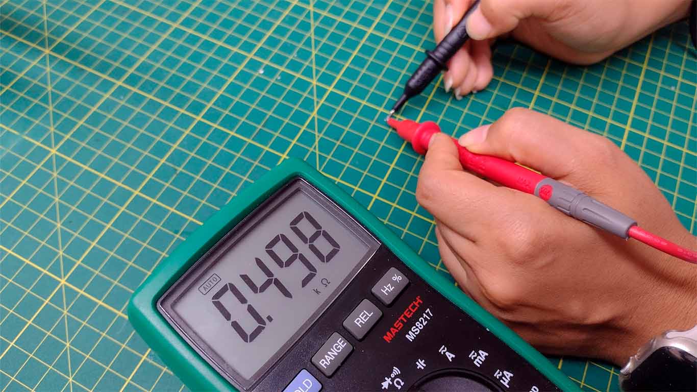
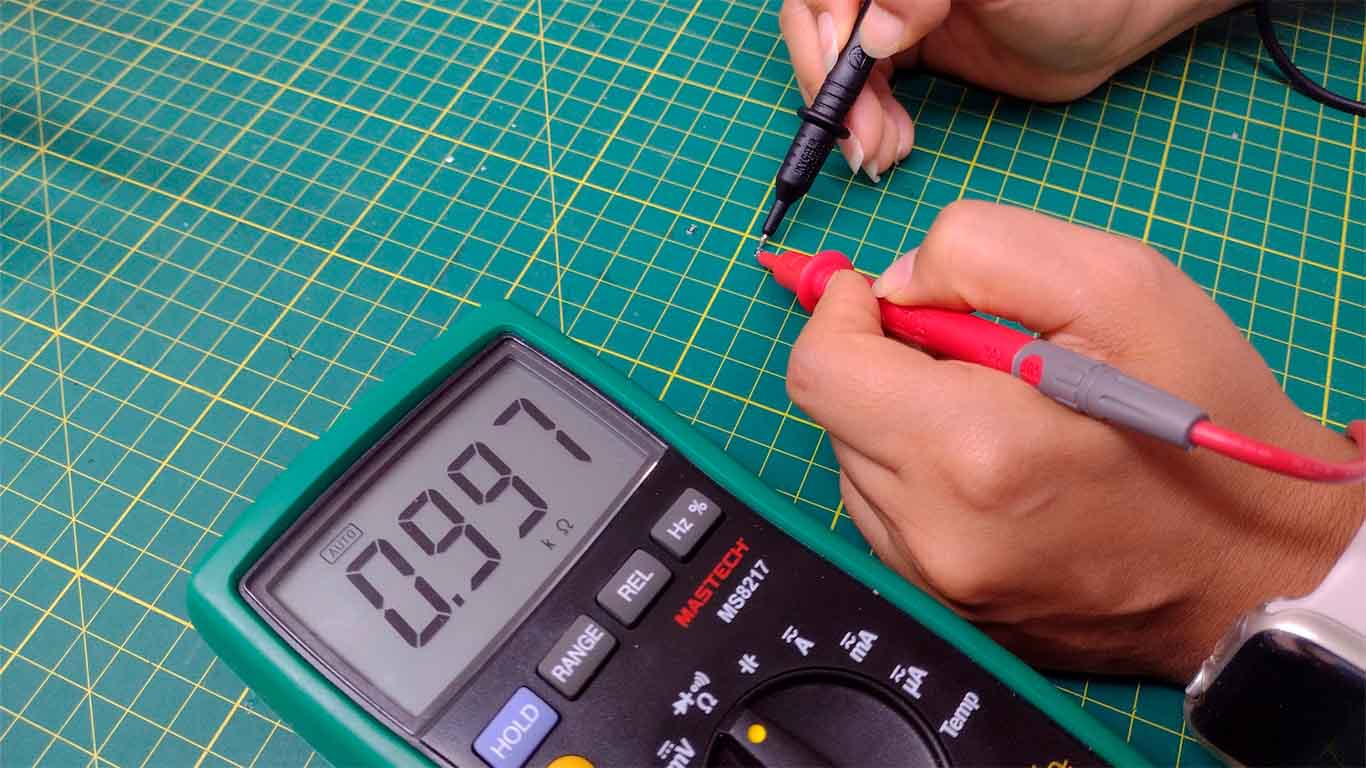
Now we will try with our resistors that we found in our FAB LAB. Here we will see the resistance that each one presents and the value they have according to the multimeter. To know how much resistance our components have, we have to go to the multimeter and choose the "Ω" symbol that means resistance, with this we can calculate it. Here our group tests.

For the test with the SMD resistors, we will use the 499 and 1K resistors, which will be tested by the multimeter to corroborate their value and we can see the resistance it presents.
Now we will perform the CONTINUITY test in the QUENTORRES developed in week 4 of the FAB ACADEMY. Here we can see that the TRACES must have continuity and must be checked with the use of the multimeter. When the multimeter chooses the CONTINUITY symbol, it will emit a sound confirming that there is continuity, but if it does not emit it, it means that there is no continuity and the components are not connected.

TESTING WITH LOGIC ANALYZER
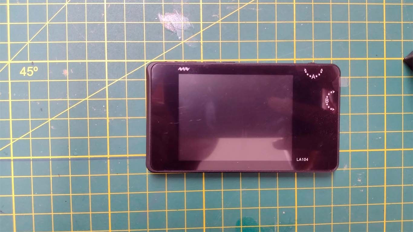
The logic analyzer that we have at the FAB LAB UCSUR is the LA104. Before starting to use it, they recommended that we calibrate it and configure it to start using it in the QUENTORRES. Likewise, we learned its management, configuration and how to interpret its data in order to analyze the behavior of digital signals. Here are some photos before using it.

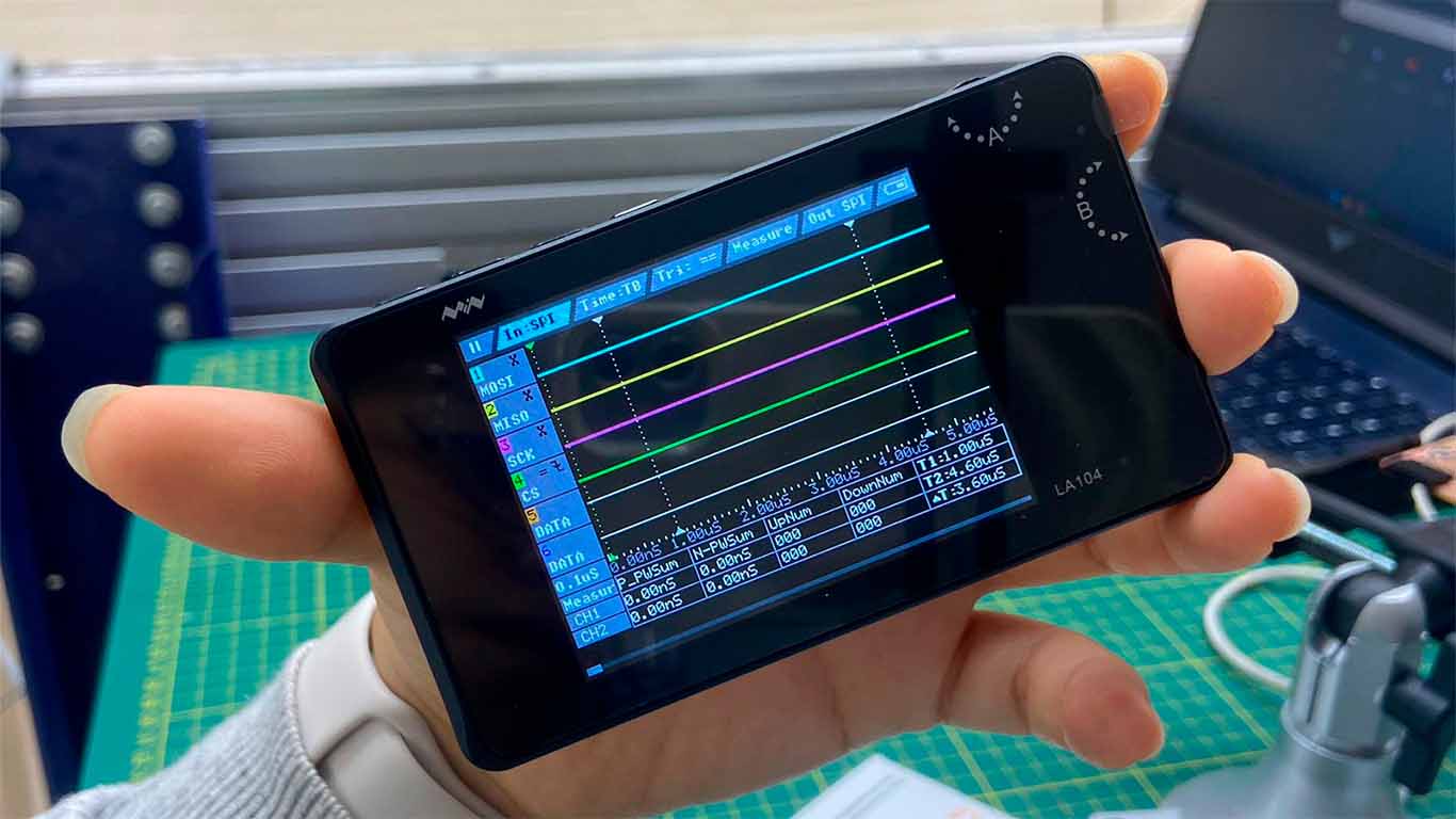

For the test with the logic analyzer, connect the GND and Channel 1 to the Quentorres board to know the graphic representation that we have when we perform the test.
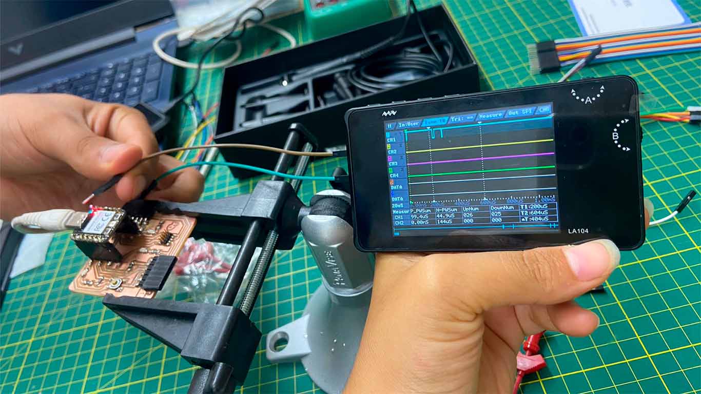
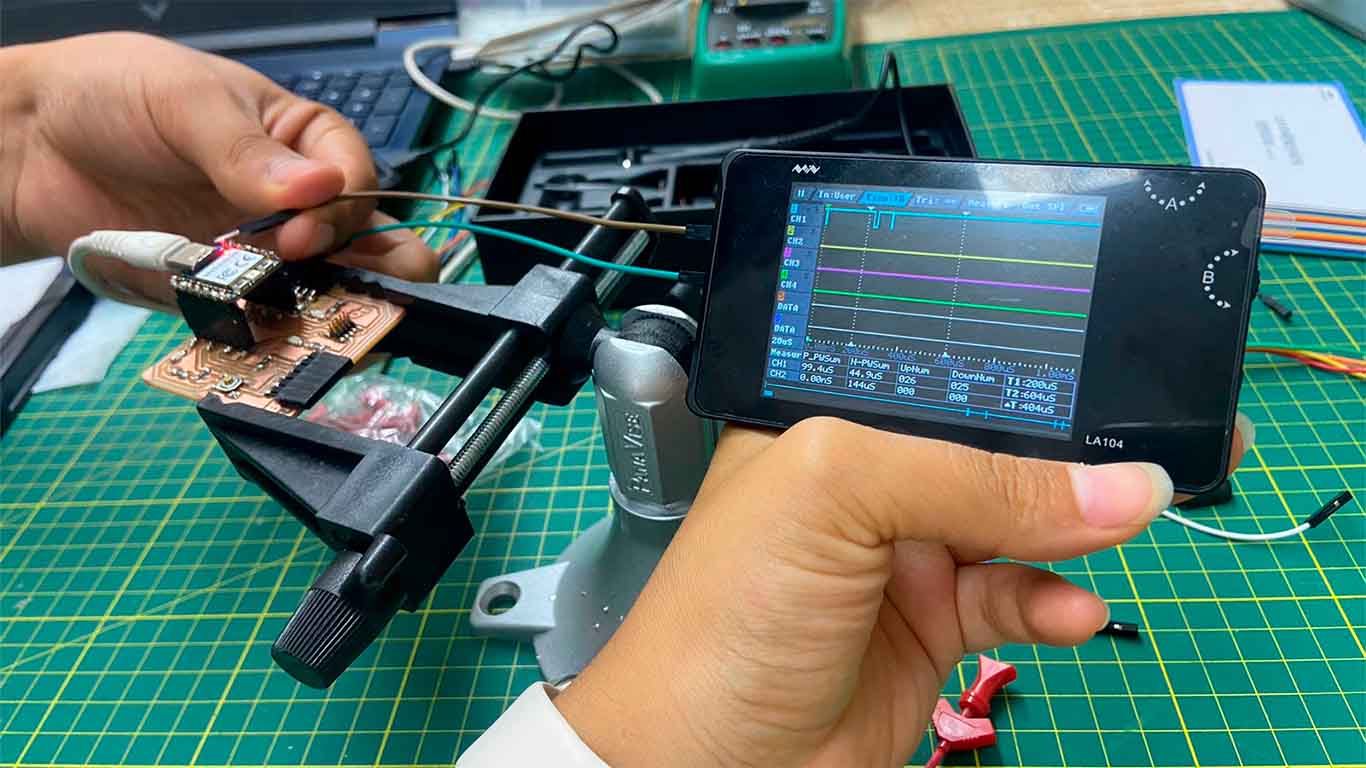
As a result we obtain square signals on channel 1, where we can conclude that the QUENTORRES sends binary digital signals when we make contact with one of its pins and where we can see the communication protocol it is doing.
TESTING WITH MINI OSCILLOSCOPE
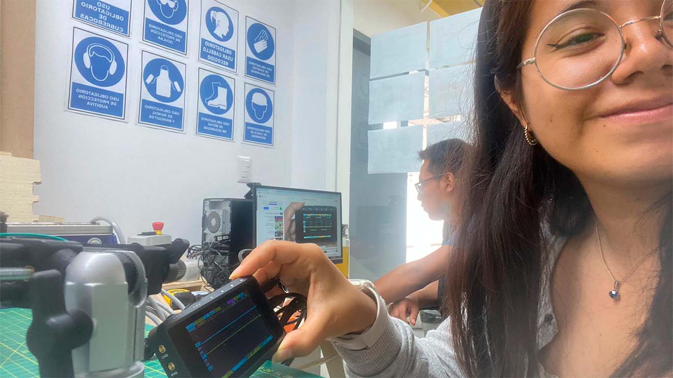
Now we will use the MINI OSCILLOSCOPE that we have in the FAB LAB. We will also try it on the QUENTORRES plate. My friend Maryori gave me this selfie that I didn't realize she took because we were watching videos, some previous documentation to know how it is used and how we can analyze the plate with this tool.
After studying the tool more, we applied it in the QUENTORRES where we were able to know, visualize and analyze the electrical signals of the board when we make contact with it. The truth is that it is very interesting to know how the different behaviors that the components have are shown and see electrical signals. Here are some photographs we took when performing the test.
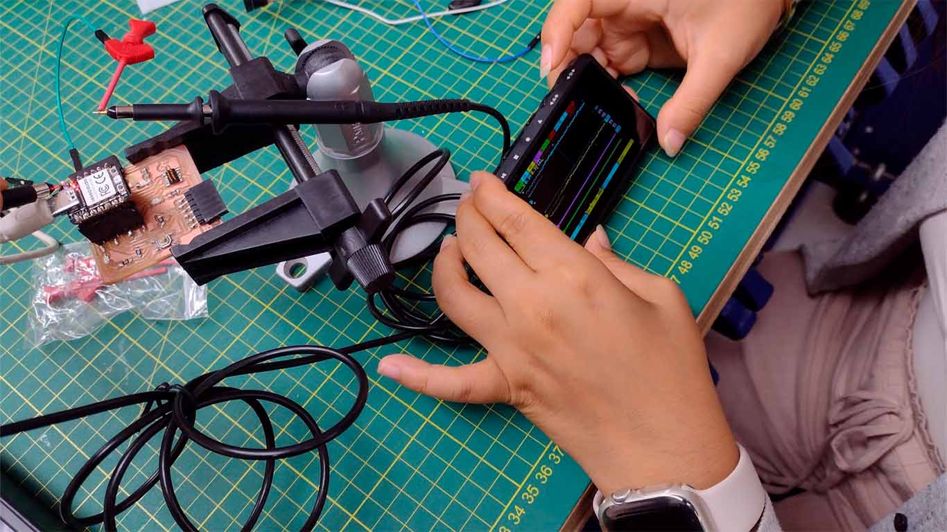
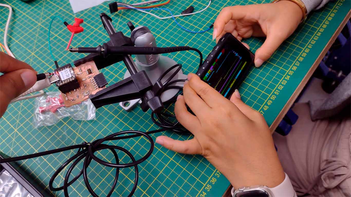
As a result of the tests applied to the QUENTORRES we obtain sine waves which means that the board provides AC alternating current signals generated by the components found on the board.
TESTING WITH DC VOLTAGE SUPPLY
For the test with the voltage supply we perform it with a servomotor to know its operation. First we understood the parts of the machine and then we connected it with the servomotor on their respective positive and negative pins.

Connect the servomotor cables with the voltage supply machine using hooks.


Group 2:
- Cristian Loayza
- Silvana Espinoza
- Maria Angela Mejia
- Jesus Lucero
- Jose Alberto Rodriguez
Test Equipment
To use the oscilloscope and multimeter -as a team- we went to IEST Simon Bolivar Fab Lab which is located in Bellavista district in Callao, Peru.
Using the Oscilloscope
The oscilloscope is a versatile electronic instrument used to visualize and analyze the waveform of electrical signals over time. It displays the amplitude (voltage) of a signal on the vertical axis and time on the horizontal axis, allowing users to observe the shape, frequency, amplitude, and other characteristics of the signal. Oscilloscopes are commonly used in various fields, including electronics, telecommunications, physics, and engineering, for tasks such as troubleshooting circuits, measuring signal integrity, analyzing frequency response, and debugging electronic systems. Modern oscilloscopes often come with advanced features such as digital storage, multiple channels, various trigger options, and built-in signal processing capabilities.
For this task, we used the OWON SmartDS. First, in Arduino IDE we programmed a LED on Quentorres to blink.


Then, we connected the oscilloscope to the GND and D2 pin in XIAO ESP32-C3.


We got triangle waves from bliking programmation in XIAO ESP32-C3.
Usign the Multimeter
The multimeter is a handheld electronic instrument used to measure multiple electrical quantities such as voltage, current, and resistance. It typically consists of a display screen, selection dial, and probes or test leads. Multimeters can be used in various applications, including electronics, automotive diagnostics, electrical engineering, and household tasks. They are versatile tools capable of performing several functions: voltage, current and resistance measurement. Some multimeters also offer additional features such as continuity testing, diode testing, capacitance measurement, and transistor testing. They are essential tools for both professionals and hobbyists in the field of electronics and electrical engineering, providing valuable information for circuit analysis, troubleshooting, and maintenance.
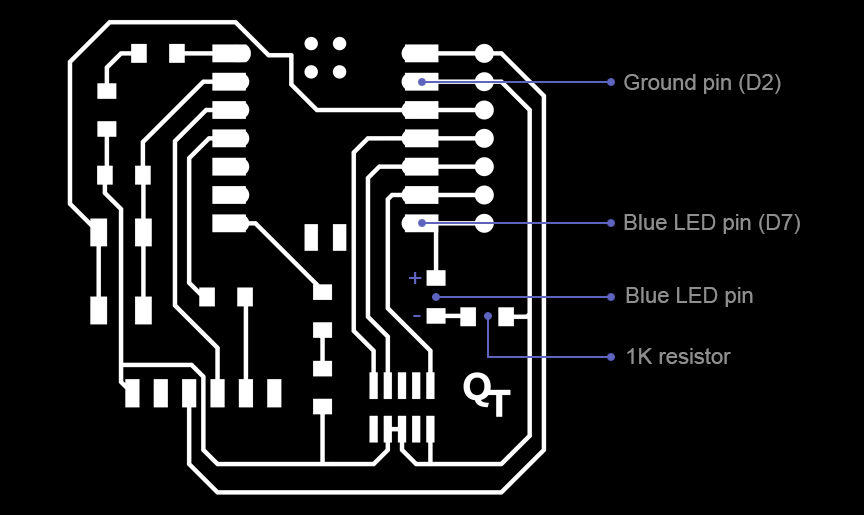
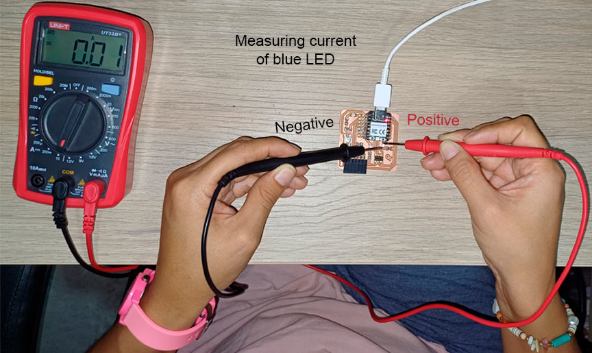
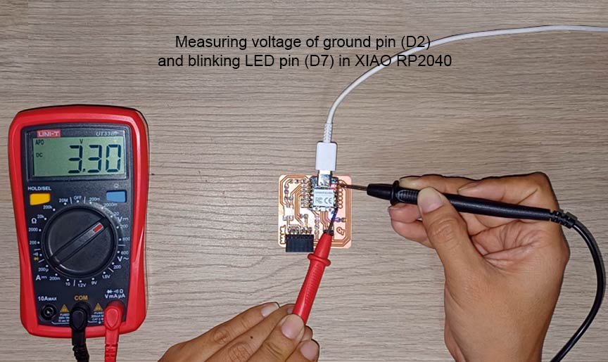
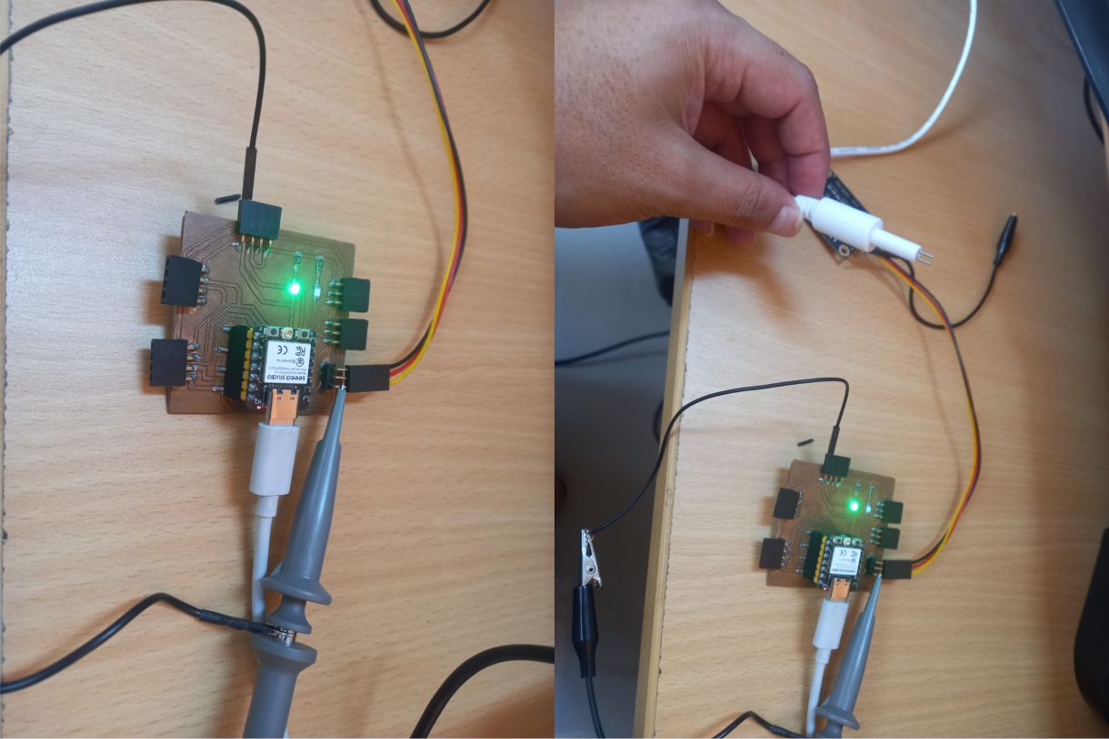
For this task, I used the UT33B+. First, in Arduino IDE I programmed a LED (connected to D7 pin on Quentorres with XIAO RP2040) to blink. Then, I started measuring current of blue LED.
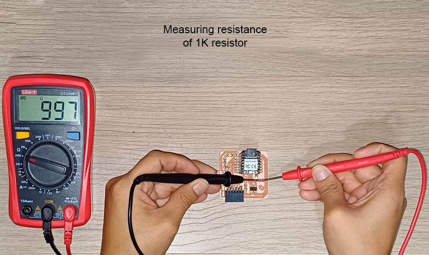
After that, I measured current an resistance of 1K resistor.

Then, I measured resistance of 499 resistor and voltage of blue LED.


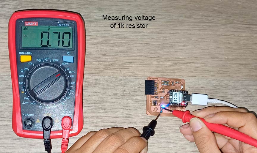
Finally, I measured voltage of 1K resistor and voltage of GND pin and blinking LED in XIAO RP2040.
Conclusions
- The oscilloscope serves as an indispensable tool in electronics, offering real-time visualization and analysis of electrical signals. By displaying voltage waveforms over time, it enables to assess signal characteristics, diagnose circuit issues, verify performance, and debug electronic systems with precision.
- The multimeter stands as an essential tool for electrical measurements. By enabling users to measure voltage, current, resistance, and other electrical quantities, it serves as a fundamental instrument diagnosing faults, testing components, or verifying circuit parameters. With its diverse functionality and ease of use, it plays a pivotal role in circuit analysis, troubleshooting, maintenance, and general electronic tasks.
I especially want to thank Jorge Cabrera for allowing us access to the Simon Bolivar Fab Lab to complete the assignment of this week.

Group 2:
- Renson Samaniego
- Wilber Giron
- Ronal Noel
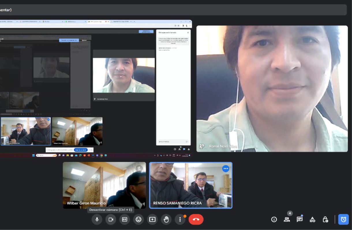
Ronal Vilca Apolin
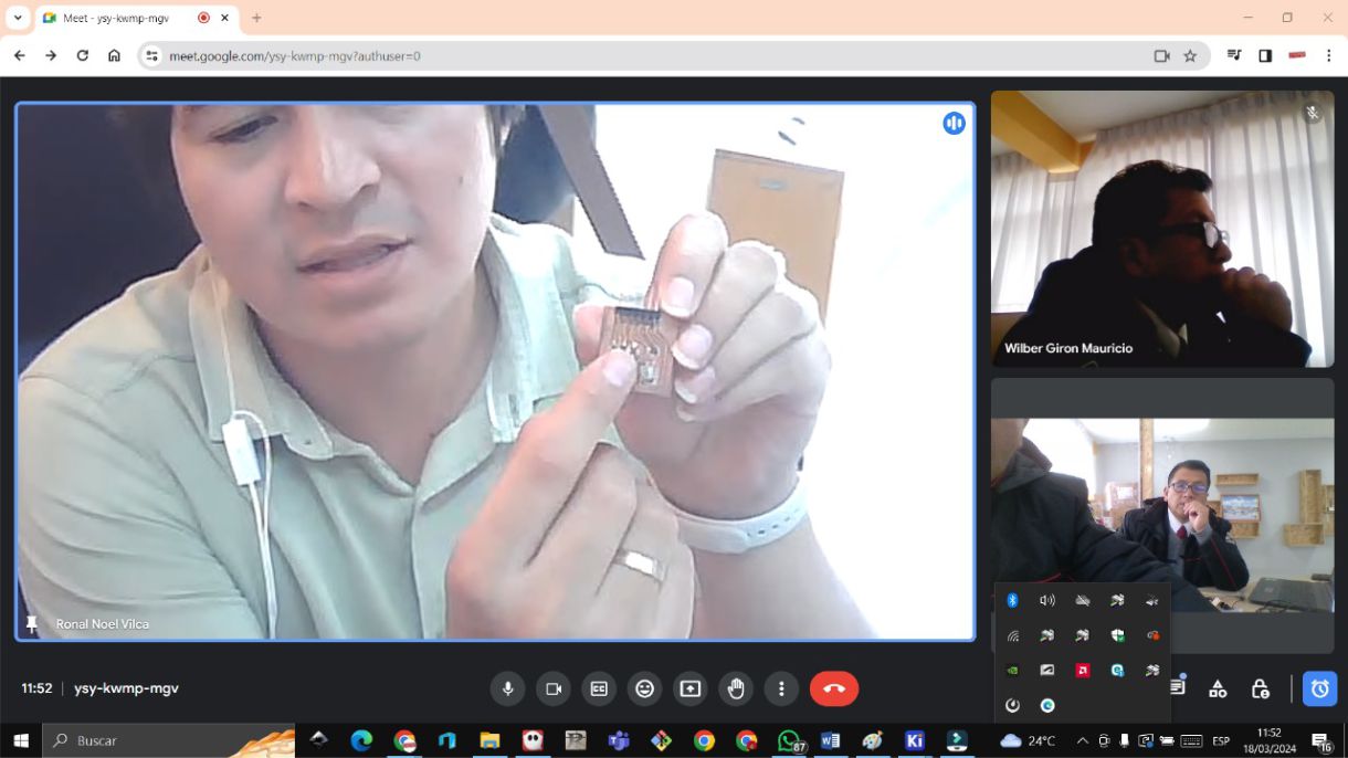
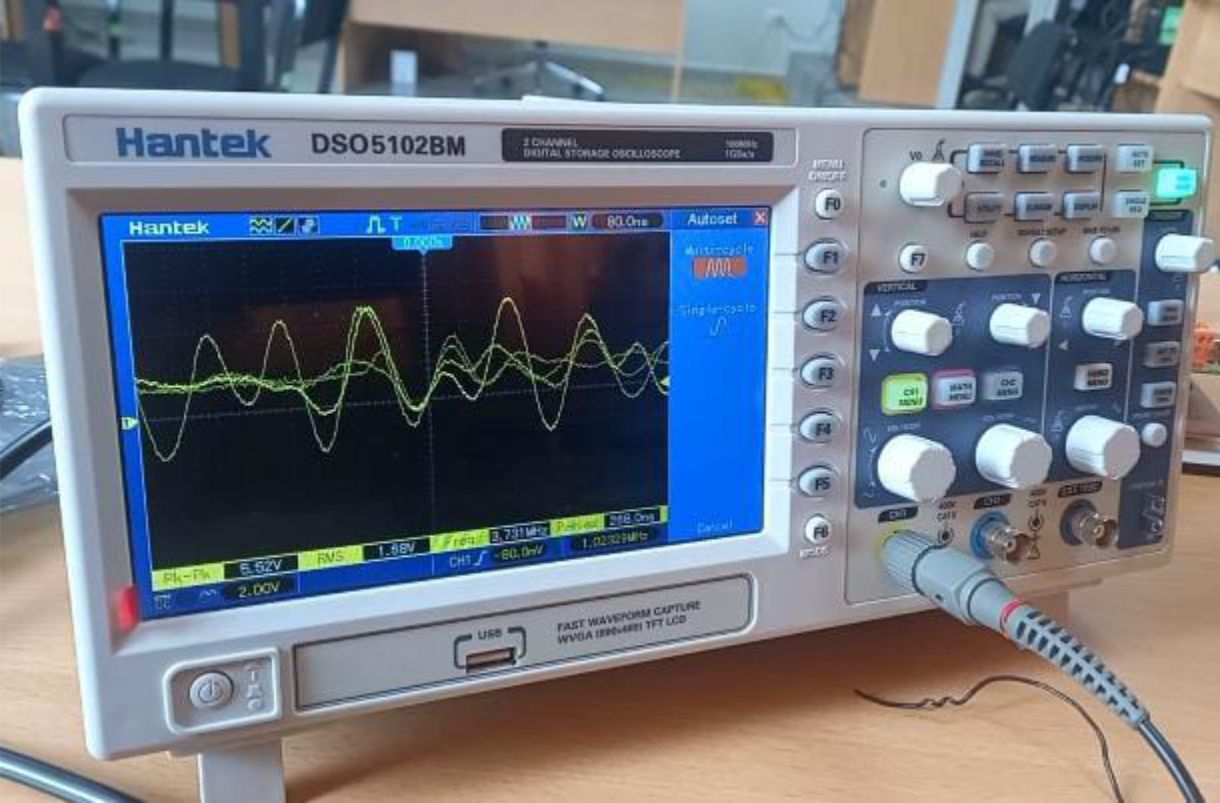
For group work, we met through Google Meet with colleagues Wilber and Renso, who are in the city of Pasco. The objective of the meeting is to perform tests with the oscilloscope. In my case, I use the Hantek DSO5102BM oscilloscope.
Hantek DSO5102BM Osciloscopio Digital 2 canales de mano USB LCD Osciloscopio 100Mhz drilloscopios 2M Longitud de grabación
Features
- 100MHz bandwidths.
- Real time sampling rate 1GSa/s.
- Large color screen (7.0 inches), WVGA(800x480).
- Recording length up to 2M.
- Trigger mode: edge/pulse width/line/slot/overtime selectable video, etc.
- USB host and device connectivity, standard.
- Multiple automatic measurements.
- Four mathematical functions, including standard FFTs.
- Provides software for real-time PC analysis.
- VGA optional.
Fluke 87V Industrial Multimeter
For voltage, resistance and continuity tests, we use the Fluke brand multimeter. It is a piece of equipment of excellent quality and highly recommended for its precision and reliability.
Main features
- True RMS AC voltage and current for accurate measurements for non-linear signals.
- Selectable filter for accurate frequency and voltage measurements in variable speed drives.
- 0.05% DC Accuracy 6000 counts, 3-3/4 digits.
- 4-1/2 digit resolution for accurate measurements (20,000 counts).
- Measurements up to 1000 V AC and DC.
- Measurement up to 10 A; 20 A for a maximum of 30 seconds.
- Integrated thermometer that avoids the need to carry an additional tool (temperature probe included).
- FFrequency up to 200 kHz and duty cycle (in %).
- Resistance, continuity and diode test.
- 10,000 µF capacitance range on motors and components.
- Recording of minimum, maximum and average values with alarm for automatic capture of variations
- Peak capture to record transients as fast as 250 µs
- ll inputs have been updated to the 3rd edition of ANSI/ISA S82.01 and EN61010-1 CAT IV 600V and CAT III, 1000 V. They can withstand impulses greater than 8000 V and reduce risks related to overloads and spikes.
Tests with the Oscilloscope
For the first tests with the multimeter, we use the TDS sensor as input, which measures water quality. I proceeded to connect the clamps, I connected the retractable to the signal input and the alligator to GND.
Yes, square wave type signals can be displayed to take values from the machine and ensure that measurements are correct. In addition, the distorted sine wave type signal from the TDS sensor can be observed to evaluate its behavior and accuracy.
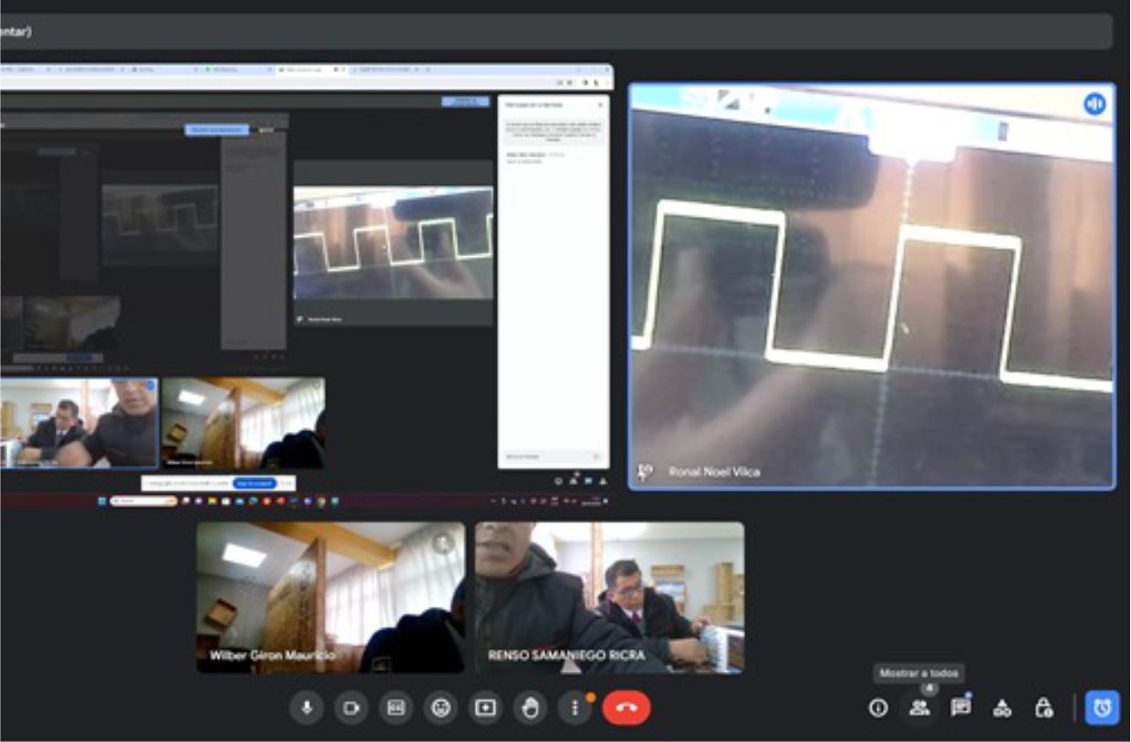
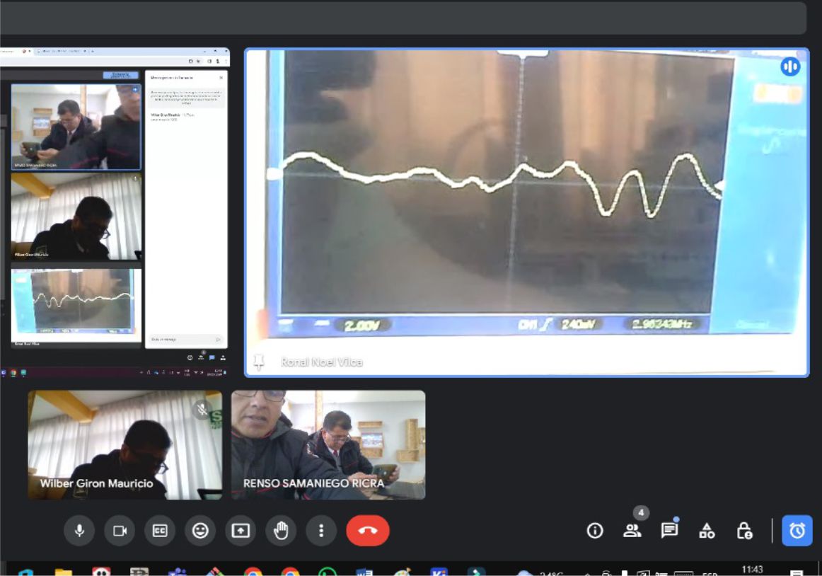
During the discussion with my colleagues, we analyzed the values displayed by the oscilloscope. We use channel 1 and perform automatic calibration to obtain the values and ranges of our sensor. In my case, we observed that the maximum values reached 560mV. To record this data, we clicked on snapshot screenshot
Tests with the Multimeter
To perform measurements, such as resistance, voltage, and continuity testing, we use the test board we developed. In my case, I used an additional extension board that has a push button as input and an RGB LED as output.
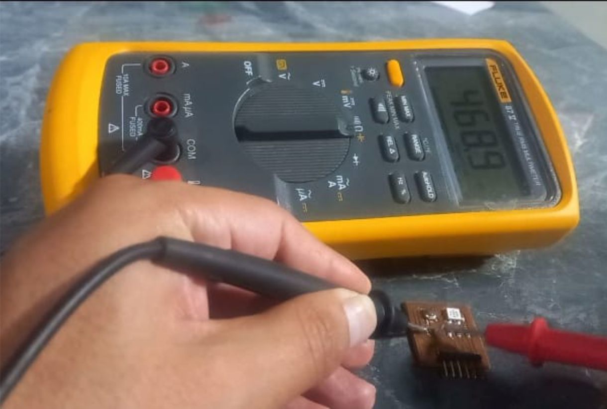
As can be seen in the image, we measure the resistors that we will connect to the anodes of the RGB LED. We use two 150 ohm resistors for colors G and B, and one 100 ohm resistor for color R. We also use a 470 ohm resistor for the push button.
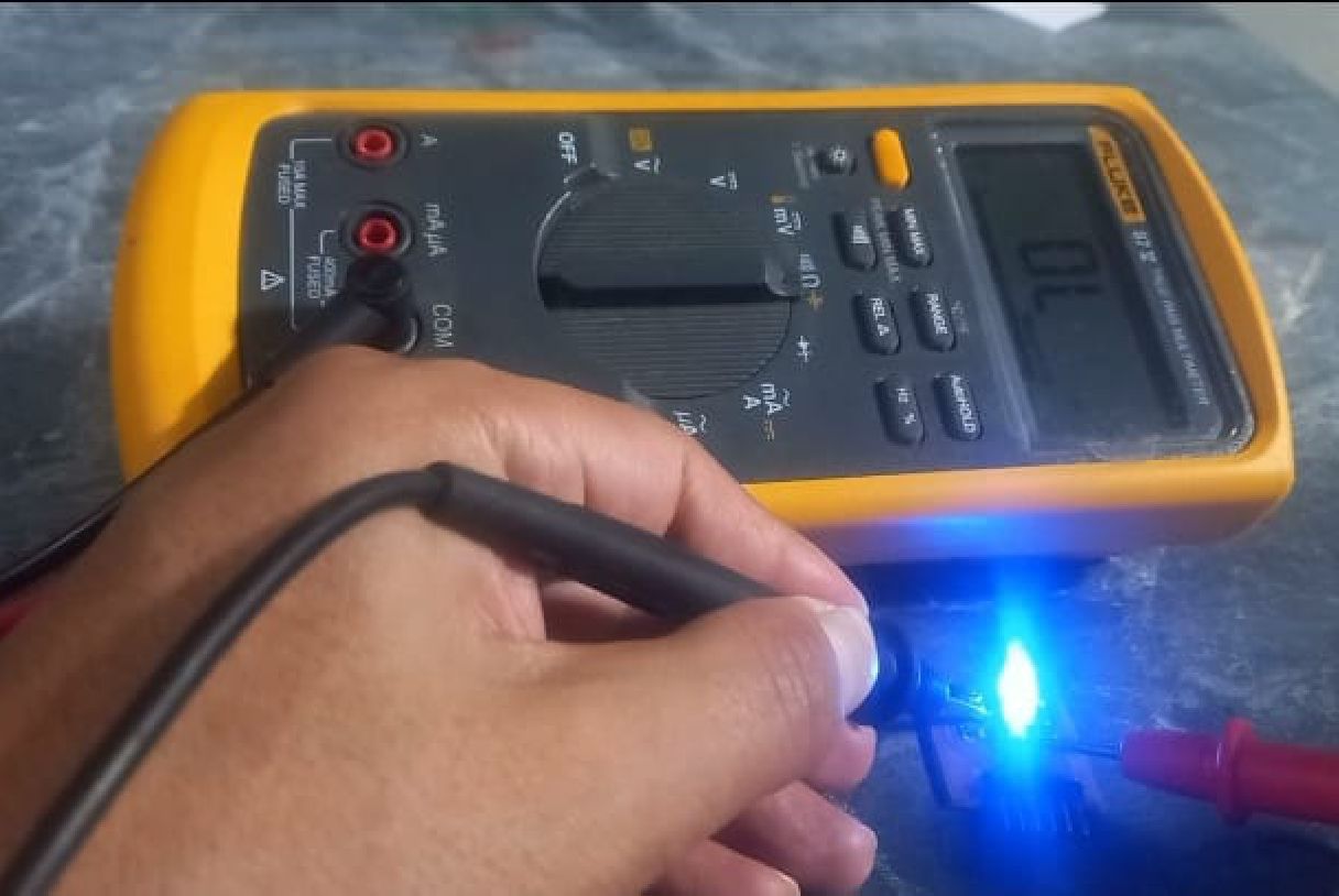
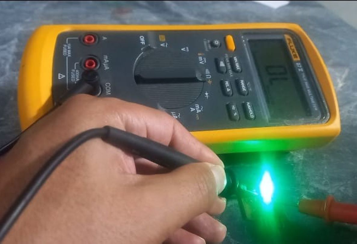
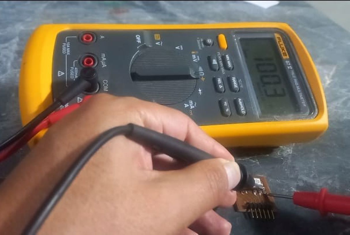
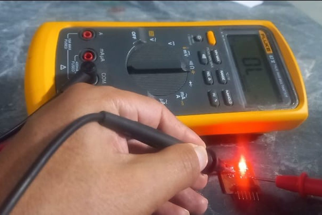
We also carry out a test to verify if the RGB LED is operational. To do this, we perform a diode test. We place the black clamp on the cathode and the red clamp on the anode of the LED, as can be seen in the video.
We learned that it is crucial to perform a calibration using the equipment's own output values or signals of the oscilloscope. Our initial mistake was not understanding why the sensor values were so high and seemed wrong. However, by realizing the importance of testing with the equipment's own output first, we were able to obtain more precise and realistic values. This experience taught us a valuable lesson, and each week we continue to learn and improve.