13. Input Devices
Group assignment
- Probe an input device(s)’s analog and digital signals
- Group Site LINK
Individual assignment
- Measure something: add a sensor to a microcontroller board that you have designed and read it.
Learning outcomes
- Demonstrate workflows used in sensing something with input device(s) and MCU board
Intro
There’s a lot of input devices that can be integrated into electronics! For this week, my goal is pretty simple, use two potentiometers to input two angle values into my final project’s MCU. These two values will determine the latitude and longitude to use for time settings.
Instead of making a new board every week, I wanted to make a dev kit “core module” that’s reusable and can plug in other modules for inputs and outputs. An “arduino board” of my own if you will.
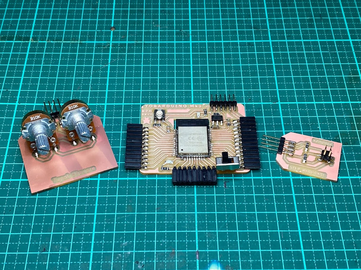
PCB Design and Production
After researching my options and seeing what’s available in the lab, I decided to go straight for the ESP32 as my MCU for my dev kit board, for its IoT capabilities. Ted mentioned there was previously a project called Barduino from Fab Lab Barcelona for exactly this MCU! So I referenced that and also planned to use 2 other input module boards that I design.
One input module will contain 2 potentiometer connections, this will be for my final project.
The other input module will be for a step response input. Neil says these are his favorite input devices, and I can see why- they’re super versatile! So I’d like to experiment with these and try it out as well. Seems like a simple but powerful input device I could add into my final project relatively easily in a later spiral.
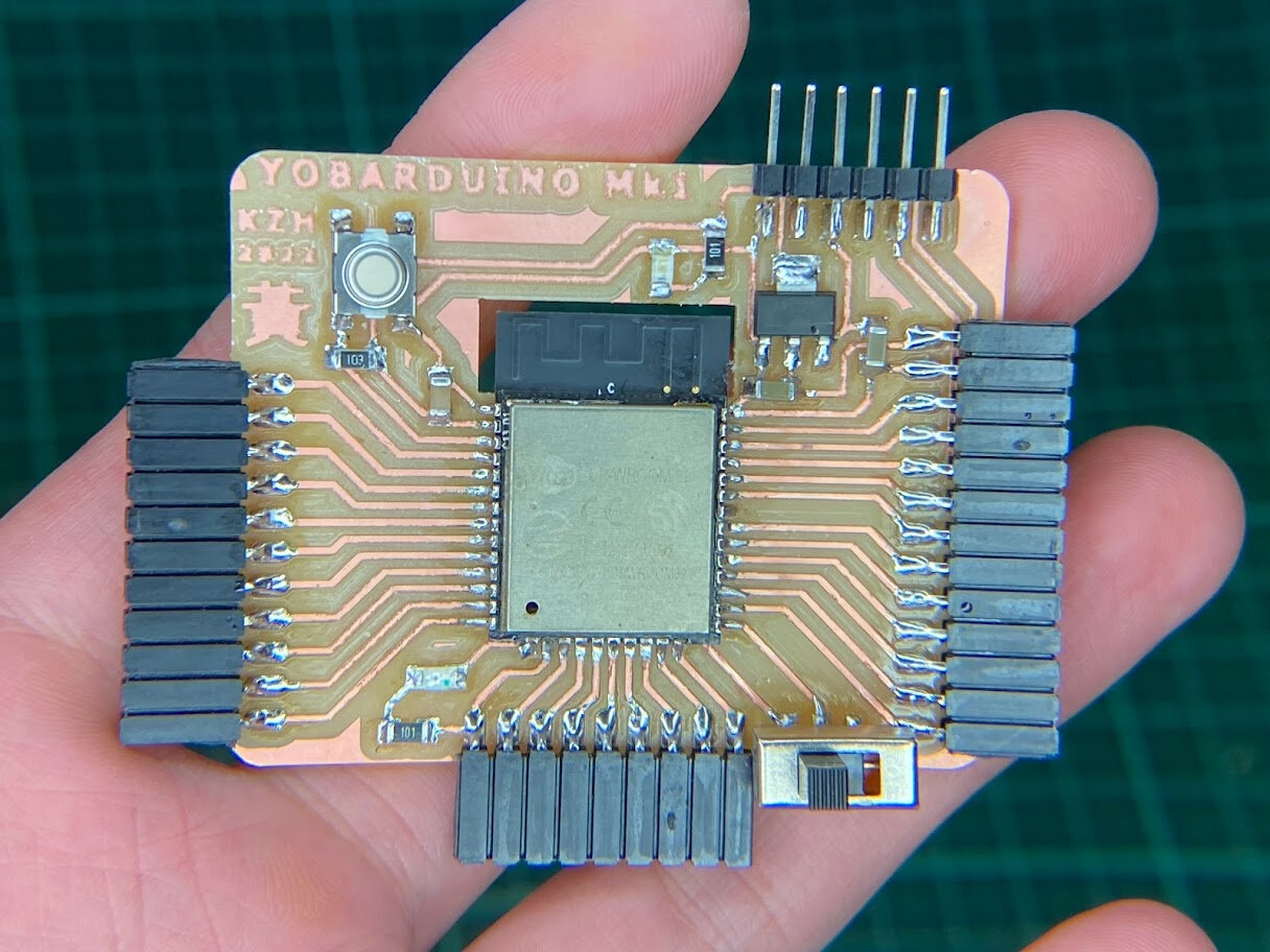
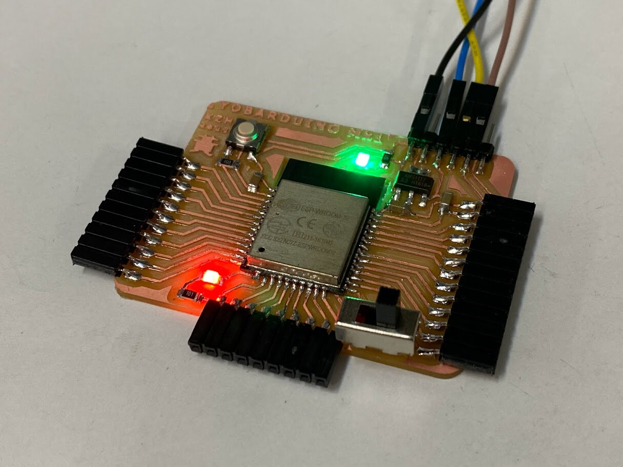
Yobarduino
Referenced the Barduino 2.0 design, but didn’t modify it beyond adding some text to be honest. Wanted to focus on experimenting with input devices this week. Regardless, I named this board Yobarduino to make it more personal since I plan to keep it for a long time to make other projects with as an IoT dev kit.
We don’t have FTDI USB-Serial chips available, so chose to go with the earliest design (v2.0) that just has direct FTDI pins. Having an on-board FTDI converter would be nice, but don’t have the time to wait for that specific chip to come in this week.
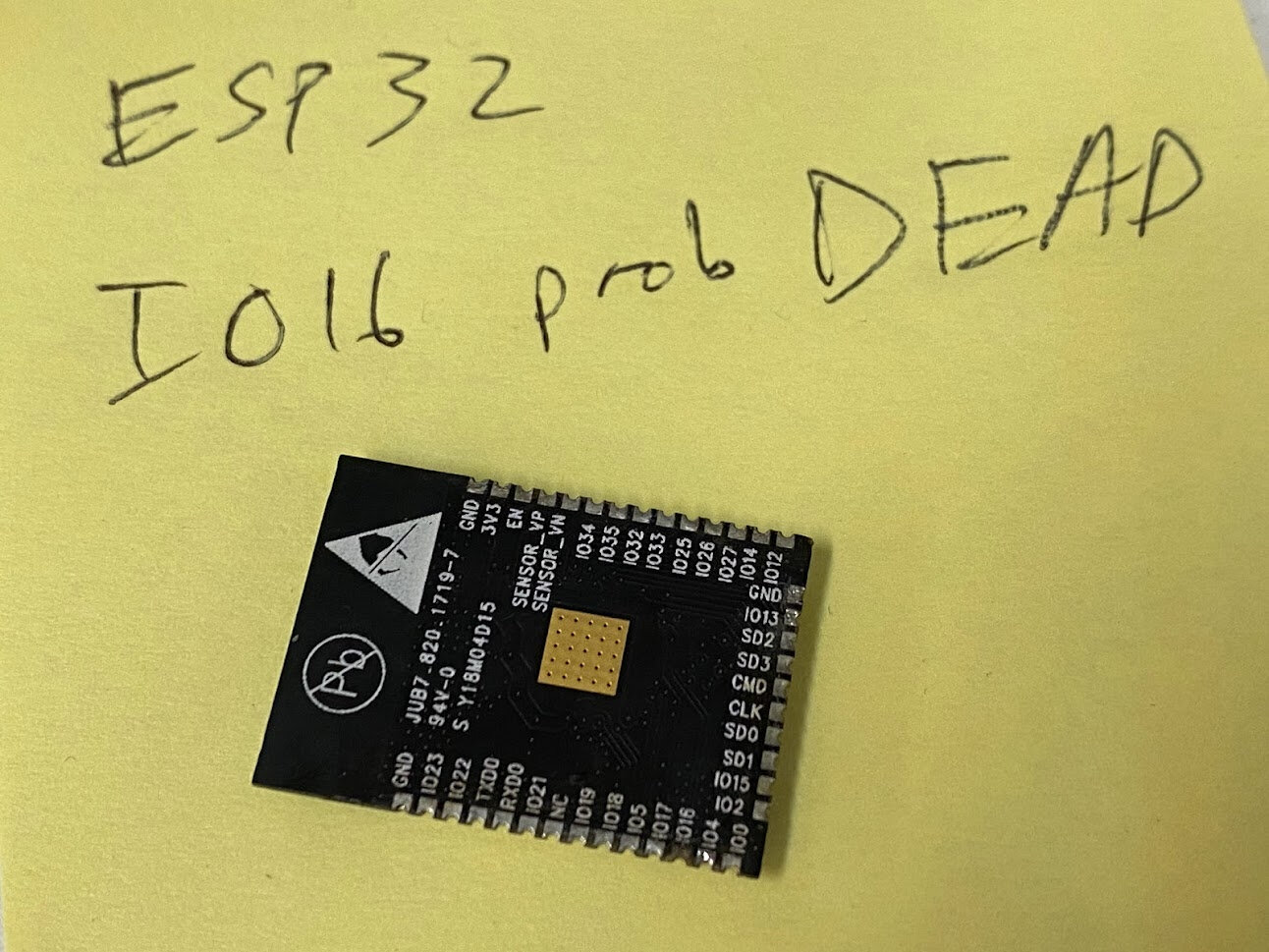
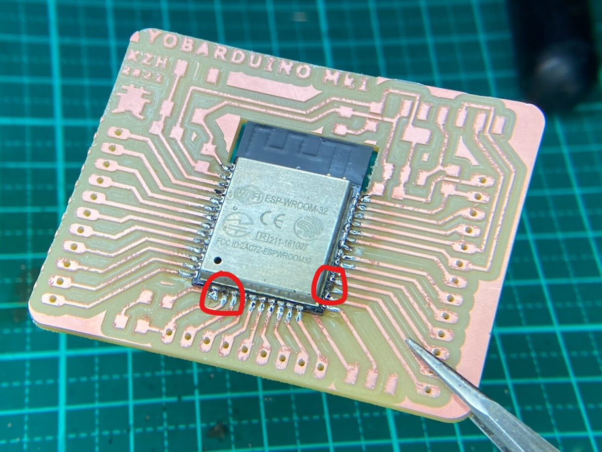
Found the only ESP32 available in our lab on an old unused dev board. Used reflow soldering hot air gun to remove it. Was very nitpicky about removing old remaining solder and was too aggressive with copper wick and heat, and broke pin pad on IO16 and partially on IO13… will test later if they will work after soldering.
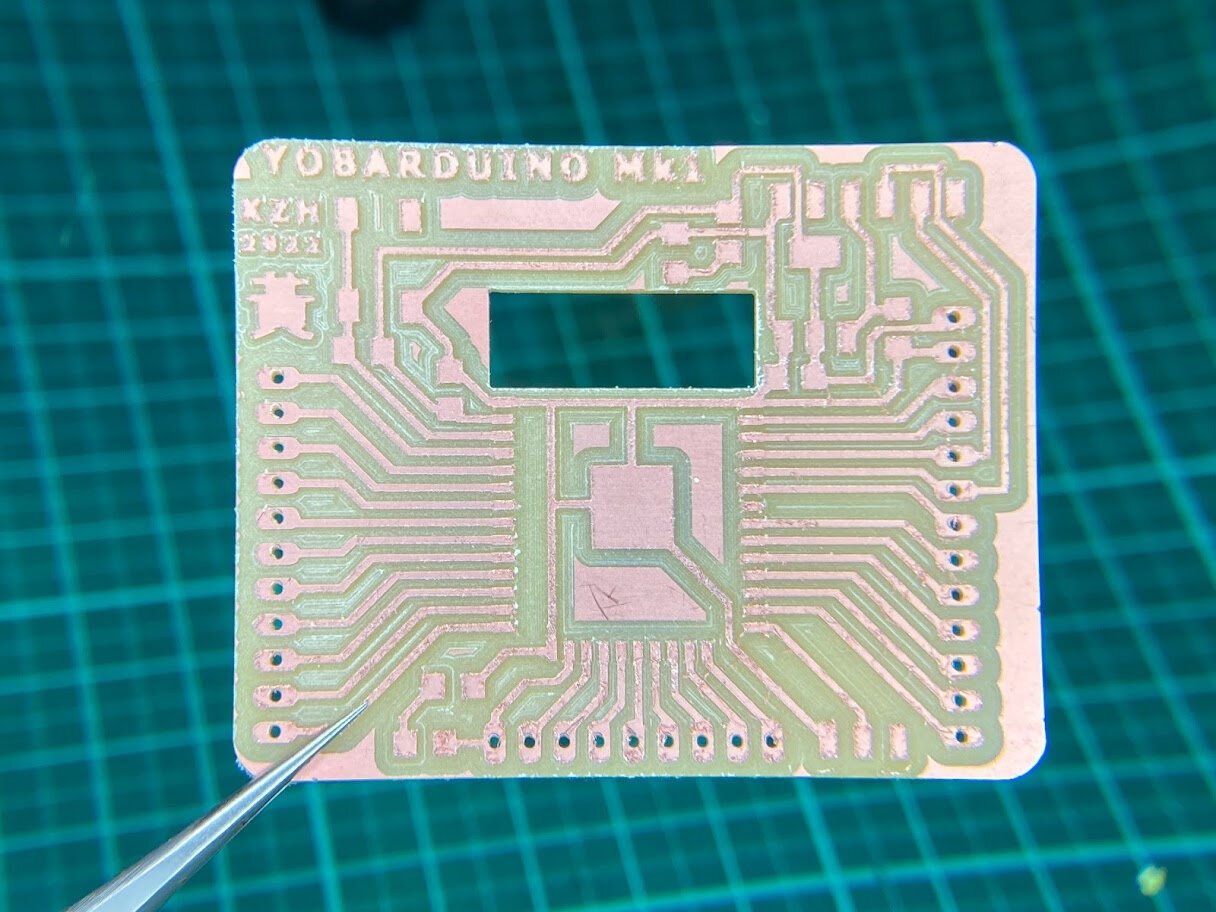
Milled out the board and observed some edges starting to be more burr-y, perhaps my end mill is getting old and dull. Proceeded anyways to cut out holes with thicker end mill. Immediately I noticed something was off! The holes were in the wrong spot completely. Don’t know how that happened but have to redo as some traces were drilled through.
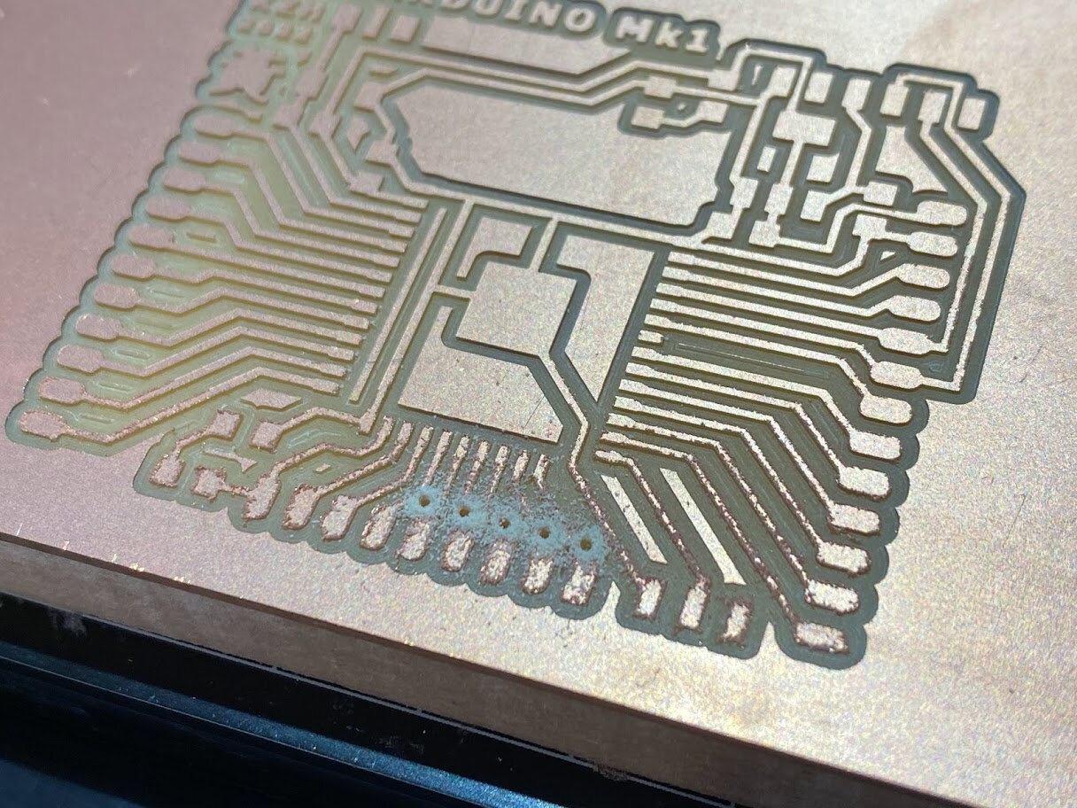
Was more careful this time to double-check my origin point in fab modules and everything lined up the second time. However, the burr-y edges are getting worse.
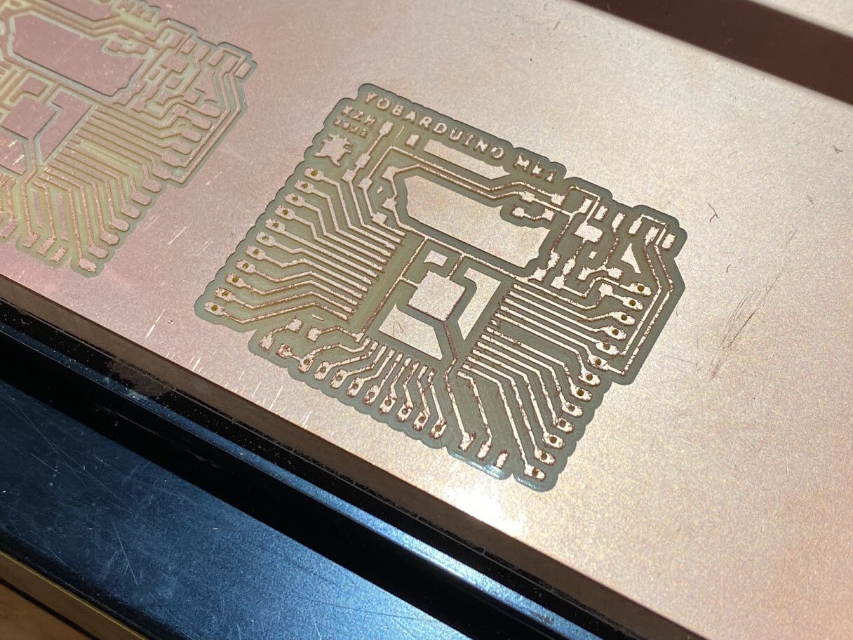
I was concerned perhaps some long burrs might cause shorts between the traces so I carefully used tweezers to ensure burrs were not touching anything and scraped off as much as I could. Nonetheless, the traces looked good enough and I stuffed this board to barduino spec.
Paid extra attention to these 2 damaged pins, adding more heat in hopes solder would seep deeper and make a connection.
For the pin headers I used another blank board to hold it at the right height while I soldered them on.
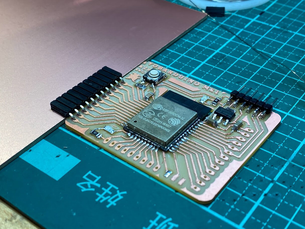
All done!
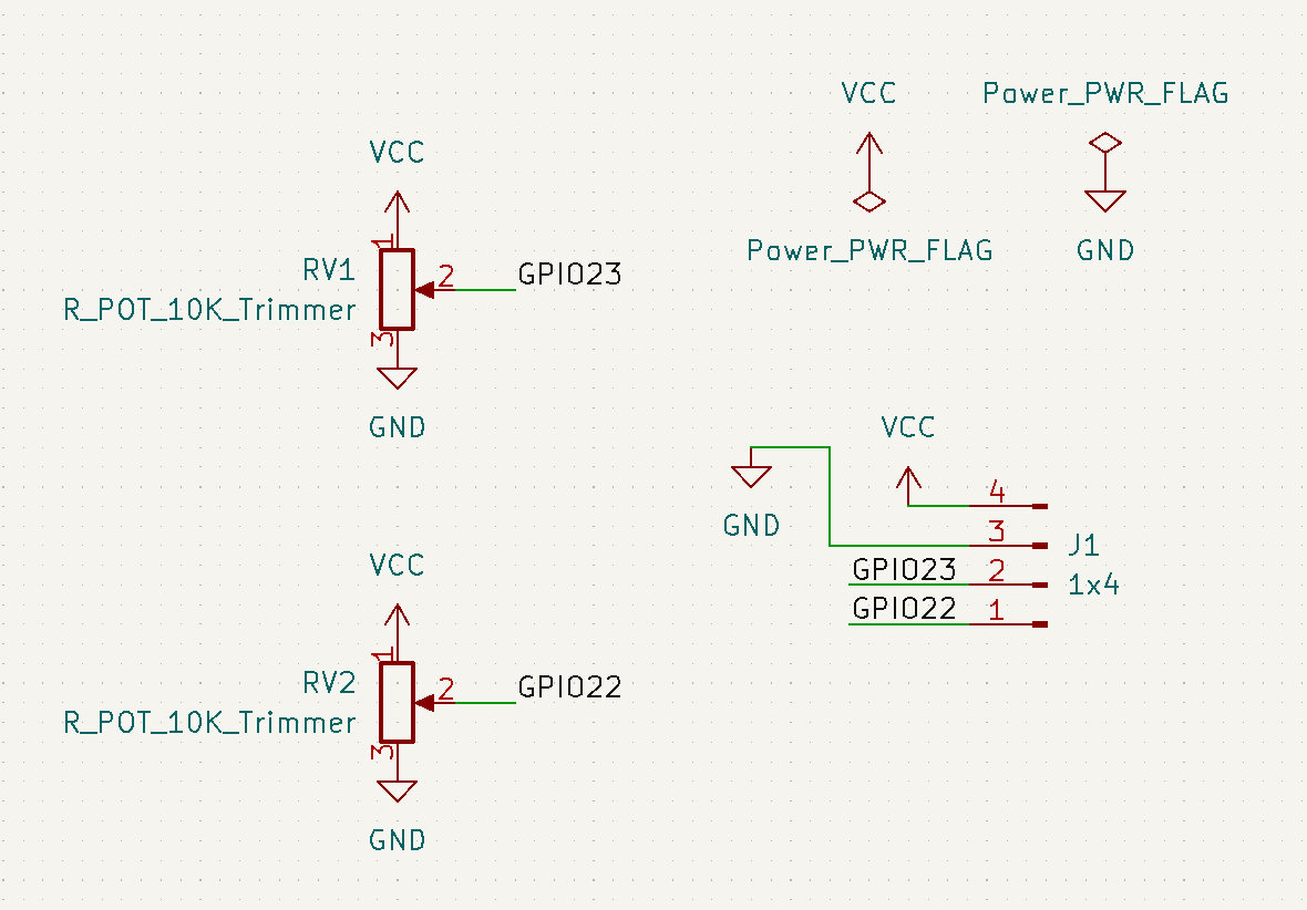
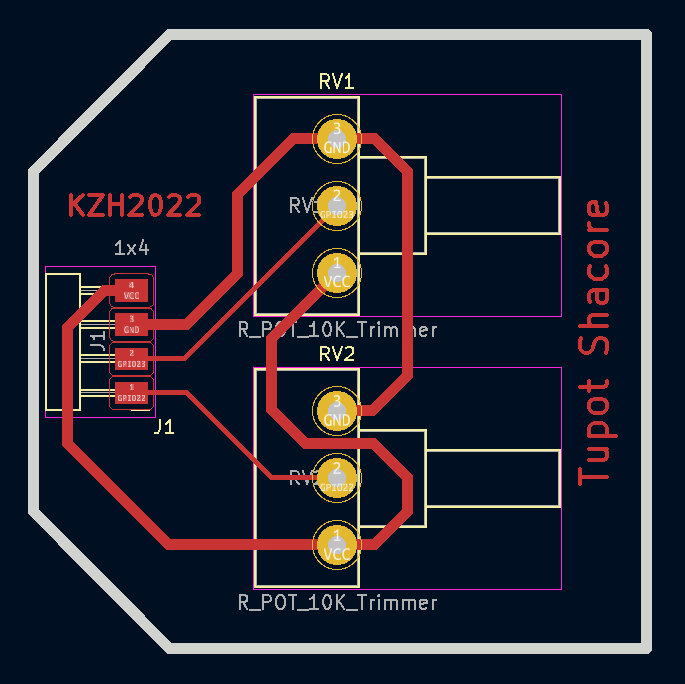
Tupot Shacore
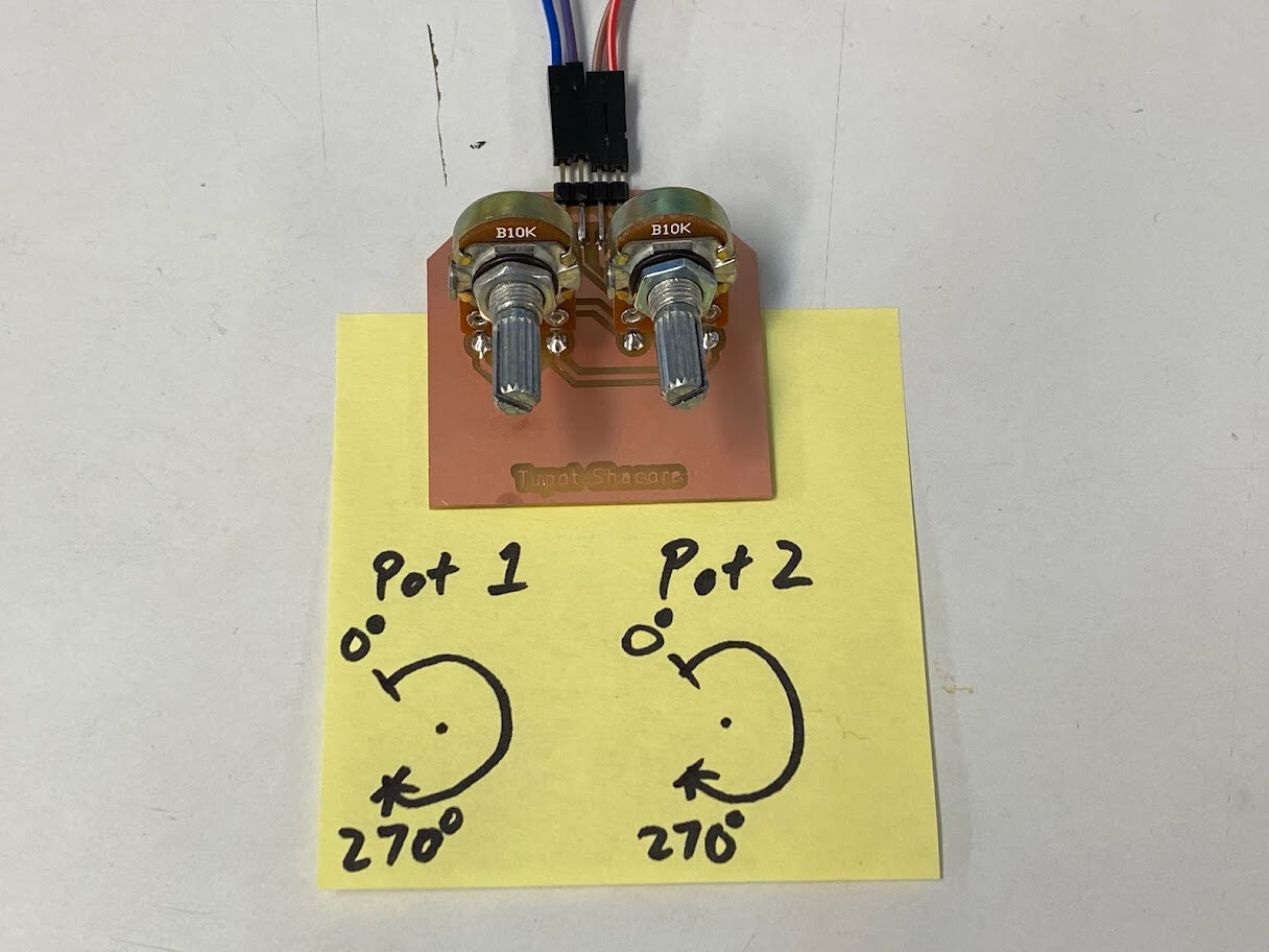
Two pots module as analog input into barduino core. “Pots” being short for potentiometer. Tupot being this module’s rapper name :P
Schematic in KiCad
First PCB layout using default potentiometer footprint in fab library.
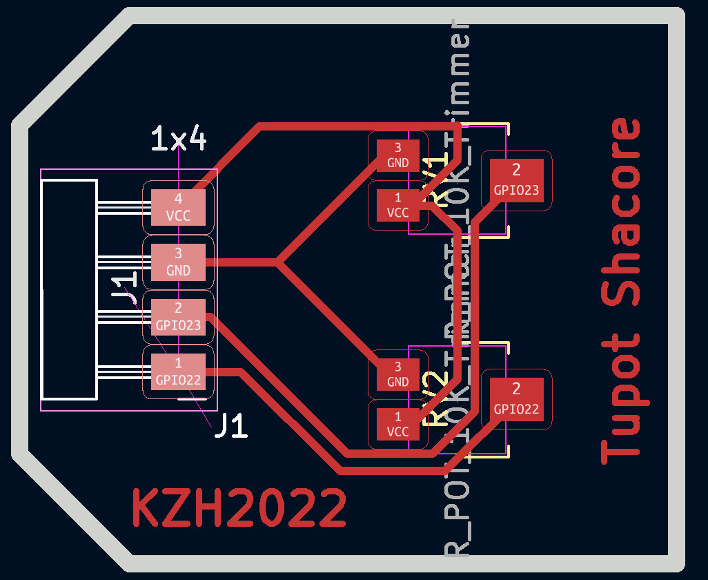
Later found had to use these throughhole potentiometers that were available.
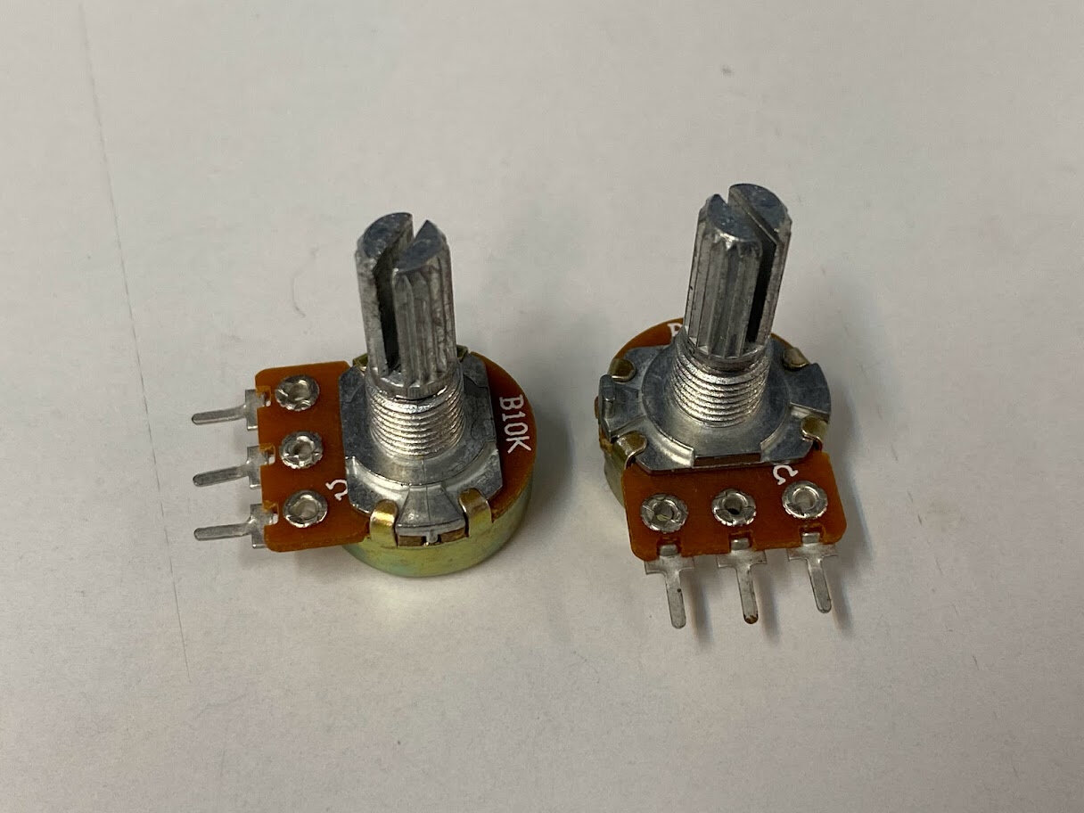
Redid footprints for larger THT potentiometers. Pins 5mm apart.
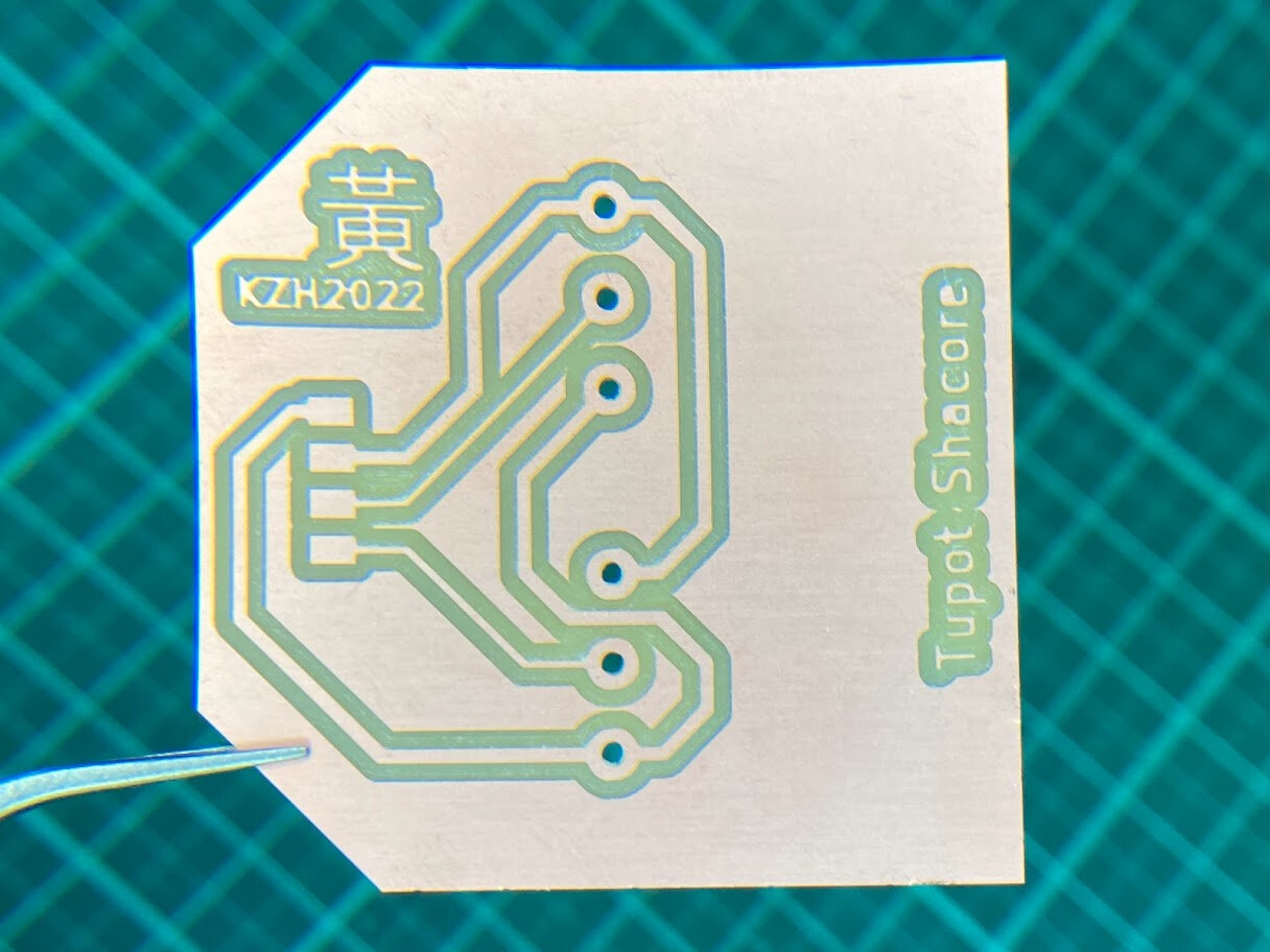
Finished milled board
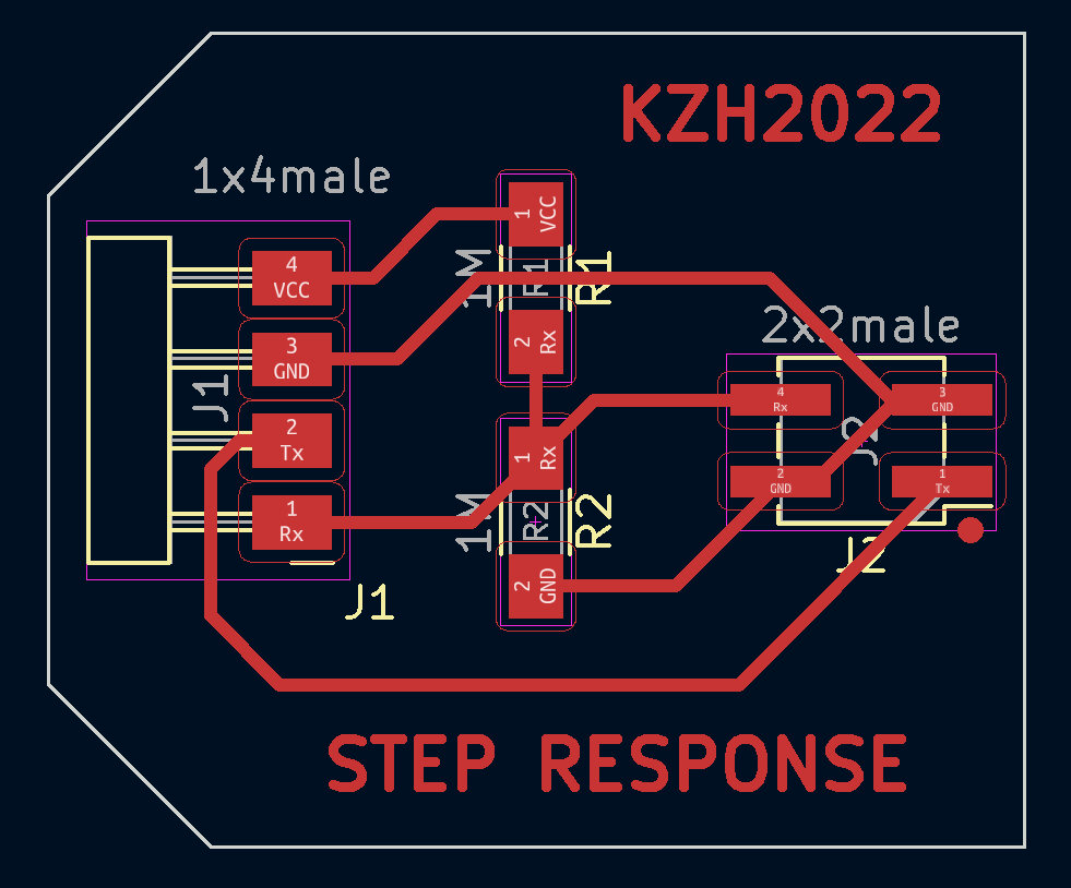
Step Response
Next designed an input module for step response.
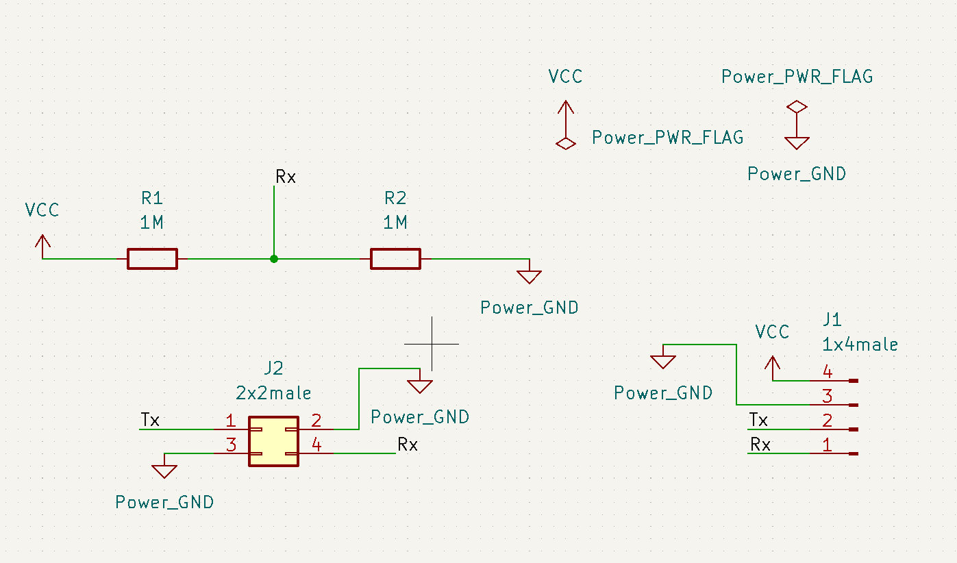
Pretty straightforward layout!
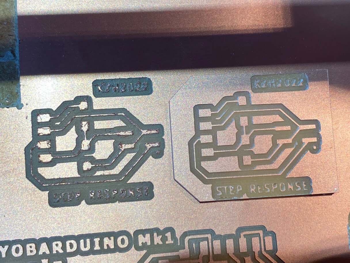
When I milled it, I lowered the feed rate setting from 3mm/s to 2mm/s to see if that would help with the old end mill and burrs. It didn’t really. My end mill is definitely at the end of it’s life. Fortunately, Ted was kind enough to give me another new one, and the difference was night and day!
Old end mill on the left, new on the right.
Finished step response input module board.
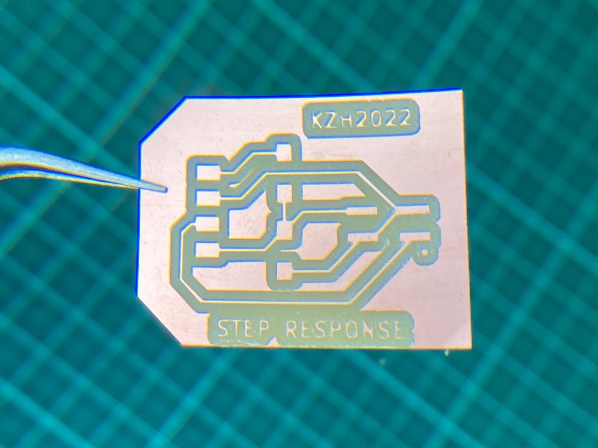
All PCBs done!
Embedded Programming
First need to install ESP32 library into Arduino IDE. In preferences add this link to the “Additional Boards Manager URLS” and install ESP32 in the Board Manager.
https://raw.githubusercontent.com/espressif/arduino-esp32/gh-pages/package_esp32_index.json
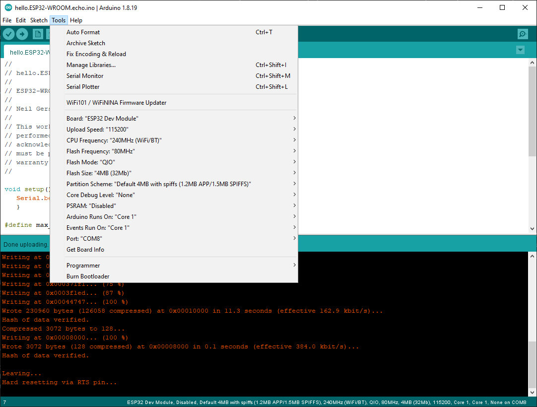
The settings I used to program my ESP32. No programmer is needed. Just use a USB>FTDI converter and connect it directly to the ESP32 barduino board.
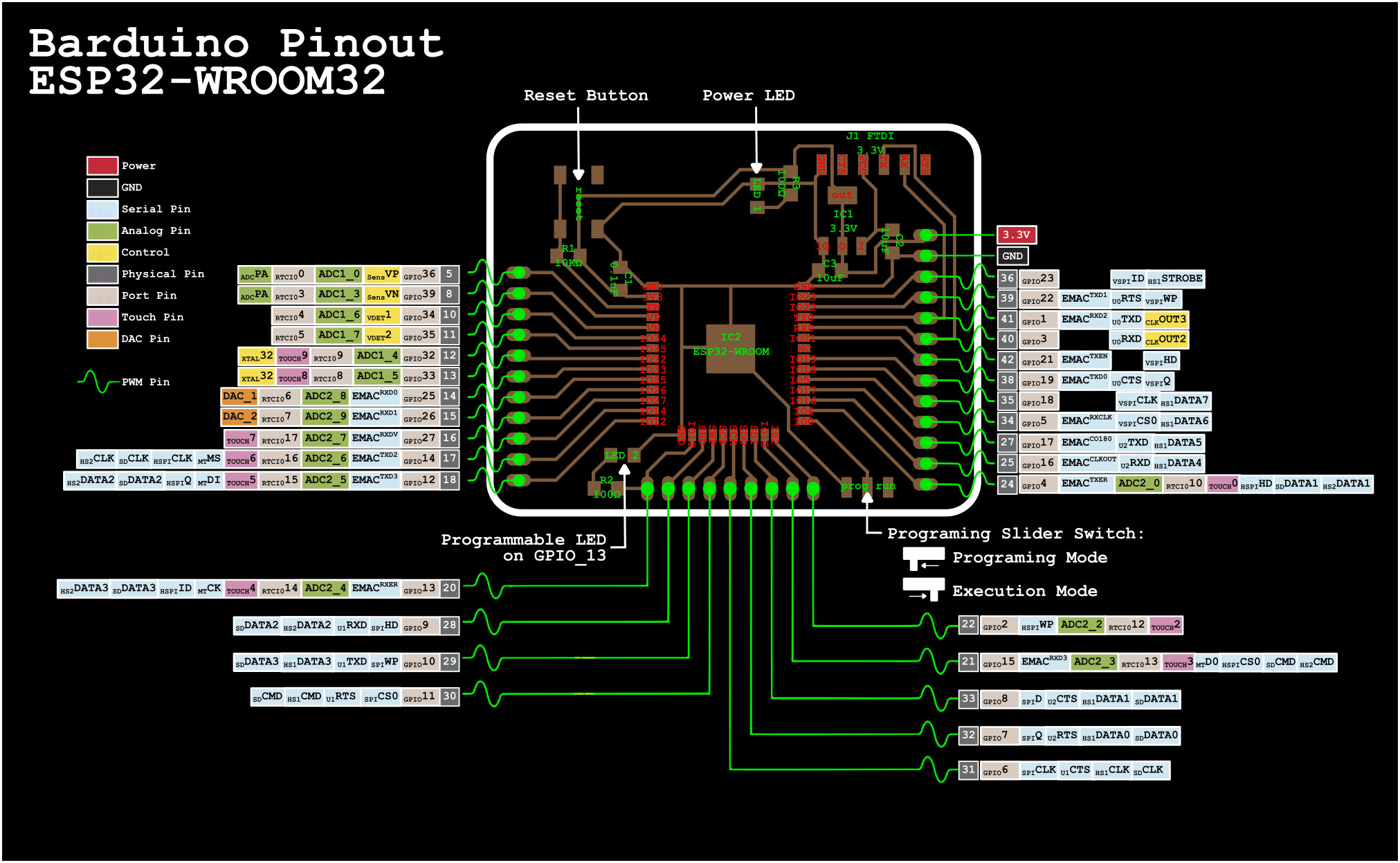
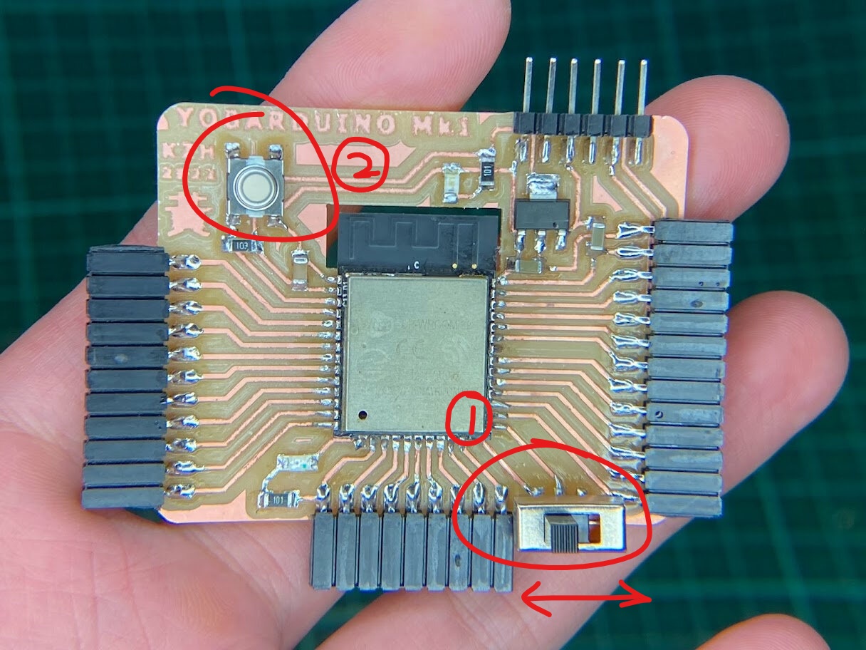
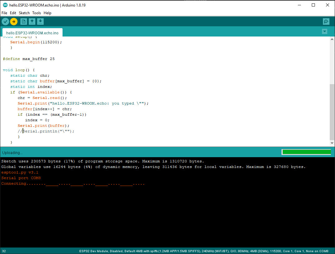
To program the ESP32, the programming switch needs to be switched to programming mode (left). Need to press reset button after switching switch to programming mode. If you don’t do this, when trying to flash new code onto the ESP32, it stops on the “Connecting… ” step, but you can press the reset button then too and then it’ll connect and start flashing code. This step will time out after ~20 seconds though if you’re not paying attention. Best to just keep a habit of hitting the reset button after flipping the switch to programming mode.
Waiting for you to press the reset button…
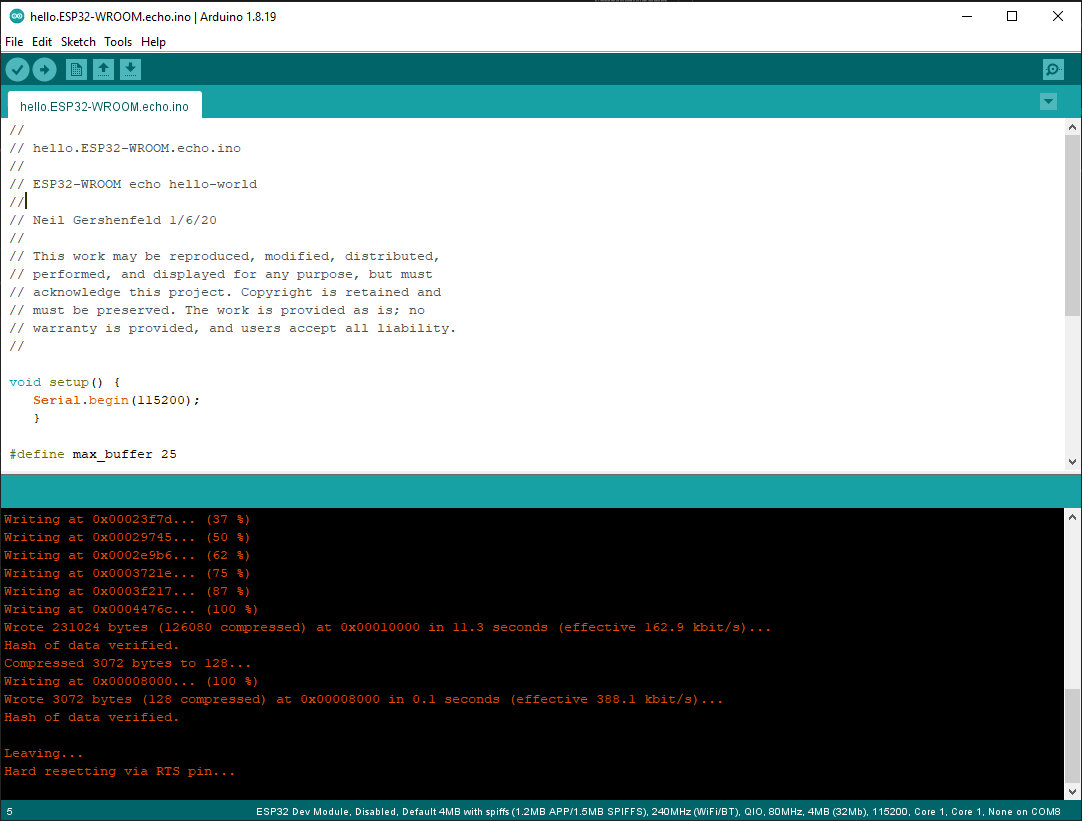
If code flashes correctly, it will show this message. After this, flip the programming switch to the right (execution mode) and hit the reset button again. Now the code is executing.
hello.echo ESP32
First test of the Yobarduino board, flashed Neil’s hello.ESP32-WROOM.echo code for ESP32 from Week 6.
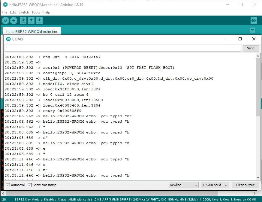
Success! Although the line breaks were a little buggy and I couldn’t resolve it quickly fiddling with Neil’s code, but there’s a response so the ESP32 is alive and working!
blink test code
IO13 which was partially damaged when desoldering from the old dev board has a built-in LED. Flashed blink code to check if the connection is alright. It worked just fine! Solder did successfully seep into the crevice and connect with the remaining pad on the bottom.
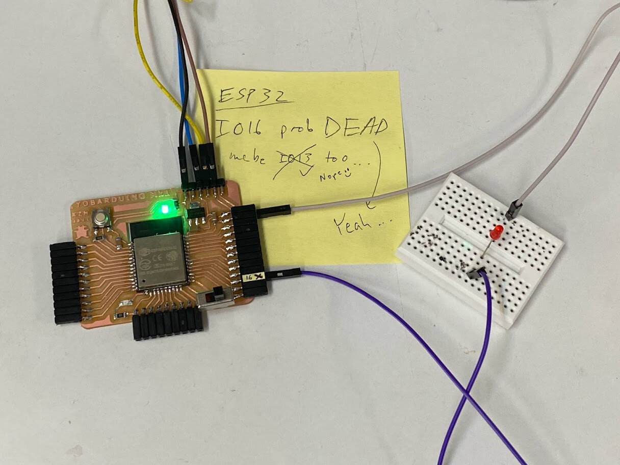
IO16 was not so lucky. Despite plenty of solder, the pad on the module was too damaged and nothing to connect with besides the tiny trace inside the PCB which apparently is not exposed enough. So unfortunately, IO16 is a dead pin for this dev kit.
GPIO16 LED no go flash flash :(
Two pots input
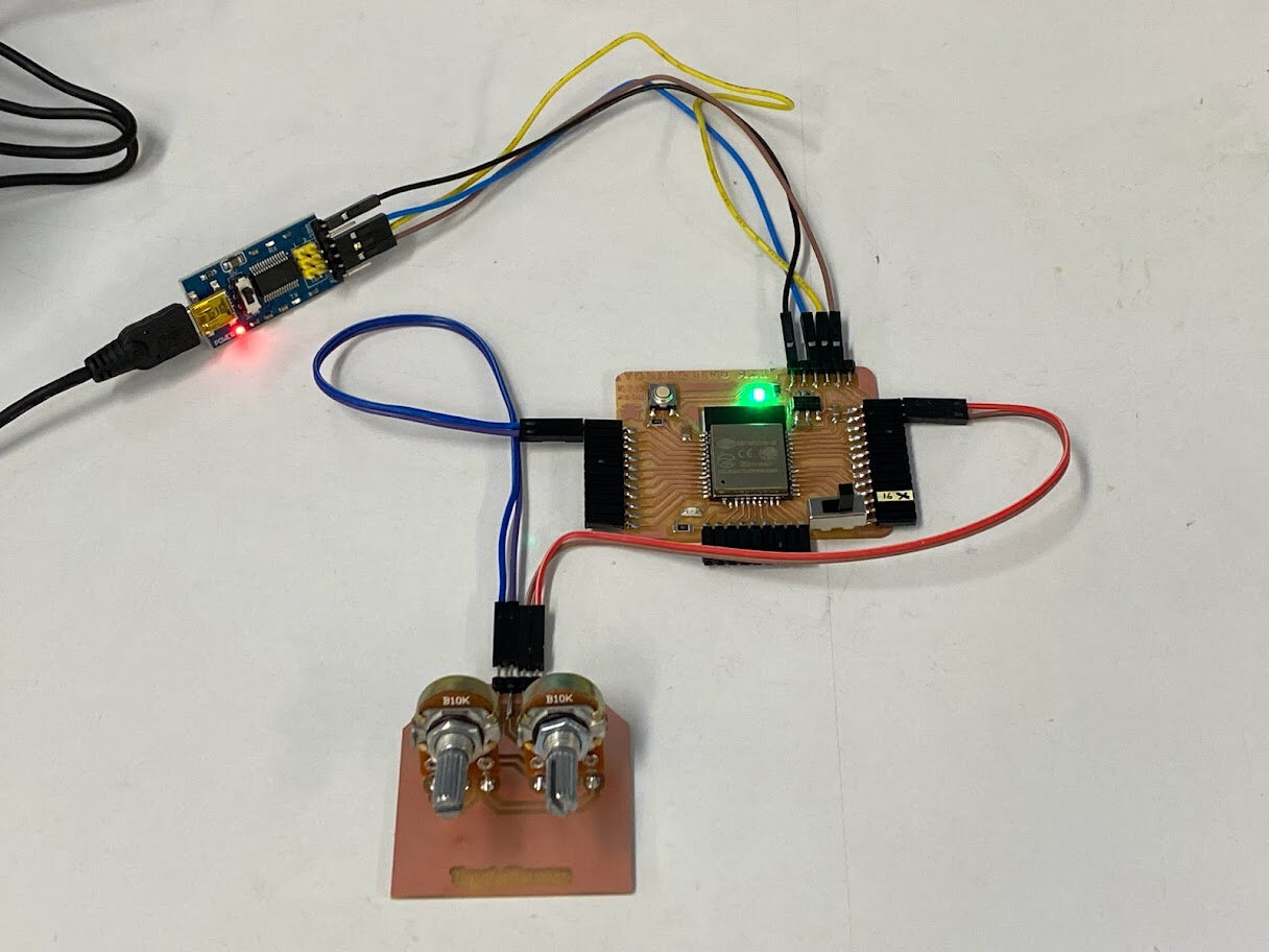
Realized the right side of the ESP32 board doesn’t have analog pins, so the module wouldn’t plug in nicely. Instead, had to use DuPont wires to grab power from the right side and then plug into the left side to access analog pins.
I did try it just to be sure, and GPIO22/23 pins next to power pins definitely does not work to pick up analog input from potentiometer.
The setup.
Angle 0 to 270 on the physical potentiometers.
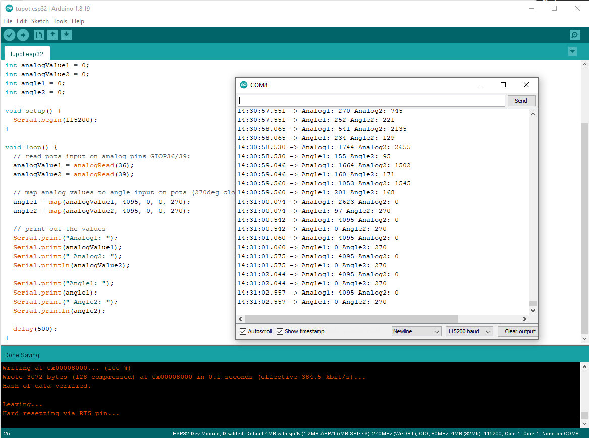
Successful analog readout in the serial monitor!
For final project need one potentiometer that can do 360deg so it can represent all longitudes of the globe. For latitude 180+ is sufficient.
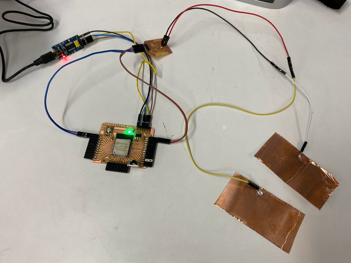
Step response input
Next, tried the step response module. Again, unfortunately no analog pins on the right side of Barduino next to the power pins, so had to connect the module via DuPont wires.
The setup.
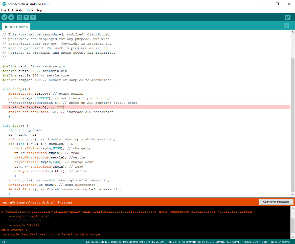
Neil’s txrx t1624 code compiled for ESP32 after removing a couple functions it didn’t like (i.e. digitalWriteFast -> digitalWrite), but it didn’t work well for my hardware setup. Ended up modifying Adrian’s step response code (next section) instead and that worked better. Credit to Adrianino.
Functions are different for t1624 and ESP32.
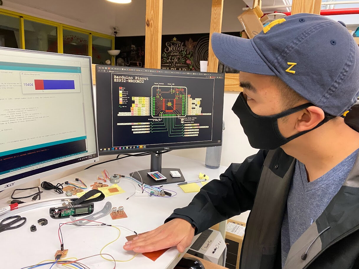
In Adrian’s txrx code I modified Tx and Rx pins to two analog pins of ESP32, and adjusted mapping values to zoom in on a narrower window of readings. Values read were very unstable and sporadic, adjusted N_samples to 500 (from 100) to slow it down and reduce scattering, but the value still jumped around a lot. However, when putting my hand near the two electrodes, and especially putting weight on them, there was a significant response to the serial output, so it was definitely reading something in the electric field.
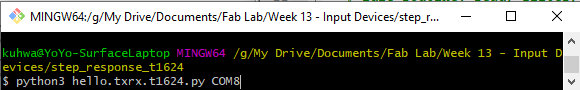
Continued to use Neil’s t1624 pyserial GUI though for reading out the step response input.
Open it like this: Git Bash into the folder where this .py file is saved. Then enter the command as shown below. COM8 is the USB port connected to my Yobarduino board, change to whatever port/device name your board is connected to.
However, when trying to open it, it will throw an error about sys. You have to add this line to Neil’s code to resolve it.
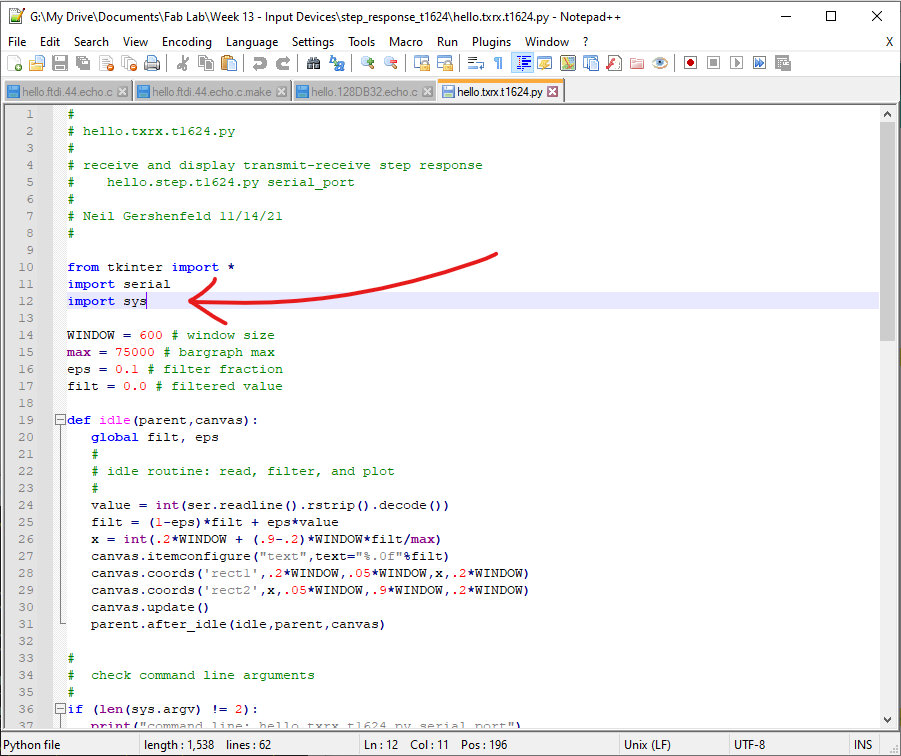
Got a working readout from the step response input but it was unreliable.
Modified Adrianino TX/RX code for ESP32
long result;   //variable for the result of the tx_rx measurement.
int analog_pin = 36; //  GPIO36 of the ESP32
int tx_pin = 39;  //     GPIO39 of the ESP32
void setup() {
pinMode(tx_pin,OUTPUT);      // provides the voltage step
Serial.begin(115200);
}


long tx_rx(){         //Function to execute rx_tx algorithm and return a value
                      //that depends on coupling of two electrodes.
                      //Value returned is a long integer.
  int read_high;
  int read_low;
  int diff;
  long int sum;
  int N_samples = 500;    //Number of samples to take.  Larger number slows it down, but reduces scatter.

  sum = 0;

  for (int i = 0; i < N_samples; i++){
   digitalWrite(tx_pin,HIGH);              //Step the voltage high on conductor 1.
   read_high = analogRead(analog_pin);        //Measure response of conductor 2.
   delayMicroseconds(100);            //Delay to reach steady state.
   digitalWrite(tx_pin,LOW);               //Step the voltage to zero on conductor 1.
   read_low = analogRead(analog_pin);         //Measure response of conductor 2.
   diff = read_high - read_low;       //desired answer is the difference between high and low.
 sum += diff;                       //Sums up N_samples of these measurements.
 }
  return sum;
}                         //End of tx_rx function.


void loop() {

result = tx_rx();
result = map(result, -30, -100, 0, 1024);  //I recommend mapping the values of the two copper plates, it will depend on their size
Serial.println(result);
delay(100);
}
Debugging ESP32 step response
Checked the Tx and Rx signals on the oscilloscope and found that the TX steps were not square at all! And jumping all over the place. No wonder the pyserial readout was so sporadic and jumpy.
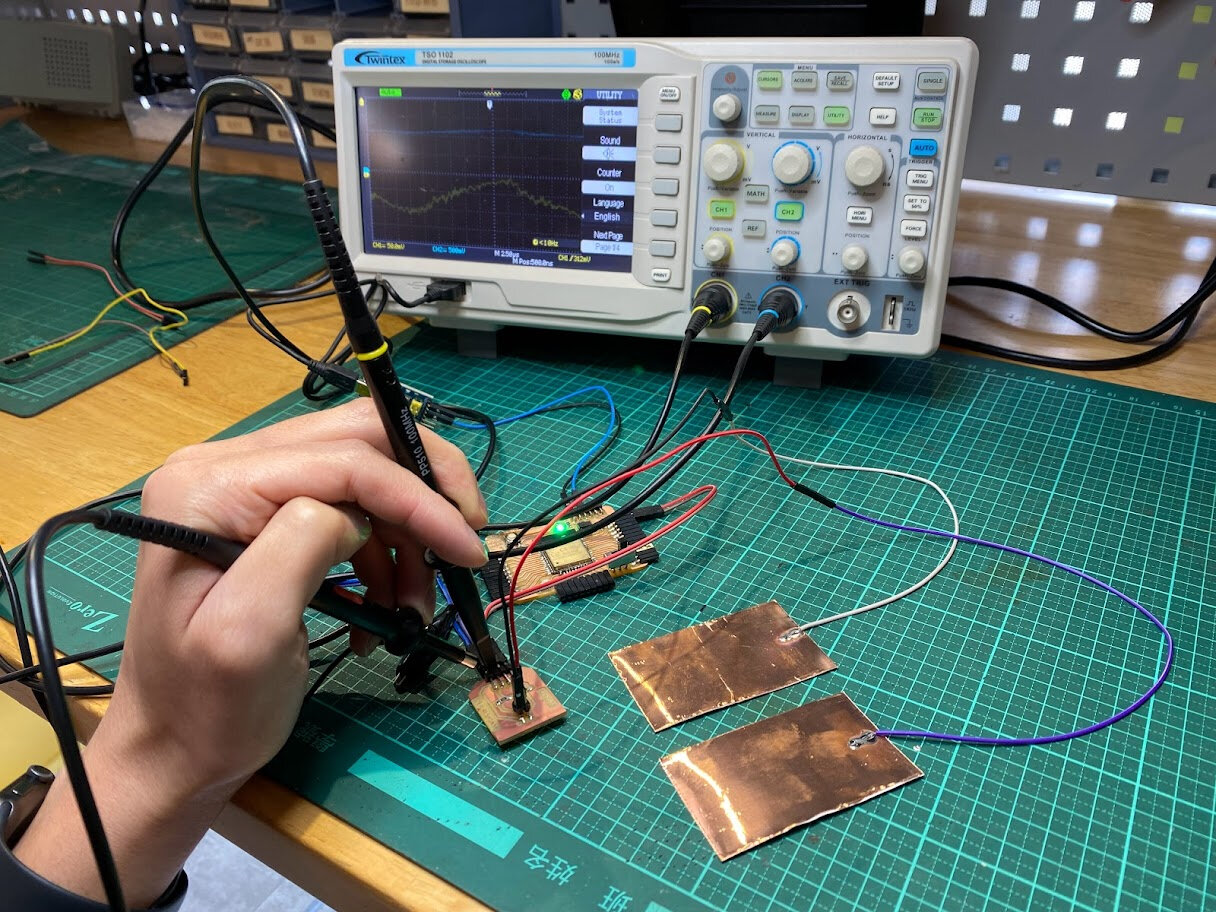
Not sure what’s causing this, as I referred back to the ESP32 pinout diagram and all GPIO pins for sure are capable of PWM signals so creating a simple square function shouldn’t be an issue! Unfortunately no time to debug further this week.
Group Assignment - Probing analog and digital signals
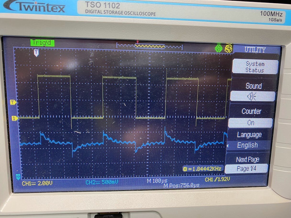
Hanson’s board produced a very clean square wave for step response though! He used Neil’s t45 code with no modification on his t45 dev kit that he made. His pyserial readings are very responsive and accurate.
The yellow line is the Tx steps and the blue line is the Rx response.
See more about our group assignment here.
Conclusion
We rapidly went through the entire landscape of input devices in lecture last week, there are for sure many many to play with and use in different applications. This week I made progress in making a dev board that will save a lot of time in the future, and input modules of potentiometers and step response.
Got the handle on reading inputs from potentiometers (quite easy) and explored how step response works, though it will need more debugging to work with my ESP32 setup.
Future work/Stuff I want to try
- Modify barduino design to have additional module connections with VCC, GND, and analog pins
- Try ALL the other inputs!
- Integrate two pots onto an Earth globe
Useful links
- ESP32 datasheet
- Barduino 2.0
- ESP32 Arduino Core’s documenation
- Adrianino Step Response
- ESP32 potentiometer tutorial