10. Output Devices
Group assignment
- Measure the power consumption of an output device
- Group Site link
Individual assignment
- Add an output device to a microcontroller board you’ve designed and program it to do something
Learning outcomes
- Demonstrate workflows used in controlling an output device(s) with MCU board you have designed
Intro
For this week’s assignment I chose a stepper motor as my output device. I chose this output because my final project will be a clock and I need to very precisely control the angle of a clock hand, so stepper motors were the ideal choice for this application. Servos were ruled out because in position mode (closed loop), they have a maximum angle they can turn, whereas I need my clock hand to continuously rotate while maintaining precise positioning.
This week’s full assignment was delayed due to lack of key IC components in our lab’s inventory, and so we did what we could while waiting for them to arrive.
Spiral 1 trial with Arduino and Stepper Motor Controller
To gain a basic understanding first, I used commercially available boards to control one of the spare stepper motors we had in the lab.
Compoenents:
- 30V/3A benchtop power supply
- Arduino Uno
- A4988 bipolar stepper motor driver (old spare taken off from an upgraded 3D printer)
- JLB stepper motor (Model 17HD4004-13)
- Breadboard and wires
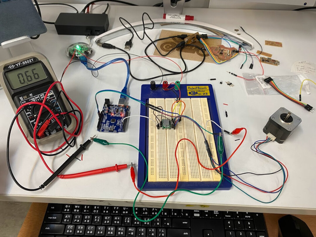
First step was to measure current flow to the stepper motor at low voltage and set the potentiometer on the A4988 so it’s below the max rating of the stepper motor. (1.2A) The max current out of the A4988 was below this so it was fine.
Test code borrowed from DroneBot Workshop made the stepper motor turn clockwise one revolution slowly, wait one second, then turn counterclockwise two revolutions quickly. I could not find a datasheet for the JLB stepper motor model, but turns out the default 200 steps per revolution in the code was spot on!
It successfully worked! But every time the motor was powered on and off, it lost it’s position. The full revolutions were still precise but this is not a good sign for an accurate clock hand. Looked into encoders potentially as a method to solve this problem for my final project.
The speed was really fast, way too fast to be a clock hand. I tried adjusting the PWM delays to be higher, which slowed it down somewhat, but beyond a certain length of delay, the stepper motor started to be fast again. PWM probably doesn’t work this way, and I need to figure out how to program it correctly.
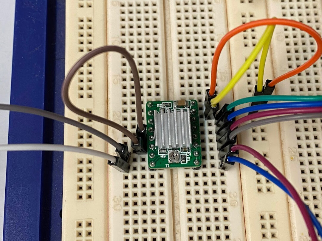
Wiring to A4988. Microstep pins not used yet.
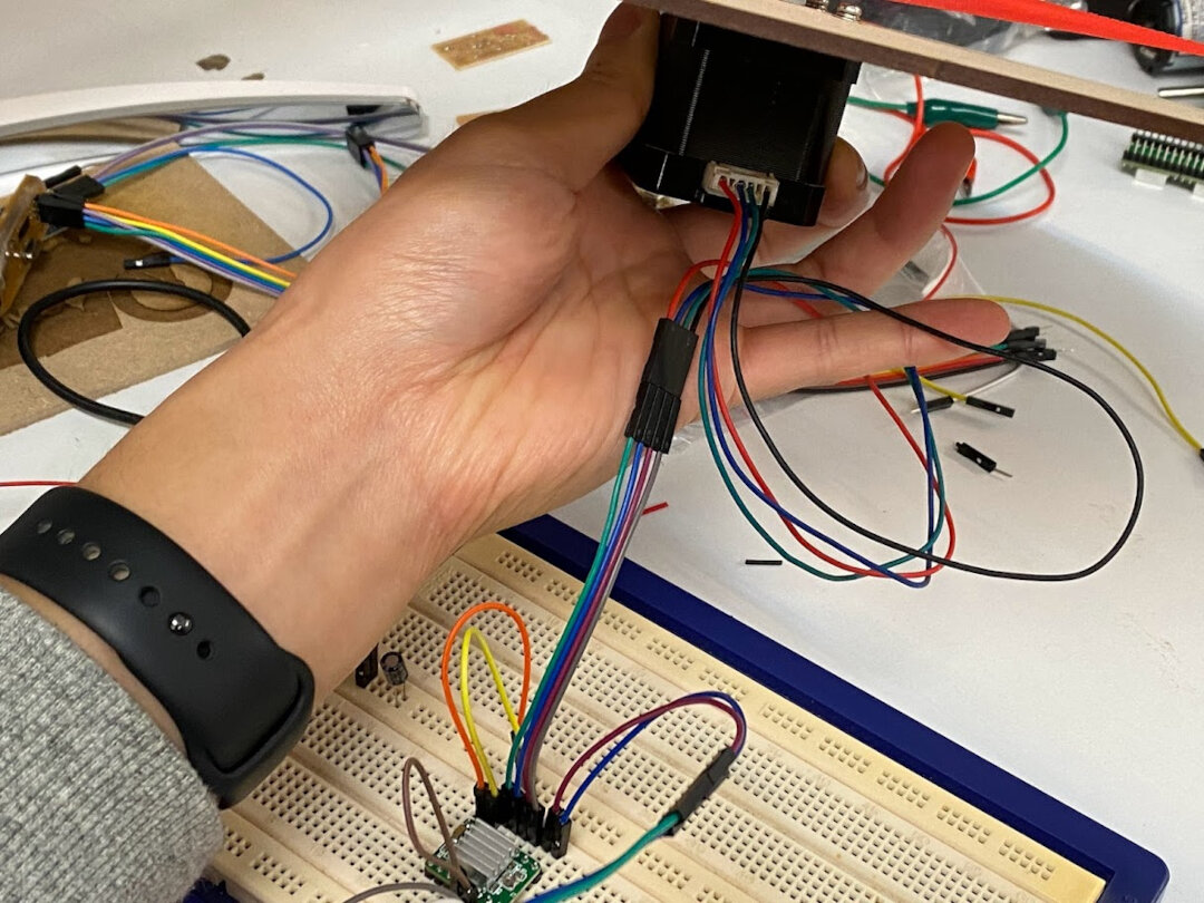
Wiring to stepper motor from A4988.
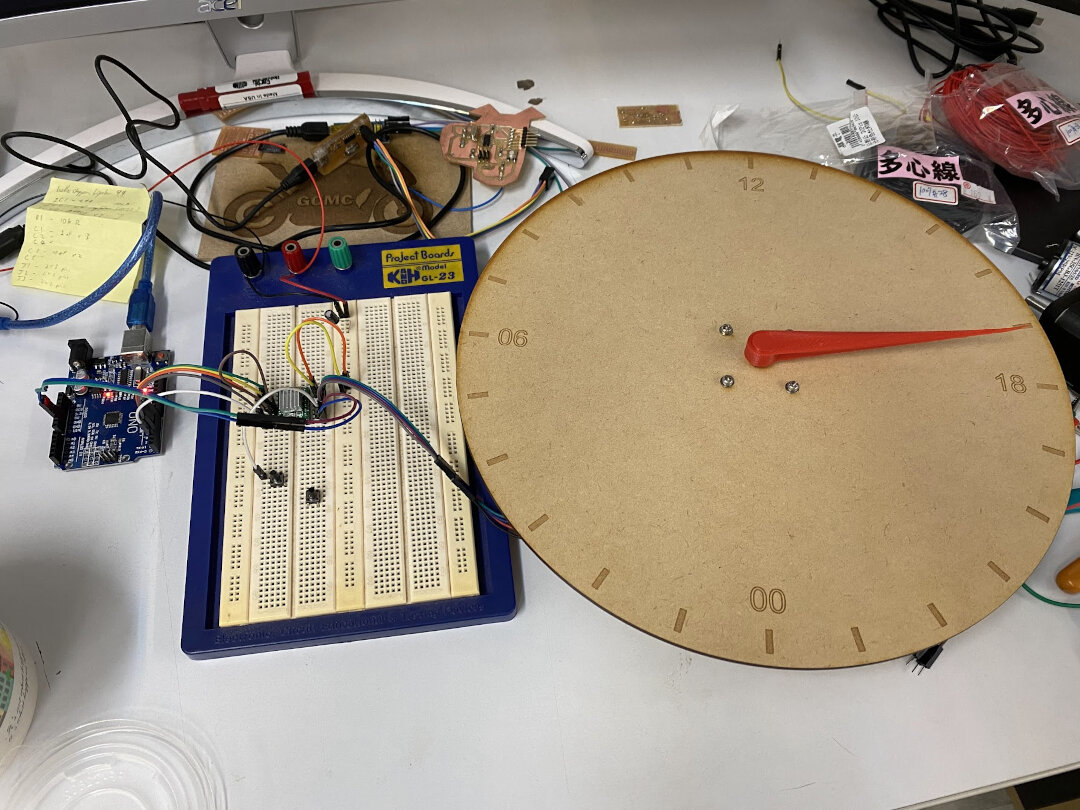
Lasercut a 24 hour clock face and 3D printed a clock hand for Spiral 1 of my final project.
Microstepping
Since I had not modified any of the microstep pins, I tried that next. By adding wires to the Arduino Uno board to pull HIGH the MS1, MS2, MS3 pins on the A4988 driver board, I increased the microstep resolution to 1/16th step. Adjusted my code for “steps in a revolution” variable to be 200 x 16. Now it moved much smoother (smaller steps) and also slower. But it was still too fast.
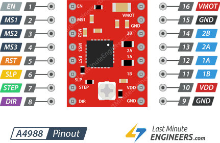
| MS1 | MS2 | MS3 | Microstep Resolution |
|---|---|---|---|
| Low | Low | Low | Full step |
| High | Low | Low | Half step |
| Low | High | Low | Quarter step |
| High | High | Low | Eighth step |
| High | High | High | Sixteenth step |
Also tried limiting current to the stepper motor by turning the potentionmeter on the A4988 down, it helped but the hand started to move in a “clicky” manner. Below a certain threshold, the stepper motor stopped moving completely before reaching a significantly slower speed. So, I don’t think the stepper motor likes this.
For getting even slower, it seems it will need a software solution.
Programming stepper motor control
Target speed of the hour hand is 1 deg per 4 min, or 0.25 deg/min, or 0.0041667 deg/sec.
At 1/16th microsteps, and 200 full steps per revolution, that’s 3200 microsteps per revolution. This means each microstep is 0.1125 deg.
0.1225 deg/step / 0.0041667 deg/sec = 27 seconds per step
So I need to set up my code to count time, and every 27 seconds it moves the stepper motor forward 1 step.
Code snippet
void loop() {
  // Set motor direction CCW, clock face clockwise
  digitalWrite(dirPin,LOW);

  // Step motor forward one step every 27 sec
  digitalWrite(stepPin,HIGH);
  delay(1);
  digitalWrite(stepPin,LOW);
  delay(26999);

  Serial.println("stepped forward!");
}
Henlo44 board controlling A4988 motor driver
I realized later that I didn’t have to wait to make a new custom board to control the A4988. The henlo44 “button blink” board I already made in Week 6 has two spare digital IO pin connections I could use from the FTDI connector, and that was basically all I needed to signal to the A4988.
Human H-bridge
Saw a very well-made YouTube video about how stepper motors work and was inspired to take mine apart and experiment to see how to drive them manually.
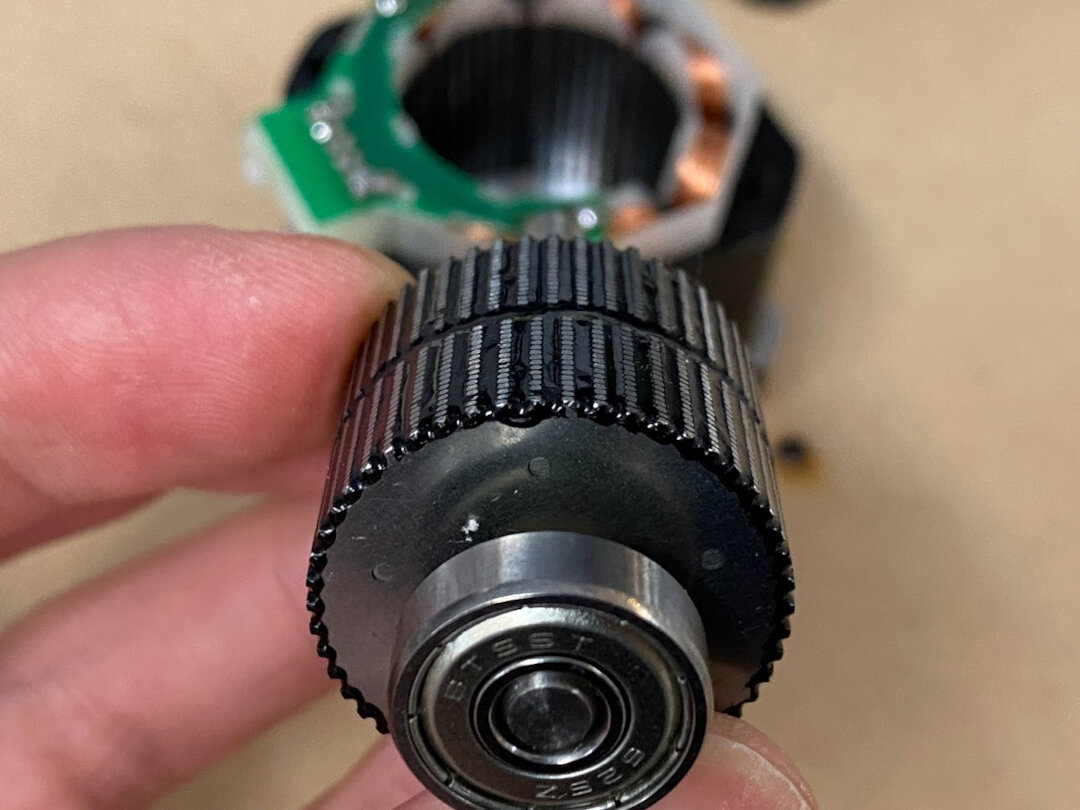
The rotor in the middle is a permanent magnet with 50 teeth. It’s held in an axle with bearings on top and bottom. The coils in the stator are what is activated with current through the 4 wires.
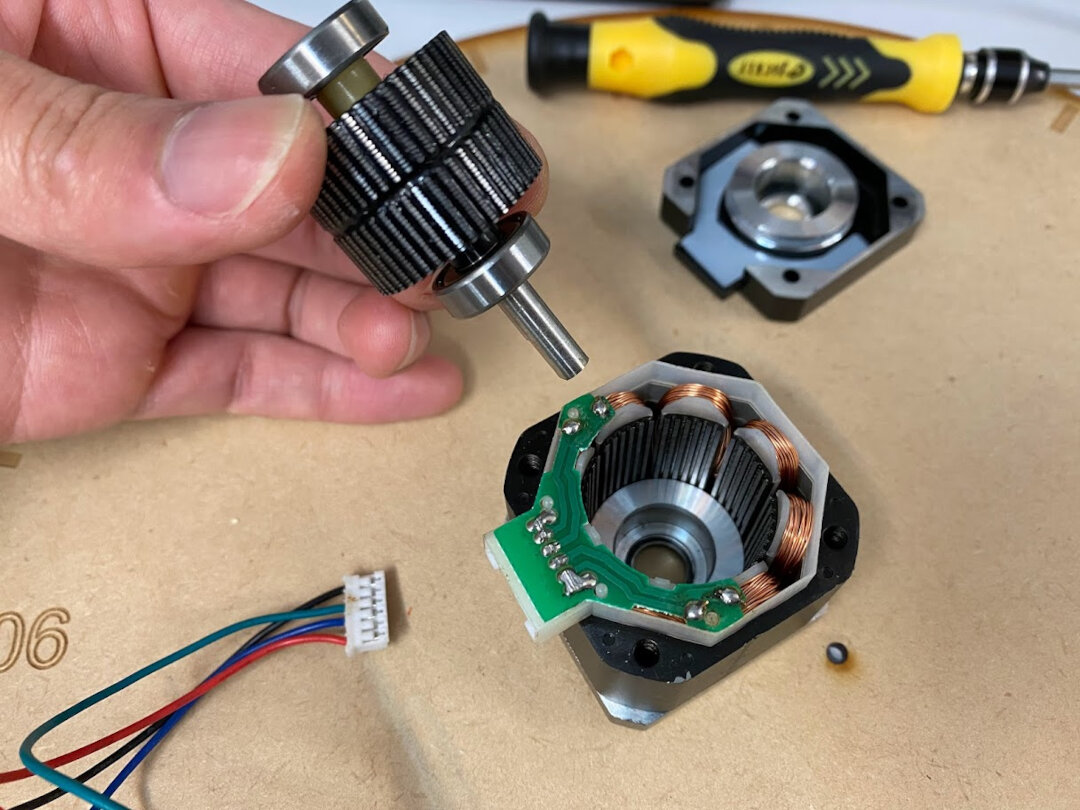
You can see the 2 pole shoes here that are offset by one tooth.
Since we’re still waiting on H-bridge chips to arrive, figured I can be my own human H-bridge first!
Human H-Bridge Driving 2-Phase Bipolar Stepper Motor
Making a board for stepper motor control
Neil had some example hello boards to follow for building a stepper motor control board. One was based on a DRV8428 MCU, the others were based on ATtiny44, which by now I’ve grown more familiar with.
DRV8428 was not available in stock anywhere, which is inconvenient because it has built-in H-bridges for controlling a stepper motor.
The ATtiny44 bipolar stepper motor controller board needs to two H-bridge, A4953, which were also out of stock. However, we could find similar A4950 online, which is currently shipping over.
The unipolar version has an H-bridge but it’s made up of four separate N MOSFET transistors, which we did have!
)
But we are also out of SMD voltage regulators and waiting on them to arrive so in the meantime I tried to jerry rig a 4-pin 5V DC/DC converter to see if it would work. It didn’t.
The DC/DC converter that definitely does not replace a proper voltage regulator.
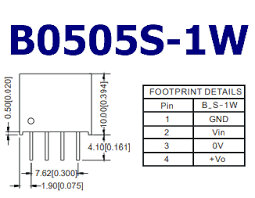
Don’t laugh at my janky soldering of the DC converter. Input 5.5V, within range stated in datasheet. Output was 5.8V!! I had connected pins 1 and 3 because didn’t have separate GNDs on this board. Perhaps it didn’t like that and so not working as it’s supposed to.
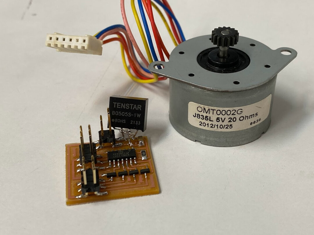
Well the board is made, I will fix it with a proper regulator when it arrives and then should be straightforward to control a unipolar stepper motor with this. I plan to make this into module to plug into my own “arduino” dev kit board I will design soon.
Conclusion
For my final project, I am thinking of using an ESP32 microcontroller since I need WiFi connection.
Things I want to try with more time
- ALL the other outputs XD
- Unipolar stepper motor control with 4 transistors
- Charlieplexing an array of LEDs looks really cool
- RGB LEDs are also really cool, want to include in my final project if I have time
/ NOTES TO SELF Have you answered these questions? Linked to the group assignment page Documented how you determined power consumption of an output device with your group Documented what you learned from interfacing output device(s) to microcontroller and controlling the device(s) Described your design and fabrication process or linked to previous examples. Explained the programming process/es you used. Outlined problems and how you fixed them Included original design files and code Included a ‘hero shot/video’ of your board /
Useful links
- All About Stepper Motors
- DroneBot Workshop - YouTube - Stepper Motors with Arduino
- DroneBot Workshop - Instruction Sheets - Stepper Motors with Arduino
- A4988 stepper motor driver tutorial
- ESP32 Stepper Motor tutorial
- 702 datasheet for MOSFET SMD Type N-Channel
- Fab Lab Inventory Unipolar Stepper Motor
- Fab Lab Inventory Bipolar Stepper Motor