8. Embedded Programming
“Henlo World” in Morse Code
Group assignment
- Compare the performance and development workflows for other architectures
Individual assignment
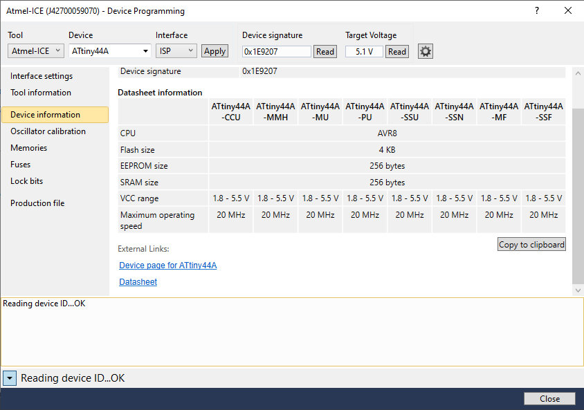
- Read the datasheet for your microcontroller (ATtiny44a)
- Use your programmer to program your board to do something
Learning outcomes
- Identify relevant information in a microcontroller datasheet.
- Implement programming protocols.
Introduction
Embedded programming means putting code onto a microcontroller (MCU) in order to make it do something. In Week 4, we made our own programmer boards, which is needed to interface between our computers (i.e. Windows 10 PC) and a target board. In Week 6, we designed and made our own boards based on one of Neil’s helloworld “echo” designs with the addition of a button and LED. This will be the target board which we will be programming this week.
Goal: make the LED blink when the button is pressed.
Sounds easy enough, but as Neil said, to make this work requires a lot of understanding of how the MCU works. The goal sentence above is an example of “psuedocode,” a human-understandable rough expression of an algorithm, or set of steps (like directions to a place, or a cooking recipe).
So once again in the spirit of spiral development, let’s get a whole basic system working and then get more advanced from there. If a button push can make the LED blink once, we should easily be able to make it blink twice, or make the input come from something else like an ultrasonic sensor, and before we know it we’ll be programming self-balancing robots! (Hopefully…)
Embedded System Structure Design
In the following diagram, in context of this week’s assignmnet, our button is the “sensor” where the input is our finger press, the LED is the “actuator” where the output is light, and all the boxes in between happen within the ATtiny44a MCU. It really is a whole universe in there with a lot going on!
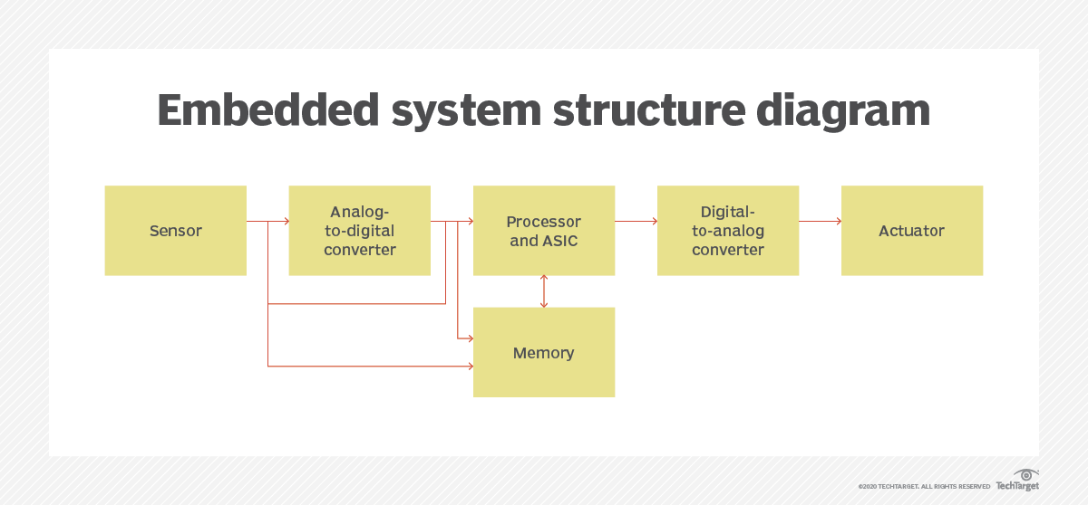 Credit: TechTarget
Current State of Affairs
Week 4 and Week 6 assignments were both left incomplete towards the very end. The boards exist and work to some degree, but the software portion of circuit boards is really hard and the boards weren’t working perfectly as desired by the end of the weeks!
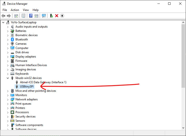
Week 4 FabISP programmer board was able to successfully burn the bootloader firmware onto the MCU according to Arduino IDE console output but upon testing by plugging in directly to my PC via USB, it would not show up correctly as a USBtinySPI (FabISP) in the Device Manager (Windows 10). It remains an “unknown USB device” thus I was hesistant to blow the fuses (permanent) and remove the jumpers to finalize it as a programmer board.
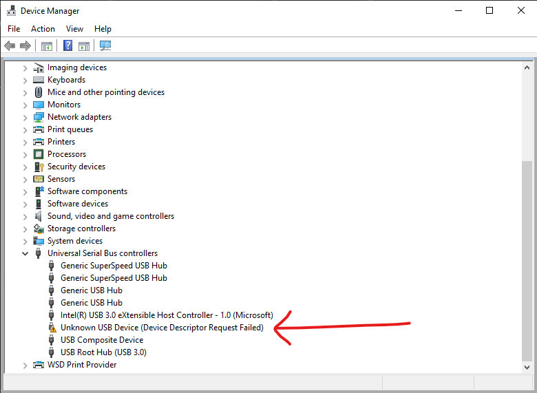
In contrast, my classmate’s FabISP shows up in my Device Manager correctly as USBtinySPI right away when plugged in.
Week 6 custom button-LED board (what I call the “Henlo44 board”) was successfully built and I was able to burn the bootloader via Arduino onto it. I then was able to flash a blink program from Arduino IDE (.ino) onto it and got the LED to successfully blink!
However, when I then tried to flash Neil’s hello.ftdi program onto it with Aruduino IDE it would not work. Tried a different way using USBasp programmer and avrdude via terminal, avrdude stated the program was loaded and the blinking stopped (indicating the previous blink.ino program was overwritten) but then I was unable to get the desired and expected “echo” response when typing to it through the Arduino IDE Serial Monitor. This is as far as I got in Week 6 and have been stuck here on embedded programming.
What I know
Trying to untangle this messy web of knowledge in this new domain, I am restarting my approach to the problem with the given. This is what I know so far:
Bootloaders are the initial software a MCU runs when it first gets powered on. It is actually optional, could skip burning bootloader if want to save memory space. But installing a bootloader allows you to load programs directly from a computer without using a programmer board. A bootloader loads other programs upon boot up essentially.
Programmer boards are boards with fuses blown, so they can’t be re-programmed. This allows them to act as an intermediary to flash programs onto other boards (target boards) including bootloader programs. This is done with In-System Progamming (ISP) pins which are 2x3 header pins. Afterwards, ISP pins actually aren’t needed on a target board. Some makers burn bootloaders onto MCUs separately on a different apparatus before soldering them onto their target boards to avoid a “useless” ISP connection on their target boards later.
Once a target board has a bootloader burned onto it, it can flash programs via USB without a programmer. FTDI and UPDI are communication protocols that can do this, but you need a converter to connect it to a computer via USB like this “Adafruit FTDI Friend”:
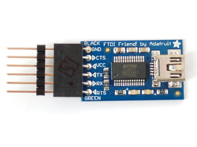
Credit: Adafruit
We are using C as the progamming language for MCUs. C++ is an extension of C that can do object-oriented programming. Arduino IDE uses C++ but with more Arduino libraries.
“Arduino” actually refers to 6 things:
- family of commercial dev boards
- toolchain
- libraries (useful but not very efficient)
- IDE
- bootloader (optional)
- header (for peripherals)
Each of these 6 things has other tools you can use individually instead of Arduino (i.e. using VS Code as your IDE), but it’s just nice that Arduino can do it all, though may have some limitations for advanced users.
Programs needs to be compiled into machine code (1s and 0s) before flashing onto an MCU. This is done by a compiler, in the case of Windows and AVR family of MCUs, it’s avr-gcc and the machine code is put in a .hex file. This is the file that is actually loaded onto the MCU. Chips prefer to read 1s and 0s, so you have to “translate” for them.
Every MCU has an instruction set architecture (ISA). This is how the compiler knows how to turn higher-level code like C into machine code.
Flashing an .ino program onto the MCU with Arduino IDE assumes you have Arduino library included, which takes up space. Using a .c file and Makefile is simpler and more efficient (takes up less space), but you need to use a compiler like avr-gcc to turn the .c file and Makefile into a .hex file before flashing that onto the MCU. This latter method is done in command line i.e. avrdude in terminal.
An .ino program/sketch is just C code though, so you can copy and paste a .c file’s code text directly into an Arduino IDE sketch and upload/flash that onto a MCU with Arduino IDE (after it compiles it for you of course). This is how I got Neil’s hello.ftdi.echo code onto my Henlo44, since he only provided the .c and Makefile for the t44 version. In theory, I could’ve used avrdude in terminal to do the same but didn’t have time to try that this week. Arduino IDE is just simpler and I still prefer GUIs more.
ATtiny44a Datasheet Info
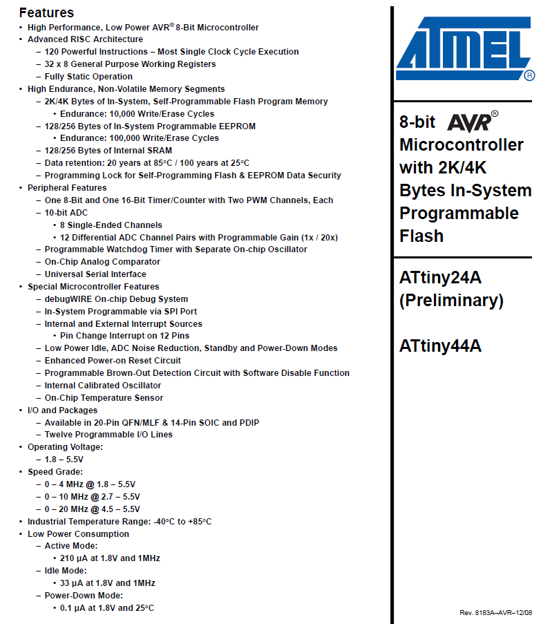
Let’s also review what info we can gather about the MCU we are working with (ATtiny44a) from the manufacturer’s datasheet. It’s 229 pages long! Part of our homework was to read it, or at least skim it. It’s a lot of info and jargon, I Googled what I could with the time we had this week and watched videos about it. Below I pulled out some of the more important diagrams to note from the datasheet.
Here’s the basic specs and features.
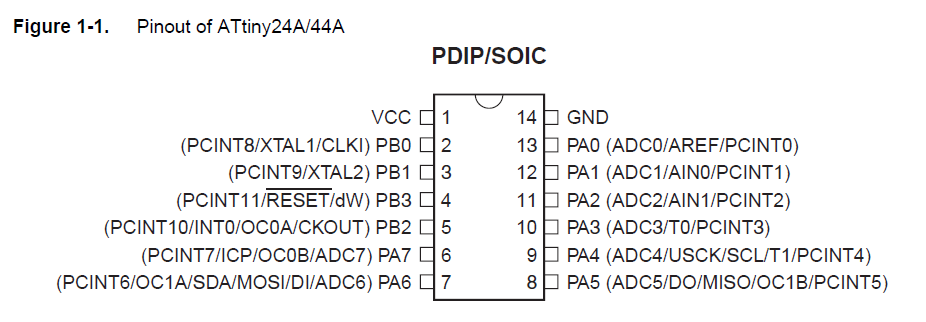
Here’s the very important and useful pin out diagram of the ATtiny44a. This tells us how to connect the pins to it on a circuit board.
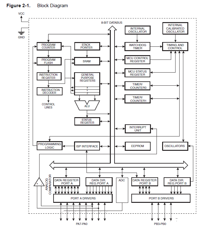
Inside a MCU is a tiny universe of computing. It’s amazing what these millions of tiny transistors can do inside a tiny package. This Block Diagram maps out the different parts inside the MCU.
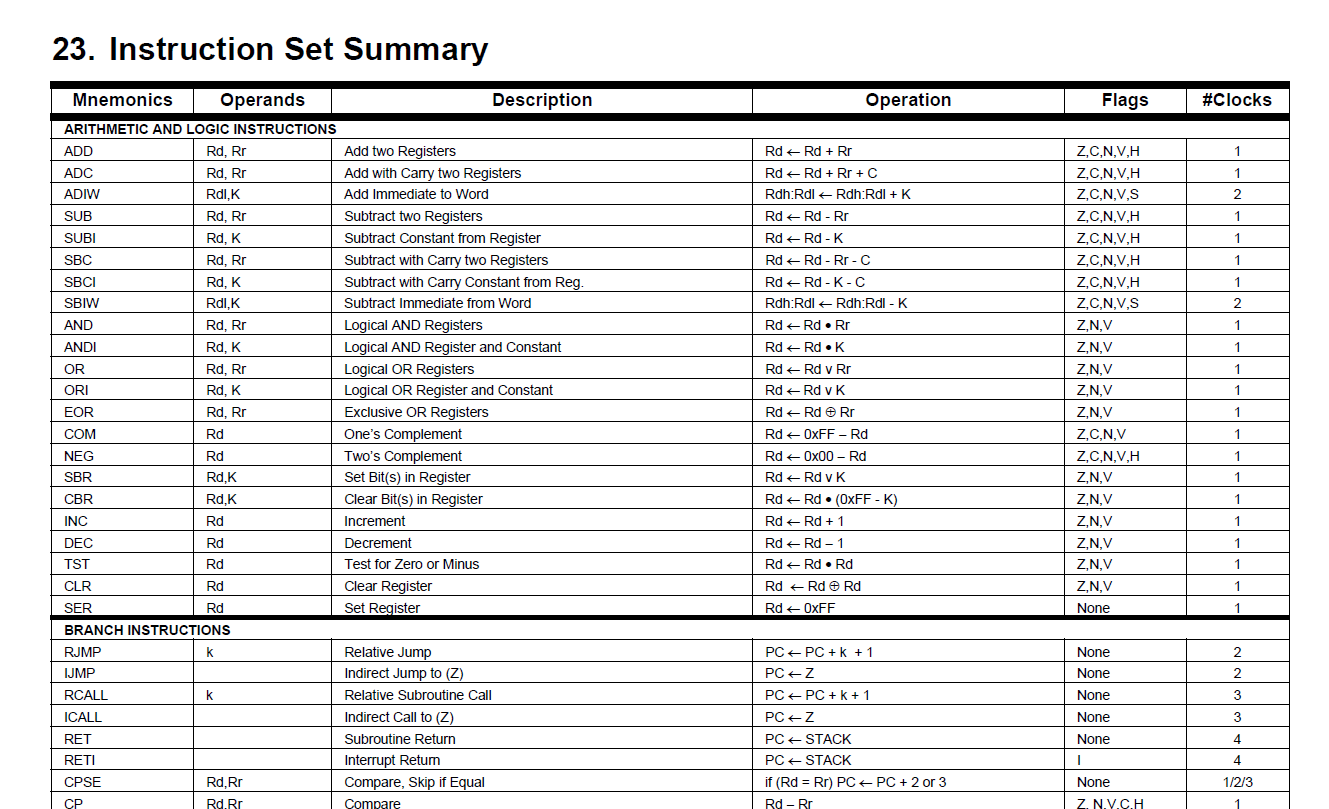
The previously mentioned ISA (instruction set) is partly shown below. These instructions are how we get to machine code with our higher level code i.e. C++.
Troubleshooting
Okay so now that I’ve gathered what I know, continue troubleshooting issues from Week 4 and Week 6, so that I can do the full assignment this week.
Connections and steps are confusing. Avrdude commands aren’t working the way I hoped and keep spitting out errors. So first let’s debug the hardware and make sure that’s not the issue.
Installed Microchip Studio (formerly known as Atmel Studio) to use as the most powerful and also OEM debugging tool. First problem came up: “Low Target Voltage” warning.
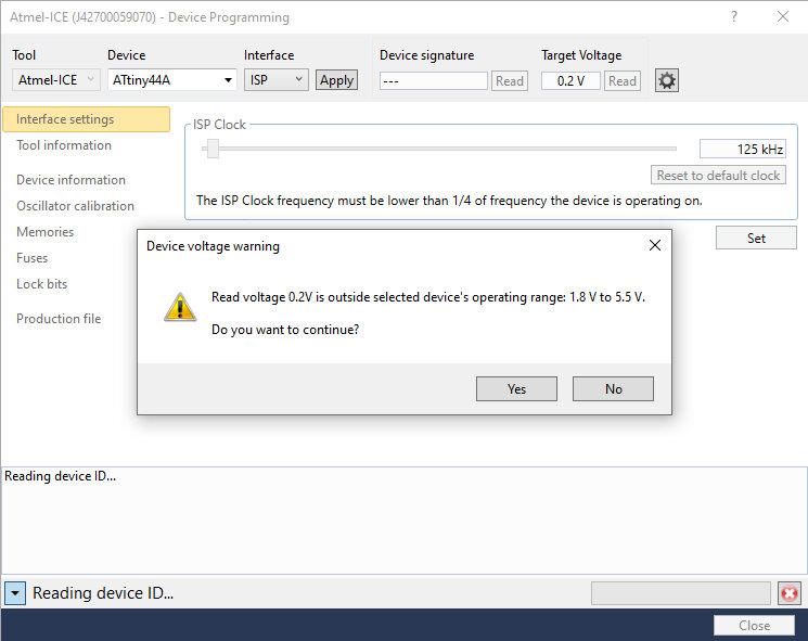
Tried to read anyways but fail.
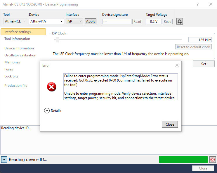
Found in an online forum that Atmel-ICE does not supply power…
Connected the VCC and GND pins from FTDI converter as the target board’s power supply and then it worked! (Green light on Atmel-ICE turned on after target board got power)
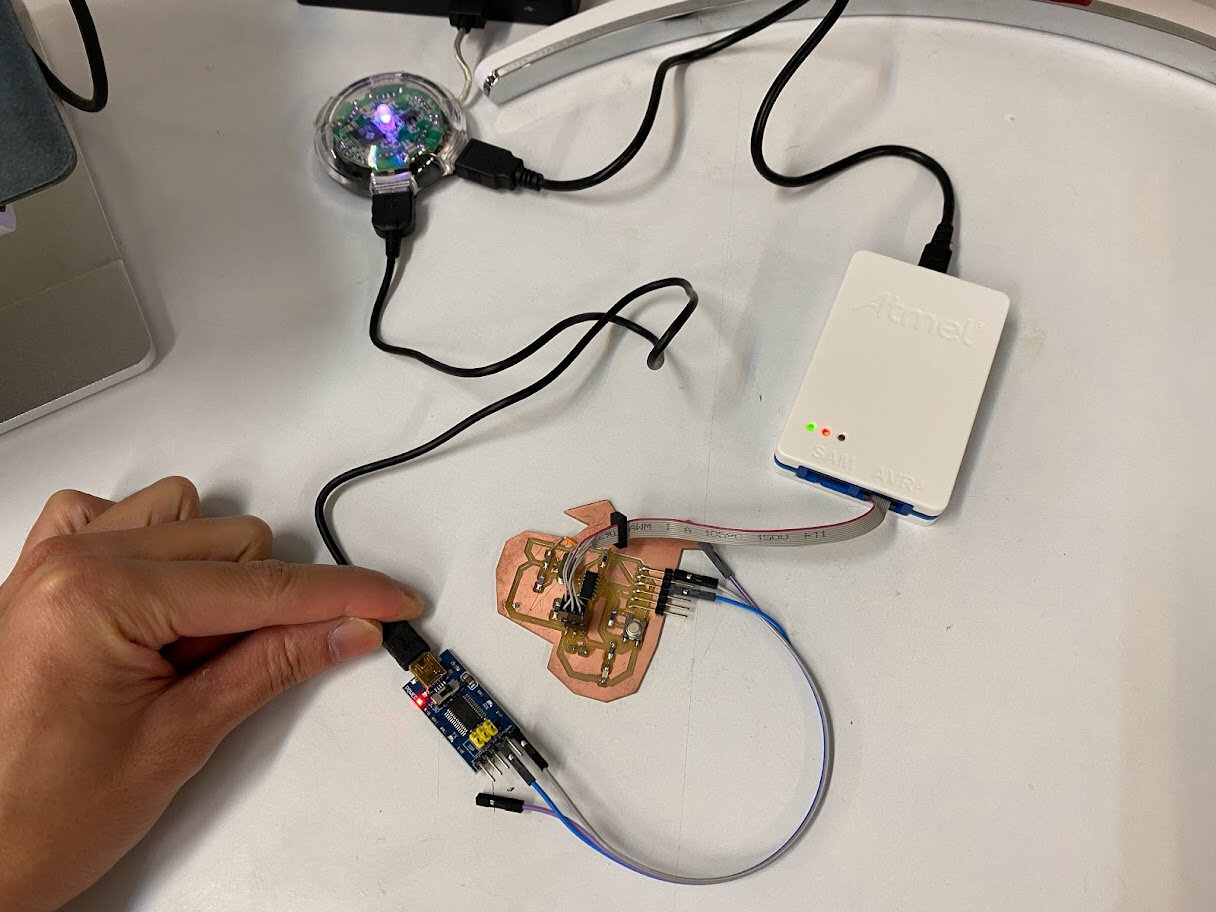
Successful read in Microchip Studio, so perhaps it’s not a problem with my hardware after all.
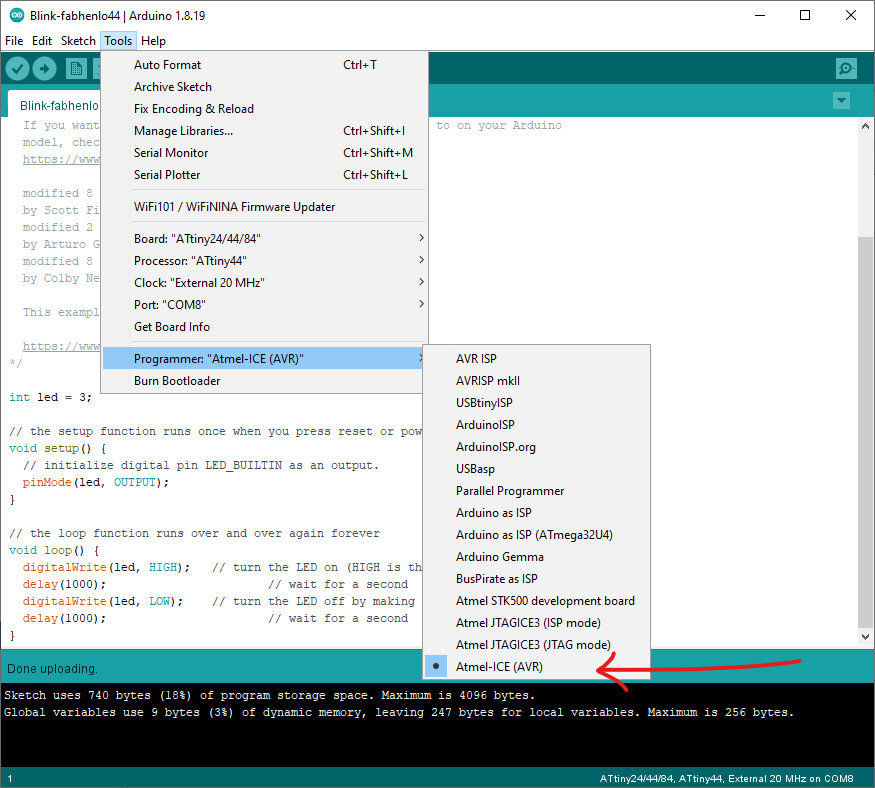
Go back to Arduino IDE, using Atmel-ICE as the programmer for now since I know this setup works. Select “Atmel-ICE (AVR)” as the programmer in Arduino IDE as shown below:
Programming Steps
The problem I was having at the end of Week 6 was that I was unsure of all the software and hardware connections steps to get the echo program to work. After attending Global Open Time, I learned the proper order:
- Hardware: Connect programmer board to target board via ISP pins. In my case I used Atmel-ICE, which doesn’t supply power, so separately connect VCC pin of target board’s FTDI to a 5V source (I used FTDI converter VCC, but could also use Arduino Uno 5V pin or any other 5V source).
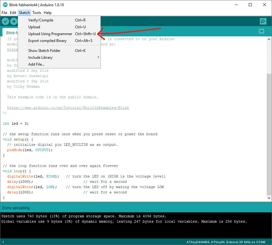
- Software: In Arduino IDE, make sure the settings under “Tools” are correct for your target board. COM port doesn’t matter here; instead of clicking the “Upload” button to flash your program (Arduino IDE calls them “sketches”), go to top menu bar “Sketch” > “Upload Using Programmer” (see screenshot below). If successful, the console should read “Done uploading.”
- Hardware: Unplug programmer board from ISP pins of target board. If haven’t already, connect ground from your 5V power supply to the FTDI connector of target board in addition to VCC. Now the target board is purely just powered on by 5V, and the program is in memory and ready to do what you programmed it to do (i.e. blink LED on button press).
- (Additional for serial comm) Hardware: if your program involves serial communication like the hello.ftdi.echo program, then you need to connect all the FTDI pins on the target board to the FTDI converter/cable that goes to your computer. Sometimes Tx/Rx connections need to be swapped so that Tx of the FTDI converter goes to Rx of the target board and vice versa, but other times, Tx and Rx on the MCU is swapped in software already (such is the case in Neil’s hello.ftdi.echo program) and so just need to connect directly! (Tx of FTDI converter to Tx of target board and same for Rx).
- (Additional for serial comm) Software: to read/write serial communication to target board such as in the case of hello.ftdi.echo, open Arduino IDE, click the magnifying glass icon in the top right and it’ll open Serial Monitor. That’s it!
Note: With a bootloader installed on a target board’s MCU, it should be possible to flash a program onto it just through the FTDI pins (instead of ISP pins) but I haven’t gotten that to work yet.
Update: Found out from Adrian Torres that ATtiny44 which I’m using is AVR 0 generation from Atmel and thus the target board I made from Week 6 can’t do programming through FTDI. Have to use another programmer like FabISP or Atmel-ICE and the ISP pins to program. Newer MCUs can program through FTDI or UPDI with a bootloader installed, will try in future.
Programming Henlo44 Board from Week 6
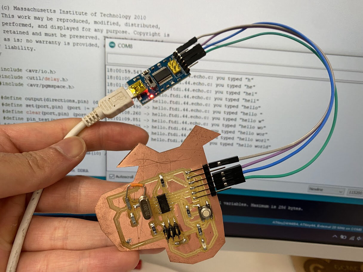
Catching up on Week 6, I first tried the hello.ftdi.echo program on my Henlo44 board again.
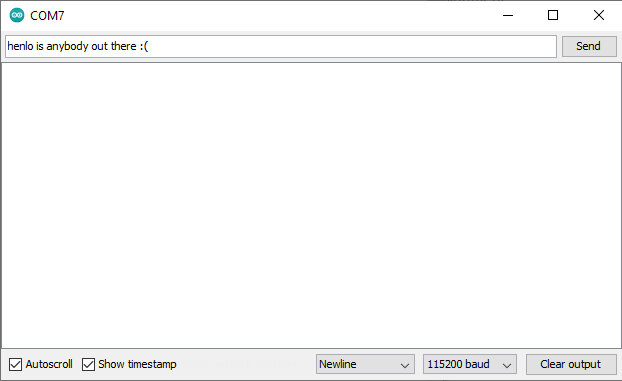
I copied hello.ftdi.44.echo.c code text into a new Arduino IDE sketch, then “Upload Using Programmer”, opened the Serial Monitor and sent some chars, and got a response! The ATtiny44a echoed back!!
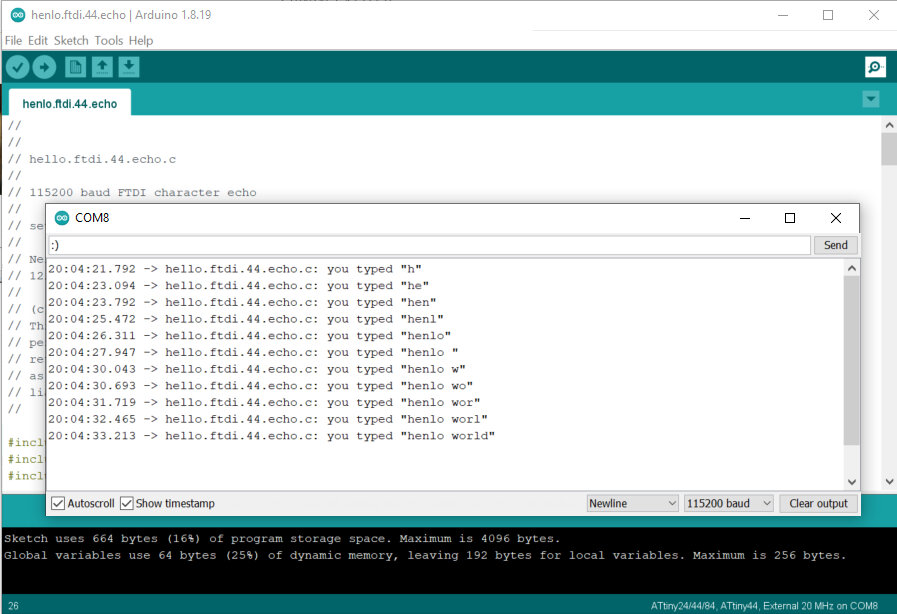
To be extra sure it was working correctly, I removed the ISP wires and saw the echo response with only FTDI connected to my board. Great success! Week 6 caught up.
Custom program
First test if my board’s LED can turn on at all with a button press input. (It does!)
Now onto something harder to program…
Morse code!
Morse code is a form of serial communication! Some interesting history, one could say it was actually the first type of serial communication to ever go through a wire (telegraph technology in the 1800’s). Of course there were no “computers” back then, humans on both ends of the telegraph wire acted as the compiler and decoder of this serial communication of “1s and 0s” (beep vs. no beep) encoding English words and numbers. Let’s pay homage to Thomas Edison and this important historical technology with some modern code!
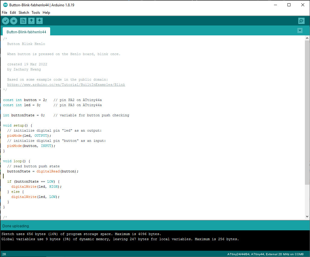
For my button blink coding, I made the MCU send out a string of Morse code with LED blinks when it detects an input button press.
“Henlo World” in Morse code blinks
Button Blink Henlo Code
/*
  Button Blink Henlo

  When button is pressed on the Henlo44 board, blink and stuff.

  created 19 Mar 2022
  by Zachary Hwang

  Based on some example code in the public domain:
  https://www.arduino.cc/en/Tutorial/BuiltInExamples/Blink
*/

const int button = 2;   // pin PA2 on ATtiny44a
const int led = 3;      // pin PA3 on ATtiny44a

// Morse Code timing setup
/*
The Morse code rules for signaling are:

a dot lasts for one second
a dash last for three seconds
the space between dots and dashes that are part of the same letter is one second
the space between different letters is three seconds
the space between different words is seven seconds
*/

const int unit = 75;   // base time unit for morse code, smaller is faster baud rate; equivalent to "one second" in signal rules^
const int dot = unit;
const int dash = unit * 3;
const int space = unit;
const int char_space = unit * 3;
const int word_space = unit * 7;

int buttonState = 0;    // variable for button push checking

void setup() {
  // initialize digital pin "led" as an output:
  pinMode(led, OUTPUT);
  // initialize digital pin "button" as an input:
  pinMode(button, INPUT);
}

void loop() {
  // read button push state
  buttonState = digitalRead(button);

  if (buttonState == LOW) {
      h();
      e();
      n();
      l();
      o();
      _();
      w();
      o();
      r();
      l();
      d();
      _();
  } else {
    digitalWrite(led, LOW);
  }
}

// morse code letter functions

// "_" is function name used for spaces in between words. Every char already ends with a char_space of 3 time units.
void _() {
  delay(word_space - char_space);
}

void d() {
  digitalWrite(led, HIGH);
  delay(dash);
  digitalWrite(led, LOW);
  delay(space);
  digitalWrite(led, HIGH);
  delay(dot);
  digitalWrite(led, LOW);
  delay(space);
  digitalWrite(led, HIGH);
  delay(dot);
  digitalWrite(led, LOW);
  delay(char_space);
}

// ... other letters' functions below trimmed off for brevity, they all have similar structure
I realize my code could’ve been “cleaner” or more “beautiful” if I had made functions instead for dot and dash and the appropriate spaces following letters and words, but this worked for testing and can always optimize later!
Programming with self-made FabISP
The ultimate goal of this assignment is to program our own target boards using our own programmer boards that we made ourselves. Henlo44 board was programmed successfully with a commercial Atmel-ICE programmer, but let’s see if we can do the same with a FabISP made in Fablab Taipei!
Since Week 4 ended in failure and troubleshooting was fruitless after hours of debugging, I decided to just start over from scratch.
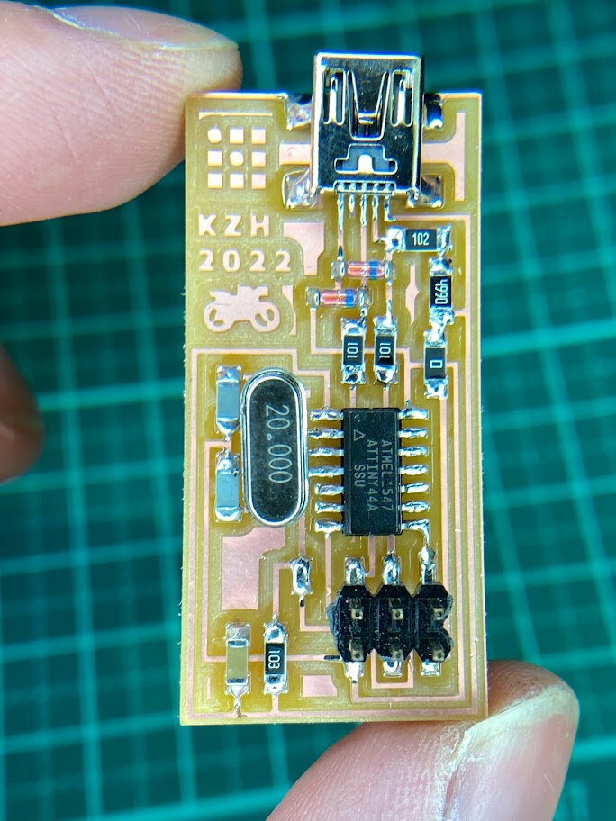
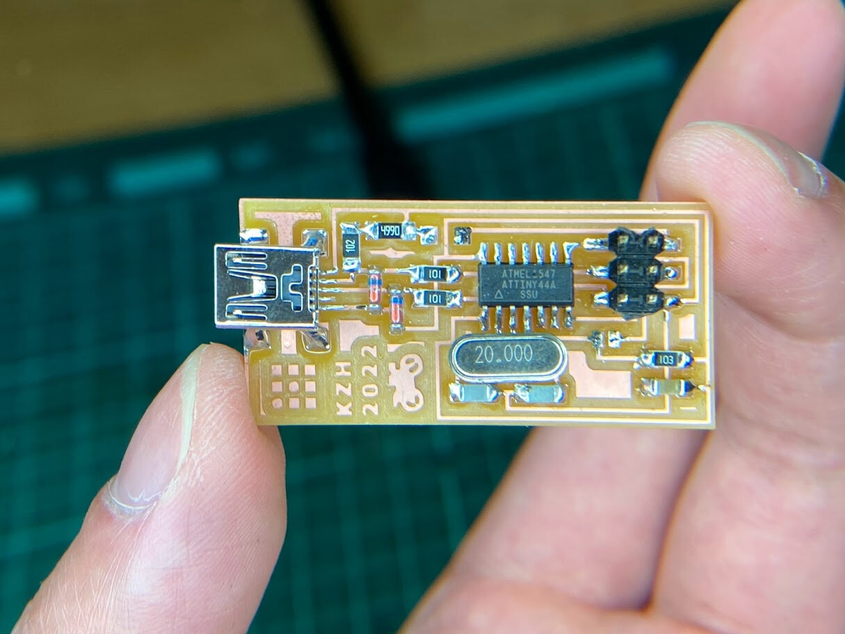
Made a new FabISP board, and this time went much faster and smoother with some experience milling and stuffing boards under my belt! And my soldering was a lot cleaner and prettier this time too :)
FabISP #2 - KZH 2022
Following another tutorial for FabISP this time.
I also realized I was working with an old version of avrdude, version 5.11 from 2011. It didn’t even list the Atmel-ICE board in it’s programmer list! That’s how old that version was. (facepalm)
No wonder it never worked when I used “atmelice_isp” as the programmer name when following other tutorials.
I had previously downloaded avrdude from a link in an old documentation, so this time I went straight to the source and updated my avrdude to version 6.4. Much better!
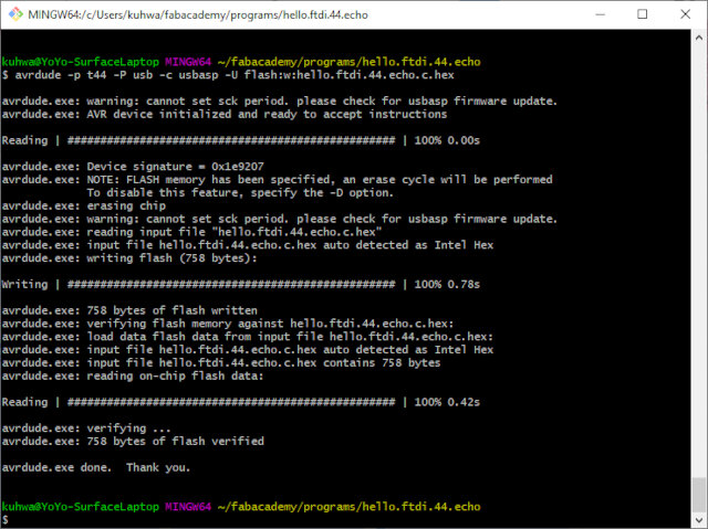
Initializing programmer and target MCU with avrdude in Git Bash.
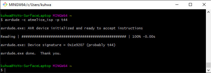
Git Bash into the folder containing the unzipped firmware for the ATtiny44a. Make sure Makefile is updated using the correct Programmer name. Mine was atmelice_isp.
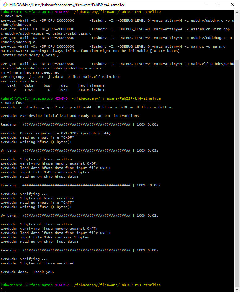
Make .hex file from .c file and Makefile using “make hex” command. Then run “make fuse”.
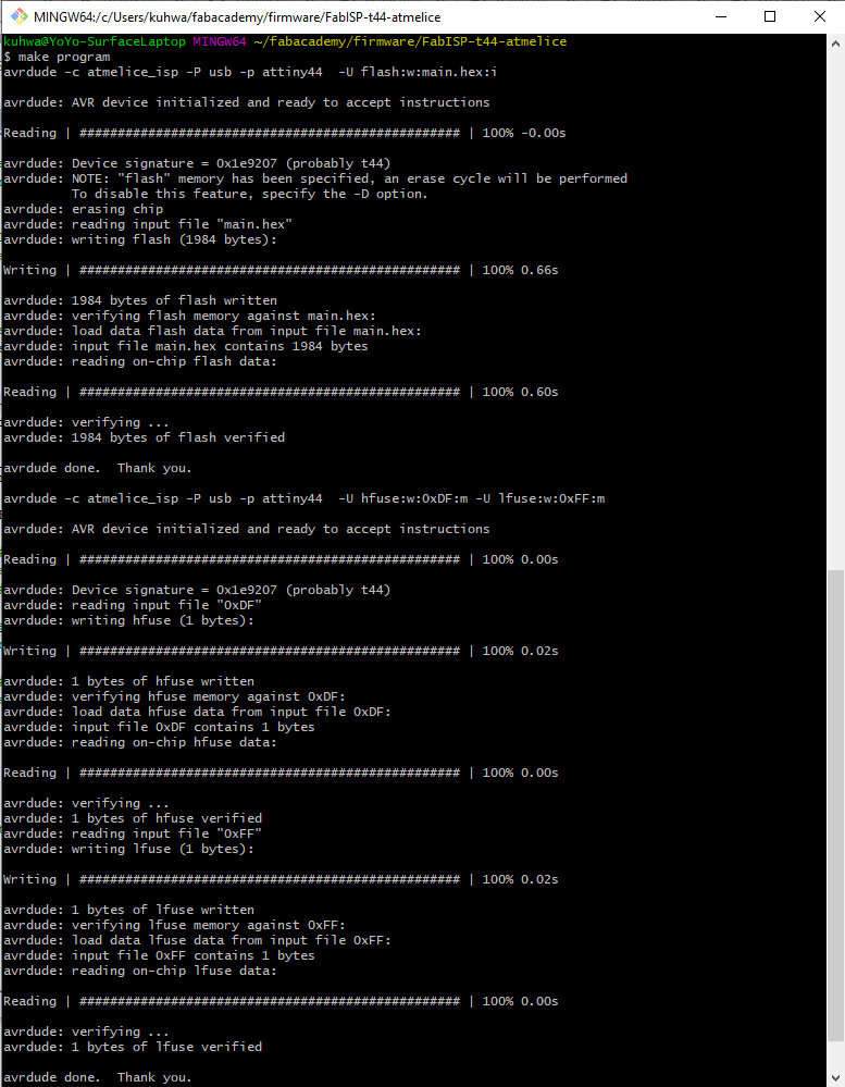
Finally, run “make program”.
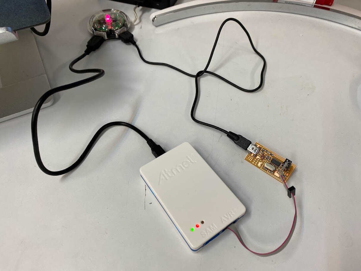
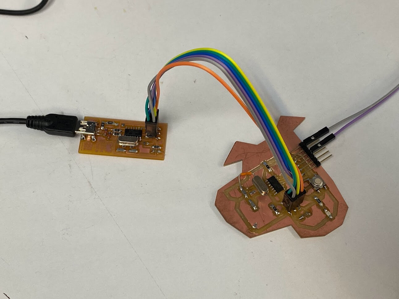
Correct FabISP and Atmel-ICE hardware setup for programming firmware and other programs.
Check Device Manager after the last “make program” step. Success! It shows up correctly!
To make it into a programmer, last step is to desolder the solder bridge and 0 Ohm resistor jumper. Now it’s official!
Week 4 all caught up!
Proof of programming with self-made FabISP
Putting it to the real test…
Initial program makes MCU output “SOS” Morse code in the LED blinks, flashed new uploaded program via FabISP programmer, MCU now outputs “Henlo World” in Morse code LED blinks! Great success!!
Hero shot: self-made programmer programming self-made target board
Group Assignment - Test other architectures
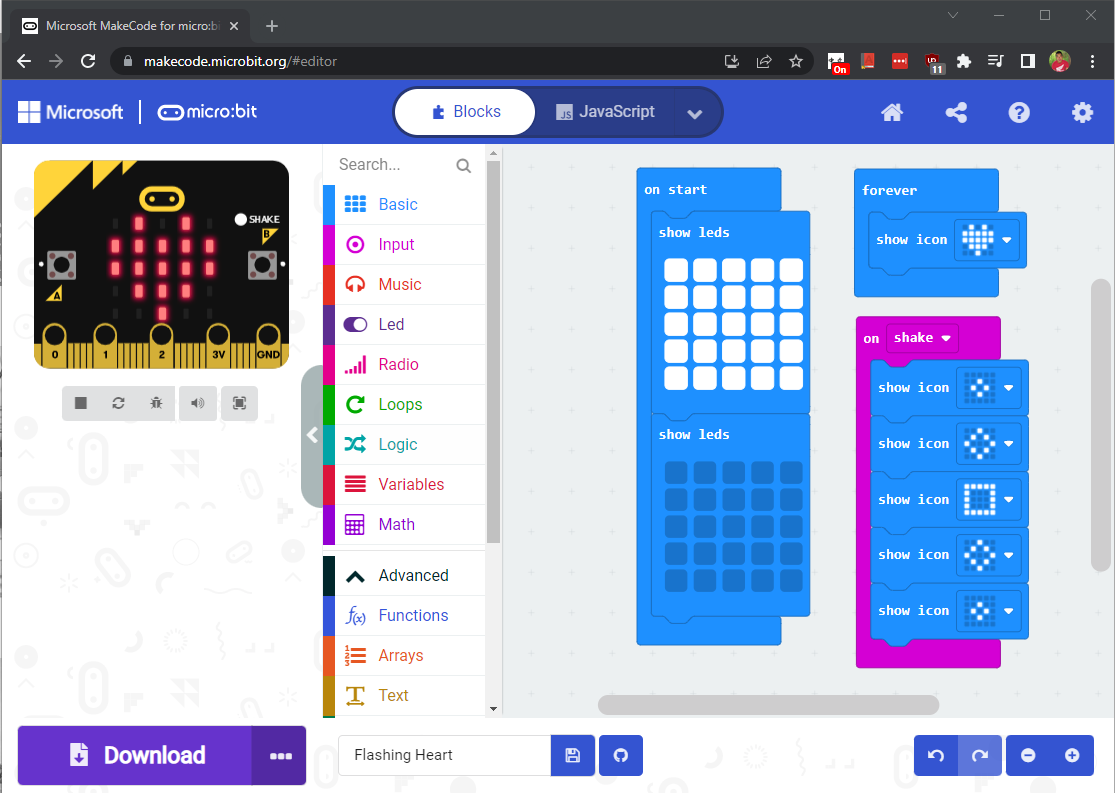
In a previous job I was involved in STEM education for kids, so I have a lot of experience building little projects with micro:bit and MakeCode. I would’ve liked to do something more advanced for this week with Raspberry Pi which we have available in the lab but ran out of time. My classmate used the same MCU and workflows (Arduino IDE, and avrdude+terminal) so we didn’t have anything to compare in that regard.
Here’s a screenshot of the MakeCode IDE (made by Microsoft) for the micro:bit (essentially an Arduino board for kids).
Conclusion
As a beginner to this world of embedded systems and embedded programming, I found it really hard to pick up at first, just like picking up a new language that has no similar roots to what you knew before, like learning Chinese as a native English speaker. Programming is essentially it’s own language, with it’s own grammar and rules (syntax), and way of thinking embedded (pun intended) into it’s language. On top of that there’s the whole hardware world that it lives in with tons of acronyms and technical concepts.
Having spent years of my life learning Spanish and Chinese as second languages, I am kind of familiar with this feeling and process. You just have to learn one thing at a time, look up one word at a time, one rule at a time. Then connections are made backwards, and one day you realize you’re more fluent then you were before and everything you learned along the way is connecting; dots only connect in hindsight.
In the real world, you’re just thrown in the deep end; basically what Neil is doing to us with this MIT-style course. You move to a new country and everyone around you is using the FULL language- you are exposed to words from Level 1 to Level 6 (comparing with Chinese HSK learning standard), and you don’t know if the words you’re hearing are Level 1 or Level 6. But you grab what you can and start there.
“You can’t connect the dots looking forward; you can only connect them looking backwards. So you have to trust that the dots will somehow connect in your future. - Steve Jobs
There were SO many acronyms this week and specialized jargon that it makes you feel like you have no idea what’s going on, and even a bit stupid sometimes. I still feel like there’s a whole universe I don’t understand inside these MCUs but I’ve picked up a bit of the language as a beginner.
For example, I kept hearing “FTDI”, so I Googled it. Still confused. Made no sense to me and could not connect how the instructors were using that word and concept. So kept digging and going deeper into the wikipedia and forums rabbithole. Stumbled upon this really helpful YouTube video explaining what is Serial Communication (shown below). Side note: There’s actually a ton of helpful youtubers making videos about this electronics world!
Now FTDI and other things are starting to make a bit more sense, and when an instructor said to me “After flashing hello.ftdi.echo onto your MCU, unplug the ISP, connect the FTDI pins through a USB to UART converter to your computer and read the serial output in Serial Monitor of Arduino IDE and make sure to change the baud rate setting.” I was like, “Uh huh, yup got it” and went and did it and IT WORKED. A month ago I had no idea what ANY of those words meant. These little moments are really gratifying to a learner of language, or technology, or anything! So as Dory said in Finding Nemo, “just keep swimming” :)
Things I want to try in the future with more time
- FTDI serial output from Henlo44 board when button pressed
- PlatformIO (generalized form of Arduino)
- ARM architecture: SAMD11C
- FPGA
- ESP modules with built-in networking (Wi-Fi/Bluetooth)
- MicroPython
- TinkerCAD circuit simulator
- Beagle board AI kit
- Raspberry Pi programming
Useful links
- What is an embedded system?
- Are 8-bit microcontrollers still relevant?
- Arduino as ISP and Arduino Bootloaders
- FTDI vs. AVR Programmer
- How to program an AVR Microcontroller using Atmel Studio
- ATtiny microcontroller comparison chart