5. 3D Scanning and Printing
Group Assignment:
- Test the design rules for your 3D printer(s)
Individual Assignment:
- Design and 3D print an object (small, few cm3, limited by printer time) that could not be easily made subtractively
- 3D scan an object, try to prepare it for printing (and optionally print it)
Learning Outcomes
Identify the advantages and limitations of 3D printing
Apply design methods and production processes to show your understanding of 3D printing
* Demonstrate how scanning technology can be used to digitize object(s)
3D Printer Design Rules
For full characterization of Fablab Taipei’s 3D printers please see the group assignment site.
Fablab Taipei 3D Printers
| Manufacturer | Model | Printer Type | Made in |
| ----- | ----- | ---- | ---- |
| Creality | Ender-3 | FDM | Shenzhen, China |
| Anycubic | i3 Mega S | FDM | Shenzhen, China |
| Phrozen | Make | SLA** | Taiwan |
FDM - Fused Deposition Modeling (laying down tiny spaghetti noodles of plastic)
*SLA - Stereolithography (pulling an object out of resin while using light to cure an entire layer at once)
We didn’t have resin readily available for the Phrozen machine, so for our design rules investigation and individual assignments we only used the FDM printers this week.
Intro to the 3D Scanning and Printing Process
The process starts with a digital file that represents a 3D object digitally. This 3D object can be either designed from scratch in a CAD program or come from a real physical object scanned into the digital world via different 3D scanning technologies.
Let’s take a look at the following example of a simple sphere.
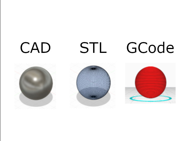
CAD
When designing from scratch, the 3D object is expressed numerically by the CAD program. The geometries are perfect mathematical descriptions and in the case of this sphere, the CAD program can describe it with the following equation:
(x – a)² + (y – b)² + (z – c)² = r²
Of course, more complicated shapes can be made by adding together, subtracting, or even following paths to generate interesting shapes, but fundamentally all these CAD shapes boil down to these building block geometries with simple mathematical descriptions and operations around them.
STL
Another way to describe a 3D object digitally is called a “mesh”. This refers to mapping out the surface contours of a given 3D object using a web of triangles. This is not a perfect representation of the objects (analogous to vector vs. raster in 2D graphics) but nonetheless has it’s applications and is more practical to use in different cases. The common format for meshes is called STL, and is what is exported from CAD programs when we want to prepare for 3D printing.
In an STL file, the surfaces of those perfect CAD geometries are approximated with triangles.
In 3D scanning, we go straight to this step- the result of the 3D scanning software is a mesh output that is commonly in .stl format. (Others formats exist such as .3mf and GLTF)
G-code
G-code is a set of instructions for the 3D printer to follow. It can be thought of as a path for the tool, AKA a toolpath. We go from STL to G-code using a “slicing” software such as Cura, which takes into account printer and material settings, and generates the algorithm to follow to physically print out the 3D object described in the STL file.
Typically, G-code instructions are layer-by-layer with 2D layers added on top of each other, although there’s some cool research for non-planar g-code; imagine the 3D printer head drawing in 3D curves as an artist would instead of mechanically putting down 2D layers.
An example of G-code will be shown below, but let’s jump into the assignment first.
Designing a Unique Additive Manufacturing Object
This week’s assignment was to demonstrate the unique capabilities of 3D printing by designing an object that could not be easily made with subtractive manufacturing (i.e. CNC milling).
So, I decided to make a simple object that had 2 pieces, printed at the same time, that would not be able to be separated, which also meant that it would be impossible to machine these two pieces separately and then combine them using traditional manufacturing methods.
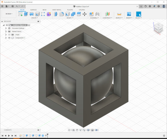
My final idea was a sphere in a cage, where the sphere is intentionally too large to take out of a cage.
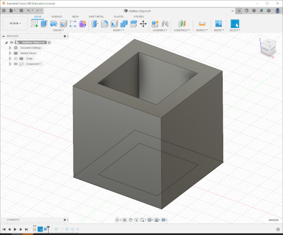
Sketching in Fusion 360
Started with a simple sketch for base of the cage.
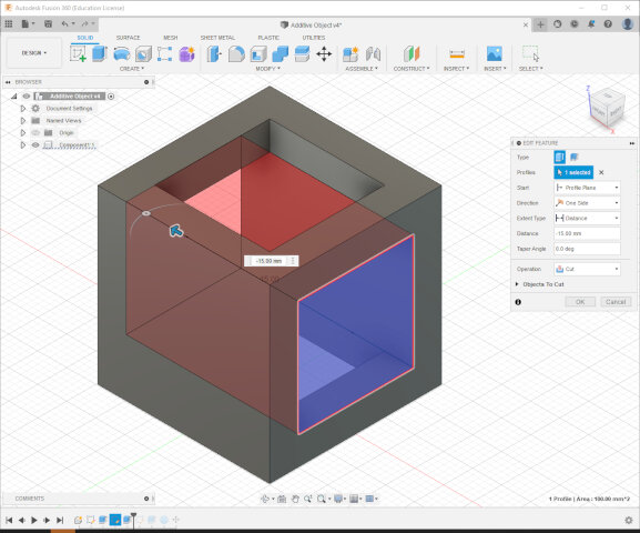
Extrude out a hole in another face.
Extrude out the other face and add a sphere.
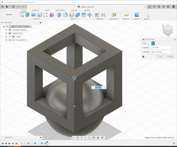
Move the sphere to the center and ensure the sides are not touching. We want the sphere to freely spin inside to prove they are indeed two pieces!
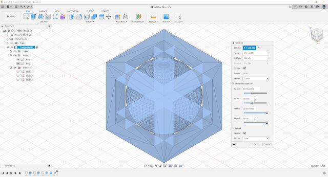
Export the whole design as an STL. Here you can see a preview of the mesh (notice how there are only triangles!)
Cura slicing software
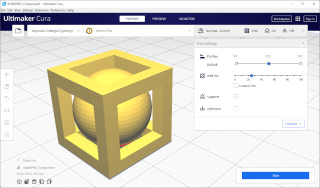
Import STL into Cura.
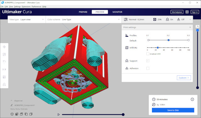
Cura generating toolpath G-code including instructions for support structures. The top bars of the cage will droop during printing without these supports. There are also squiggly supports at the bottom of the sphere to hold it together to the printer bed as the sphere takes shape layer-by-layer when starting out.
The following is a sample of the G-code that Cura outputted to print out this design on an Anycubic i3 Mega S.
AI3MSPRO_Component1.gcode
;FLAVOR:Marlin
;TIME:1433
;Filament used: 0.86103m
;Layer height: 0.2
;MINX:92.434
;MINY:92.521
;MINZ:0.3
;MAXX:117.574
;MAXY:117.479
;MAXZ:15.175
;Generated with Cura_SteamEngine 4.13.1
M82 ;absolute extrusion mode
G21                                        ; metric values
G90                                        ; absolute positioning
M82                                        ; set extruder to absolute mode
M107                                       ; start with the fan off
M140 S60           ; Start heating the bed
G4 S60                                     ; wait 1 minute
M104 S210         ; start heating the hot end
M190 S60           ; wait for bed
M109 S210         ; wait for hotend
M300 S1000 P500                            ; BEEP heating done
G28 X0 Y10 Z0                              ; move X/Y to min endstops
M420 S1                                    ; Enable leveling
M420 Z2.0                                  ; Set leveling fading height to 2 mm
G0 Z0.15                                   ; lift nozzle a bit
G92 E0                                     ; zero the extruded length
G1 X50 E25 F500                            ; Extrude 25mm of filament in a 5cm line.
G92 E0                                     ; zero the extruded length again
G1 E-2 F500                                ; Retract a little
G1 X120 F4000                              ; Quickly wipe away from the filament line`
G92 E0
G92 E0
G1 F1500 E-6
;LAYER_COUNT:75
;LAYER:0
M106 S76.5
M205 X10 Y10
G1 F600 Z0.375
G0 F6000 X102.97 Y94.153 Z0.375
M205 X8 Y8
;TYPE:SKIRT
G1 F600 Z0.3
G1 F1500 E0
G1 F1200 X103.015 Y94.121 E0.00275
G1 X107.597 Y94.121 E0.23135
G1 X107.642 Y94.247 E0.23803
G1 X107.597 Y94.279 E0.24078
G1 X103.015 Y94.279 E0.46938
G1 X102.97 Y94.153 E0.47605
...
3D Printing
G-code sent off to the Anycubic printer!
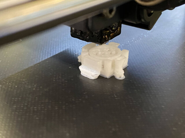
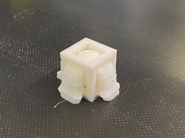
Removed supports carefully with a needlenose plier and exacto knife. Cura designed these supports to be relatively easy to remove, with “light contact” at the supporting areas.
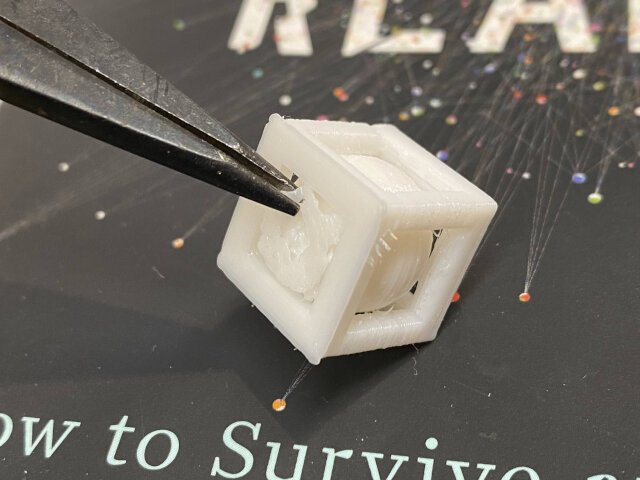
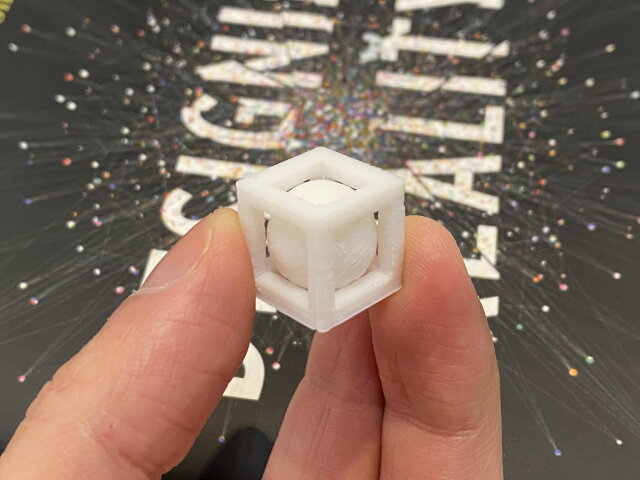
Completed! The sphere can freely spin inside and also cannot be removed from the cage, achieving the design goal.
3D Scanning with Polycam
For this week’s 3D scanning assignment I first used Polycam, an iPhone app for 3D scanning that uses photogrammetry, a variation of which is taking a bunch of 2D pictures and using computational models to extrapolate a 3D object from them.
The following 3D model of my Kawasaki Ninja toy was scanned with an iPhone 11 Pro.
Feel free to click and drag on the model to move it around!
Even all the scratches from my childhood driving and crashing were faithfully reproduced digitally! XD
Note on iPhone cameras
The newer iPhone 12 and 13 Pro models have a depth sensor called Time of Flight (ToF) sensor. ToF is similar to LiDAR, they both generate 3D maps of real world objects using light reflections. iPhone 11 Pro doesn’t have ToF so this 3D model was created purely with 2D images. Polycam does have a mode that can use a phone’s ToF sensor, which I imagine makes the result even more accurate. But nonetheless I thought the result was quite impressive!
Some notable imperfections though: * Glob of white under the motorcycle by kickstand where AI probably got confused what is clear or not * Globs of white around front and rear tires * Exhaust pipe not fully straight, reflective surface maybe didn’t help
Polycam has a pretty neat Augmented Reality (AR) feature within the app. In the video below I “placed” a digital clone of the Ninja toy next to the real thing; it almost looks like there’s two real ones until the left camera angle makes it apparent one’s fake with some unrealistic clipping going on:
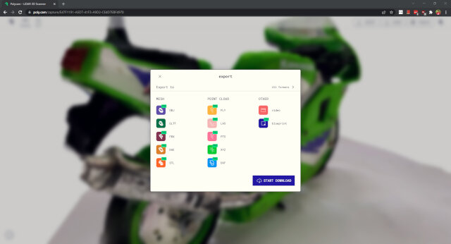
Next step exported from Polycam to GLTF format (only format available for free).
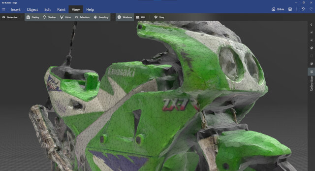
Tried to edit the GLTF (appears as a “.glb” in file explorer), Windows suggested 3D Builder by microsoft, which got decent reviews in the Windows Store so figured I’d try this software for free. Can’t do much in it, was hoping to remove some extraneous bumps particularly in the base of the Ninja Toy scan which I didn’t want printed, but 3D Builder is very simple and can only apply broad changes to the whole object such as smoothing, etc.
It does show wireframe though, which is cool and this is what I mean by STL files being a superficial mesh made up of little triangles!
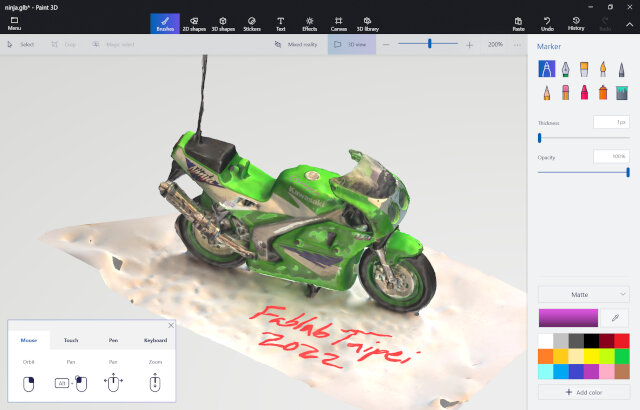
Quickly tried 3D Paint (also built-in with Windows) but again no luck. 3D Paint is also quite basic- you can paint (duh) in 2D and also onto 3D objects. But it won’t let you edit the mesh and shape of an existing 3D object.
For this advanced function to clean up a model I thought Blender would be the ideal software to edit this 3D Ninja Toy object. However, upon attempting to open the file I found out Blender does not support .glb files unfortunately.
Polycam does export in other formats in PRO mode, such as OBJ and STL directly, which would make editing out and fixing unwanted features a lot easier. But I’m on a budget and not trying to pay for that right now heh sorry.
Went ahead and printed as is with Cura anyways. Cura can open the GLTF directly and though there were some messy bits from the imperfect scan, it seemed printable so gave it a shot.
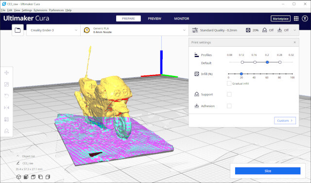
Needed some supports for the upper parts of the body and gaps such as between handlebars and windshield.
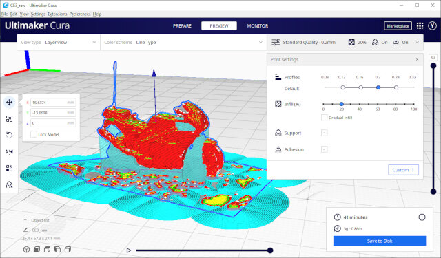
Exported the G-code for the Creality Ender-3 printer and sent it off!
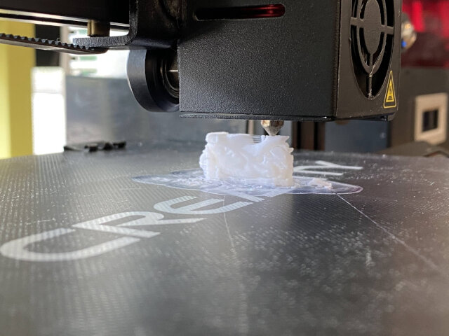
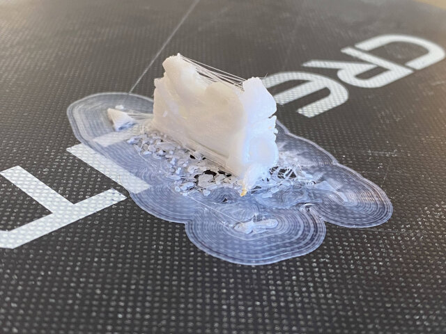
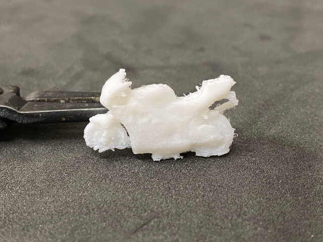
The bumps in the base that I couldn’t remove caused some rough issues with the initial layers sticking the printer bed. The front wheel did not make it out unscathed.
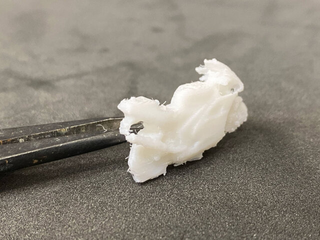 Nonetheless, it was not bad for a direct print of a photogrammetry scan without any cleaning! The supports worked surprisingly well and the details of negative space around the handlebars and the exhaust pipe can be appreciated.
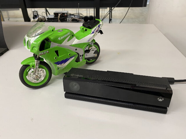
3D Scanning with Kinect (V2)
I have an Xbox One at home with the Kinect V2 camera. This is upgraded hardware from the Xbox360 and Kinect V1 camera, but I later found out it’s not necessarily better!!
But let’s give it a shot to 3D scan the same Ninja Toy and compare the quality of the results with Polycam.
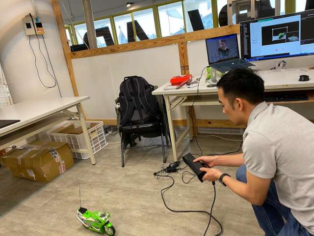
The only 3D scanning software that works with Kinect V2 is 3D Scan, another software made by Microsoft. Super basic and cannot do much besides scanning with basic adjustments. You can see it on my screen in the background here:
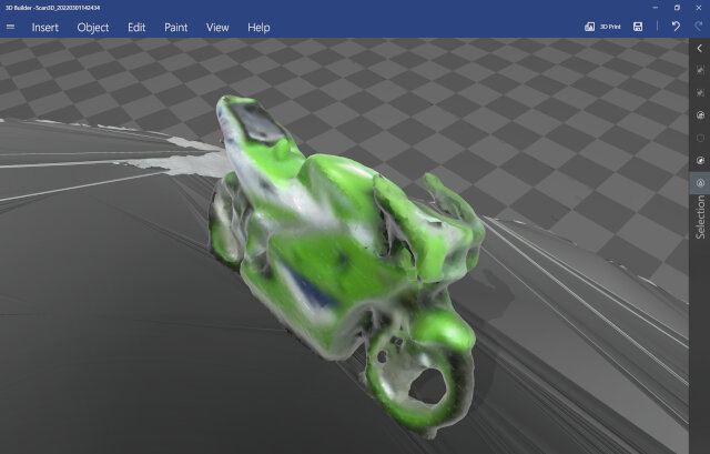
The result from the Kinect scan was quite poor. Even with supposedly superior hardware compared to a regular iPhone camera, the 3D model was very lacking as you can see below. The windshield of the motorcycle is completely missing and I hypothesize it’s because the Kinect’s depth sensor just saw right past it and thought it was empty space. However, it’s obviously not clear and scratched up, so the iPhone + Polycam picked this up much better.
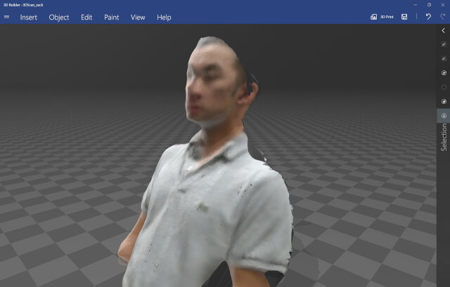
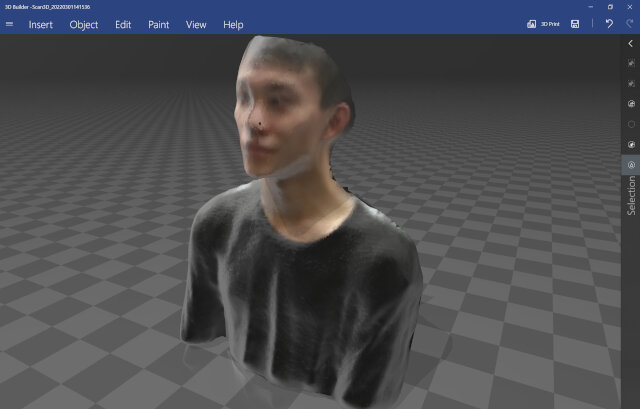
Classmate Hanson and I took turns scanning ourselves with the Kinect V2 camera as well, we faced the Kinect sitting in a spinny office chair and slowly rotated side to side a few times. The results were somewhat creepy lol.
Kinect thoughts
Originally a camera accessory for Xbox video games, featuring depth sensors for interacting with games using human body i.e. Just Dance, hackers found it useful as a 3D scanner because of it being a relatively low-cost camera with depth sensing.
Software looked into for connecting Kinect camera to PC for 3D scanning: * OpenKinect * ReconstructMe * Skanect
ALL of these support the original Kinect V1 but not Kinect V2. Seems Microsoft did not like all the hacking of their V1 hardware so V2 was designed to be more restricted.
Now Kinect has been discontinued as an Xbox accessory (sad!) but the Kinect lives on with a newly announced “V3” called Azure Kinect DK. Website says it’s an “Open Software Ecosystem” but its quite obvious Microsoft prefers you to integrate your application with their Azure cloud service for your 3D scanning/machine vision projects.
Conclusion
- 3D printers can do a lot and make things that are very difficult to make subtractively but still have limitations
- Photogrammetry is very powerful (Polycam, Meshroom, other apps)
- ToF or LiDAR sensors can make cameras even better at 3D scanners, like newer iPhones
- Kinect V2 is not good hardware for 3D scanning because of software constraints
- Other commercially available 3D scanners will definitely perform better such as the Revopoint (which was delayed in shipping getting to our Fablab this week)
Future Exploration
With more time I would like to:
- Try SLA 3D printing with our Phrozen Make printer.
- Dive more into Kinect V2 hacking potentially with OpenKinect
- Try out AliceVision Meshroom open-source 3D scanning
- Try out Qlone 3D scanning app
- Scan my life-size Kawasaki Ninja for future mods
- Try out Revopoint 3D scanner
Useful links
Design Files
- Sphere in Cube - Fusion360 STP file
- Polycam Ninja Toy scan viewer
- Ninja Toy scan GLTF output file
- Ninja Toy Gcode for Ender-3 printing