2. Computer-Aided Design
Assignment
- Model (raster, vector, 2D, 3D, render, animate, simulate, …) a possible final project, compress your images and videos, and post it on your class page
Learning outcomes
Evaluate and select 2D and 3D software
Demonstrate and describe processes used in modelling with 2D and 3D software
2D Raster Drawing (GIMP)
GIMP was suggested as a good alternative to Photoshop. It is open source and free.
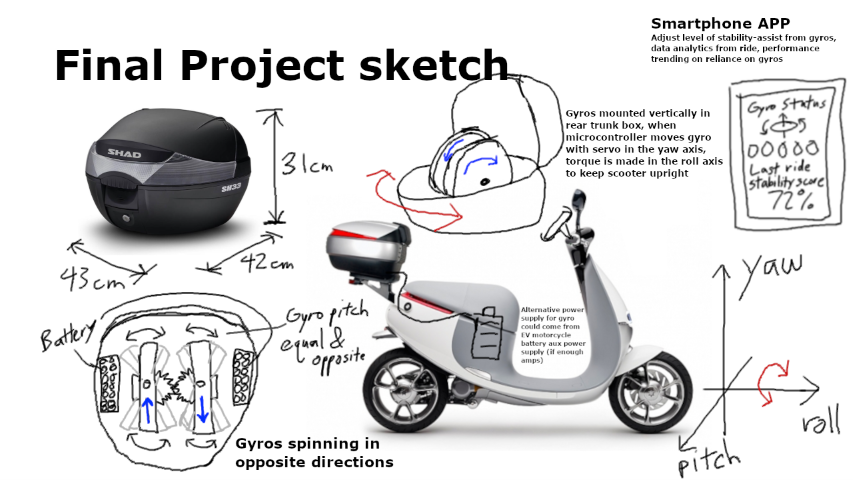
I began by sketching a potential application for my final project about control moment gyros. Scaling up the gyro, I thought it might have more commercial use in helping a human-sized motorcycle stay upright, and thus be an aid for those learning to ride scooters or motorcycles for the first time.
Using GIMP at first was a bit clunky, I used it on my Microsoft Surface Laptop (touchscreen) with a Surface Pen. The brush tool was not very smooth with the pen, especially compared to native Windows apps like MS Whiteboard. However, GIMP has more professional features like layers, which help control a messy sketch/project idea board which my drawing turned out to be.
Note: in GIMP, every text box becomes a new layer! Make sure you’re “in” the right layer when trying to draw or move objects around. As a newbie, this was one frustrating part to get used to.
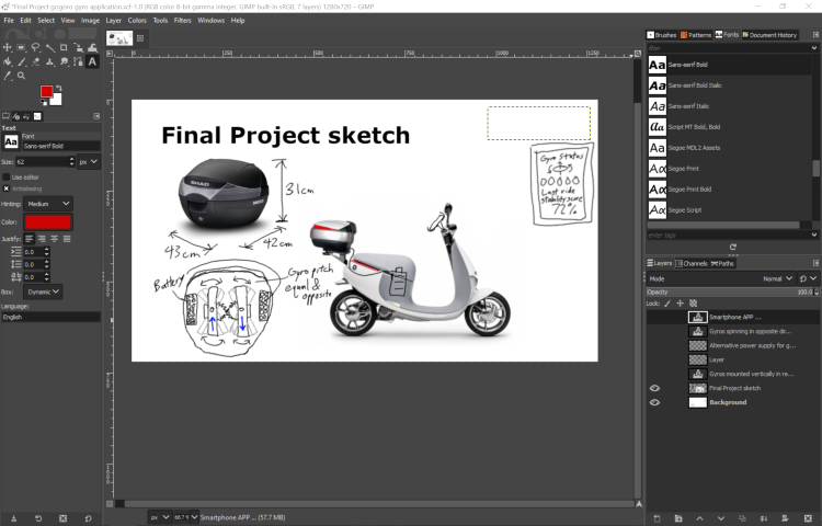
Here’s my final sketch. It’s a combination of pictures from the internet, my own hand drawn diagrams, notes, and input text boxes. I think next time for quick idea jotting, I will still stick with MS Whiteboard. GIMP is not as nice to use because the text boxes are difficult to work with.
2D Vector Drawing (Inkscape)
First time doing vector drawing, decided to go with the free Inkscape software. It’s also open-source which I like to support.
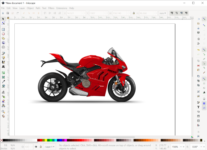
My idea for a fun vector drawing practice was to make a logo for my motorcycle club here in Taiwan.
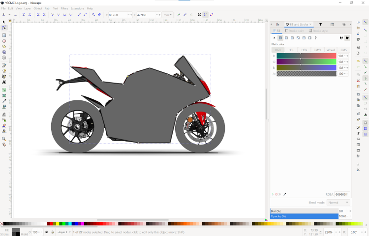
Step 1, import side profile picture of a Ducati Panigale V4.
Lock layer 1 with Ducati picture, removes dragging option for easier handling when drawing on top; start with wheels, drawing 2 circles each and creating a path of difference to “cut out” the inner circle. Aligned with straight line at bottom (made by holding down ctrl while drawing)
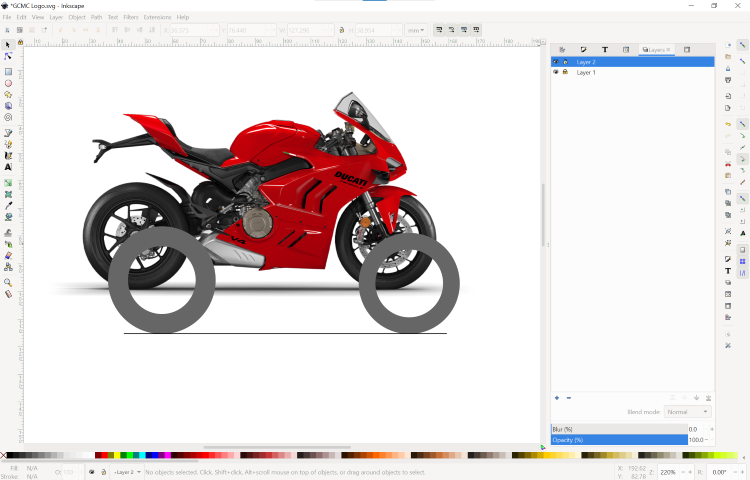
First spiral, use connecting lines to make a rough shape of Ducati body, see how the fill and stroke features worked.
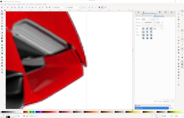
Go back in and do detailed adjustments to the line (Bezier curve), can add additional nodes after original curve is made for more fidelity and control. LOTS and LOTS of nodes, took a lot of time to adjust node positions and Bezier handles to adjust the curvatures to match the underlying ducati picture
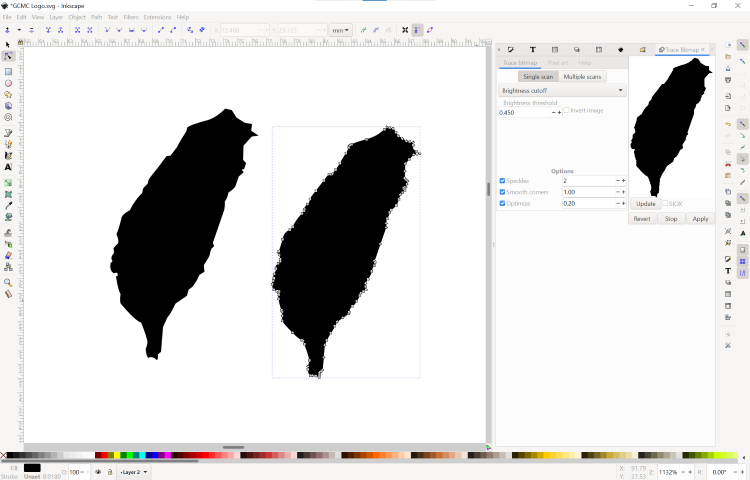
Since motorcycle club is based in Taiwan, wanted to add a map of Taiwan cutout to my vector drawing. Found a png online but png cannot be used in a Path > Difference “cut”. Figured out how to convert png to a svg using the Trace Bitmap tool. Lots of options to select, but default settings worked fine for me and achieved indistinguishable difference to me from the PNG.
Almost done. Lots of objects towards the end making it messy. Open the Objects window to see everything and rearranging them around in terms of what should be “on top” in Layer 2. All the silhuotte tracing lines were grouped together and then fill and stroke colors could be controlled together easily.
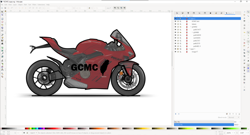
Final step was to hide Layer 1 which contained only the Ducati image, then perform cutting out “GCMC” and the Taiwan map vector object from the body of the drawing. Again used Path>Difference to do this. I tried to do a Difference with all 3 of the objects selected but Inkscape got confused and deleted everything that way. So undo, and then select them in pairs one at a time, this way the software won’t be confused about what you’re trying to cut out from what. ; another thing that confused the software was selecting the grouping previously made, Inkscape didn’t like that, you have to select the vector object within the group that you want to cut out from.
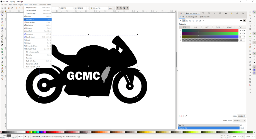
Final result!

3D Model Drawing (Fusion 360)
I previously worked with Solidworks a little bit during college a long time ago. Neil said finding the right one is like dating, so this time I decided to start by “dating” a different CAD software I’m unfamiliar with.
The main 4 options presented to Fab Academy students which are either free or educational licenses are provided for us are: - FreeCAD - OnShape - Solidworks - Fusion 360
All are parametric, algorithmic, and extensible- the basic requirements of a CAD software for Fab Lab.
For this week’s assignment I’m going to start with Fusion 360, since it’s made by Autodesk one of, if not the largest CAD software makers and used a lot in the engineering industry. It’s usually very expensive too. Next year when our education licenses run out, I will try if I can get by with FreeCAD, which is well, free. I may consider OnShape in the near future if there is a collaborative CAD project to do since that is there specialty, a browser-based “multiplayer” CAD like Google Docs but for CAD. But for now, I’m just working on my own for my Fab Academy final project so let’s jump into Fusion 360!
Fusion 360 Let’s start by making the first spiral in developing the final project. The highest risk component in it is definitely the gyro and self-balancing feature.
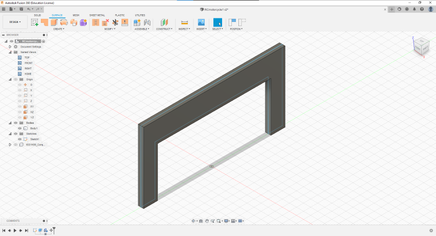
Startup Fusion 360 and start with a simple sketch for a frame we can test a gyro on. Keep it simple, no wheels for now, just two inline “feet” with a body in the middle that can mount a gyro on.
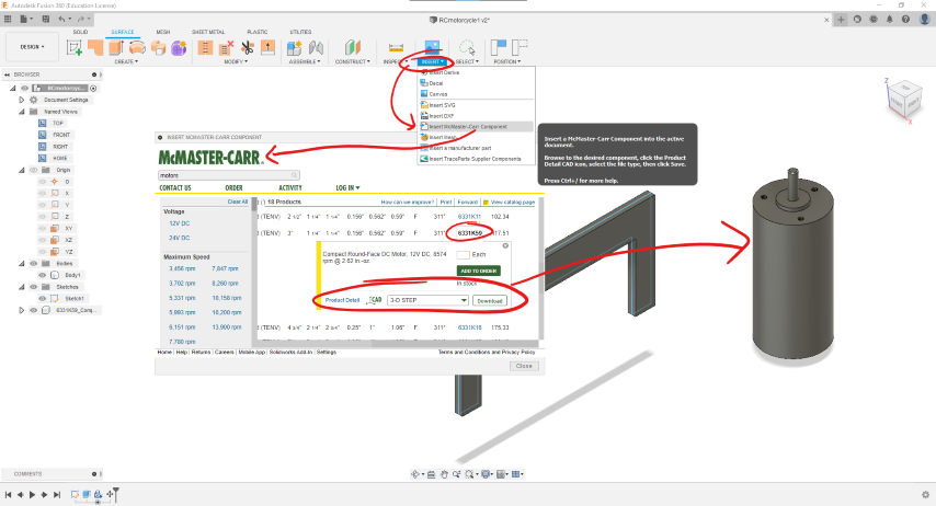
No idea of scale, let’s import a motor to contrast size. Fusion 360 has a really nice feature that lets you open a window to browse McMaster-Carr’s website and directly import a part’s CAD file into your project space, no need to deal with the hassle of any files! I found a similar DC motor to the ones in the Fab Lab inventory list and imported it from McMaster-Carr. Woops, looks like I need to make everything bigger to accommodate a bigger motor! Or find a smaller motor to work with that’s still in the inventory list.
Keep moving for now, worrry about scaling later. Some trouble getting sketches to extrude correctly…
Something weird happening when circle in sketch cuts through middle. The full fill is not being extruded. Couldn’t find a workaround quickly so changed to a triangle pointed shape to avoid any sketch lines “ruining” the fill for now.
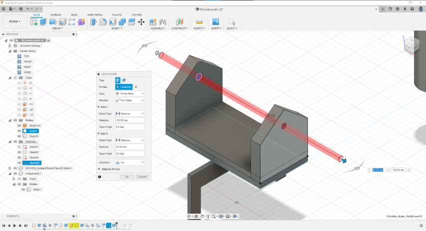
Drew a hole where the axle will go to hold up the gyro. Draw once, cut twice. Select “two-sided” direction to catch both ends. Make sure in “Objects To Cut” at the bottom of the menu, all relevant bodies are selected otherwise it will be ignored for the cut.
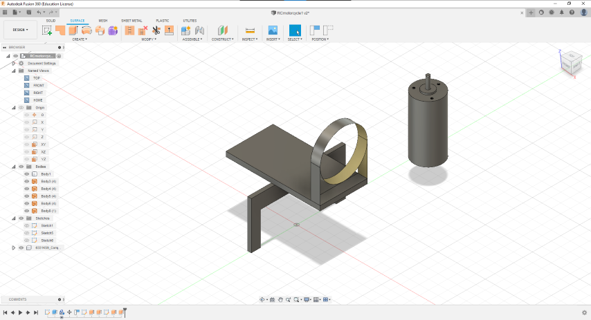
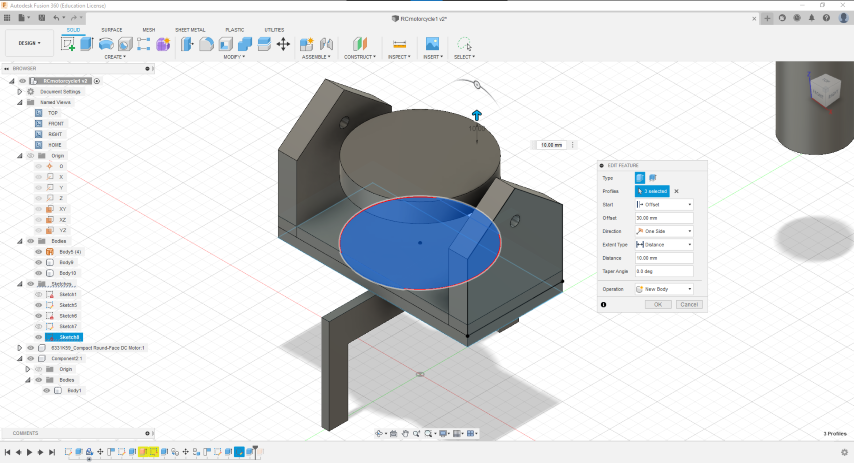
Next added a circle sketch on the base and extruded with an offset so it produces a flat cylinder representing the gyro, held mid-air.
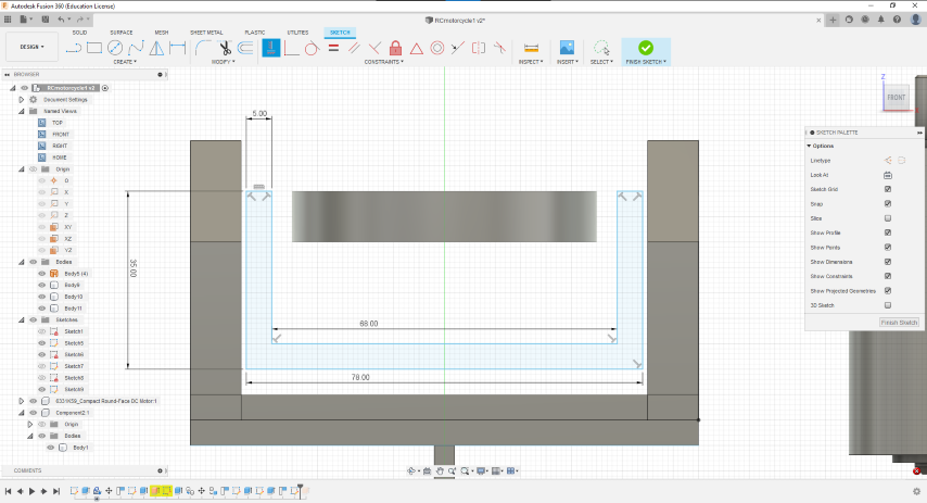
Sketch a gimbal to hold the gyro.
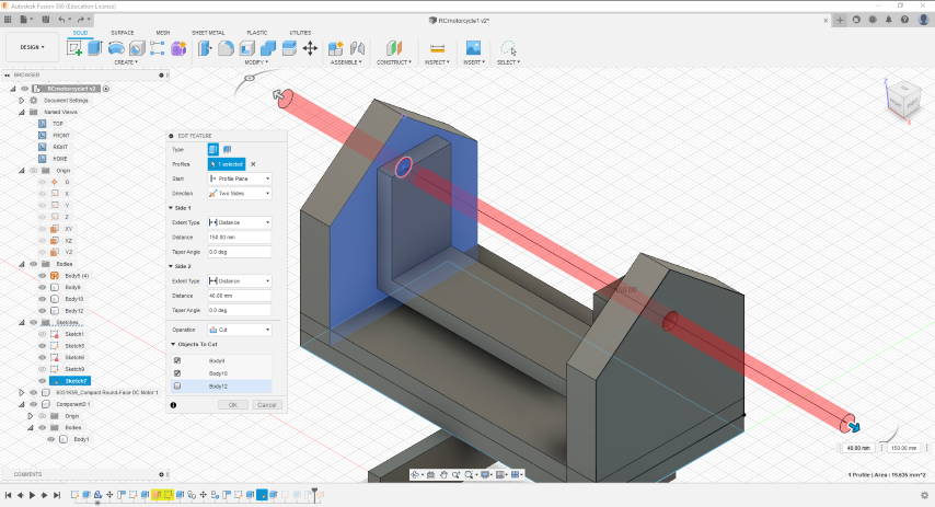
Oh no! I wanted the axle hole cut to go through the gimbal too. Well, since I drew the gimbal later, it is not a readily available object to be included in the previous cut. So, to solve this we “go back in time” by selecting the gimbal sketch and body in the Design History timeline at the bottom of the screen, and dragging it to before the axle hole cut was done. Now, when we go back to the “edit cut” of the axle hole extrude cut, “Body12” shows up as an option to cut. Check the box and now all 4 holes are cut by the same sketch!
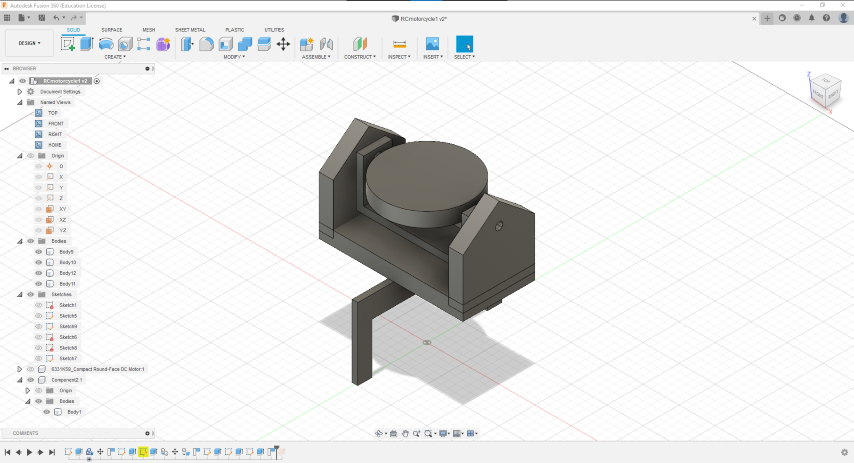
Semi-final assembly of Spiral 1.
Future work: - Add bearings from McMaster-Carr and axle shaft. - Add motor underneath gyro and attach to gimbal - Separate out gimbal and gyro as a component; simulate swinging motion
Additional Thoughts
- Solidworks is a bottoms-up approach
- Fusion 360 is a top-down approach
This leads to some rules to follow for Fusion 360:
Rule #1 - Always start a new file off with a NEW COMPONENT
Rule #2 - Rename all assets (components, sketches, bodies) right after you create them!
I did not follow these rules or know about them until reading about Fusion 360 after this first stab at using Fusion 360 to make my Spiral 1 gimbal design, which turned out quite messy in terms of design history and asset management.
Design Files
- Raster drawing of Gogoro rider assist gyro
- Vector drawing of GCMC motorcycle logo
- 3D model of final project Spiral 1