9. Molding and Casting
Taiwanese Chocolate Prototype Molds and Cast
Group assignment
- Review the safety data sheets for each of your molding and casting materials
- Make and compare test casts with each of them
- Extra credit: try other molding and casting processes
- Group Site Link
Individual assignment
- Design a 3D mold around the stock and tooling that you’ll be using, mill it (rough cut + (at least) three-axis finish cut), and use it to cast parts.
- extra credit: use more then two mold parts
Learning outcomes
- Design appropriate objects within the limitations of 3-axis machining
- Demonstrate workflows used in mold design, construction, and casting
Process of Molding and Casting
In this week’s assignment we will design a 3D object that we will then produce using a 3 step process going from positive mold -> negative mold -> positive cast.
First, using our CNC mill we will cut out the shape from a block of wax, this is our first positive mold. Using this we will then cast a negative mold using rubber silicone (Oomoo 25). Finally, using this we can cast a positive casting in resin or other material.
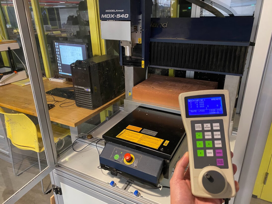
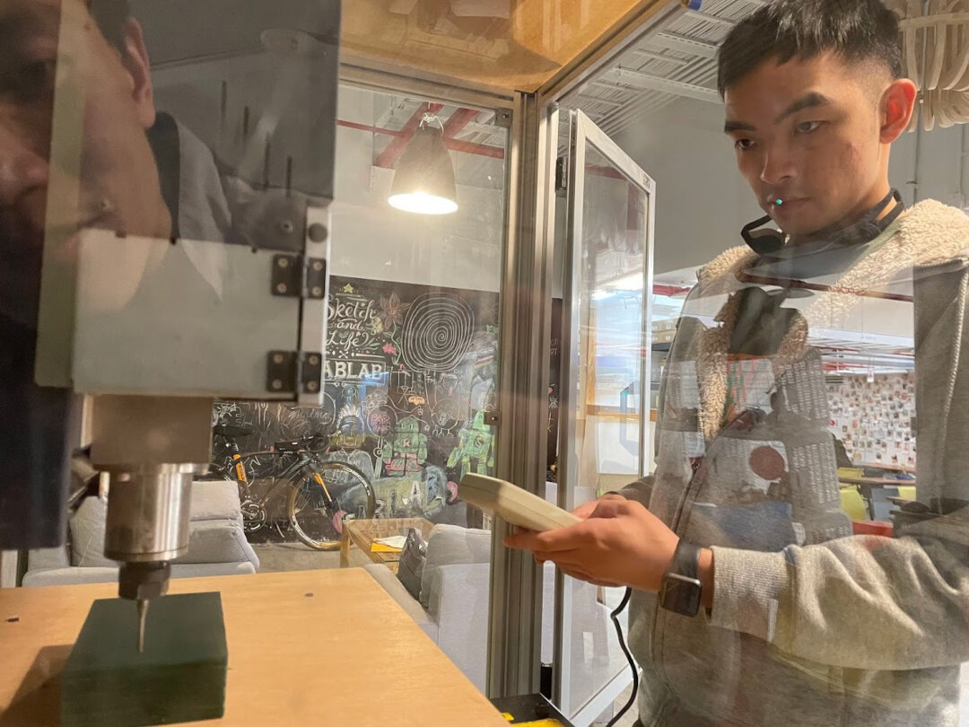
Machine Setup - Roland Modela MDX-540
Ted showed us different ways to operate the MDX-540 for this assignment. The lab computer connected to it has a few software programs we can use: SRP Player, Dr. Engraver, VPanel. We can also feed the computer NC G-code produced by another CAM such as Fusion 360.
The MDX-540 runs in either RML mode for NC mode. It has to be rebooted to switch between the two. RML mode is for Roland OEM software like SRP Player to take an STL file and make toolpaths and execute with. NC mode can take generic G-code from another CAM software, but it has to be in the format Roland accepts (Roland ISO in Fusion 360).
Fablab Taipei’s large format CNC mill - MDX-540
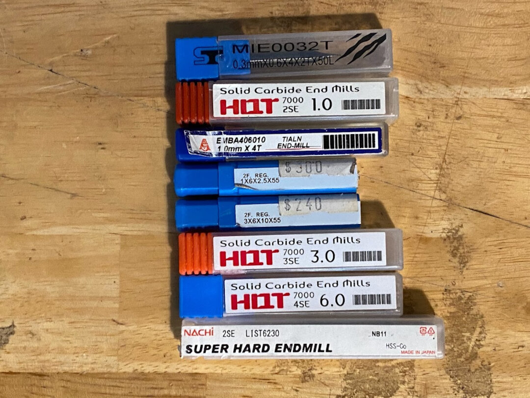
Assortment of collets and end mills available to use with MDX-540
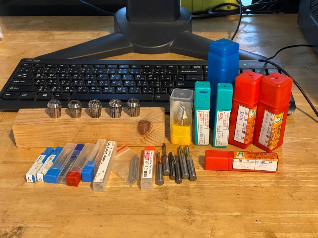
Since our molds will be small with detailed work, I narrowed down our end mill selection options to these smaller ones.
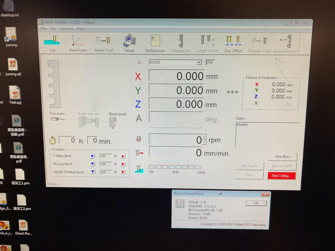
This is VPanel, the control panel software for the MDX-540. This is where to load custom G-code from an outside CAM if desired.
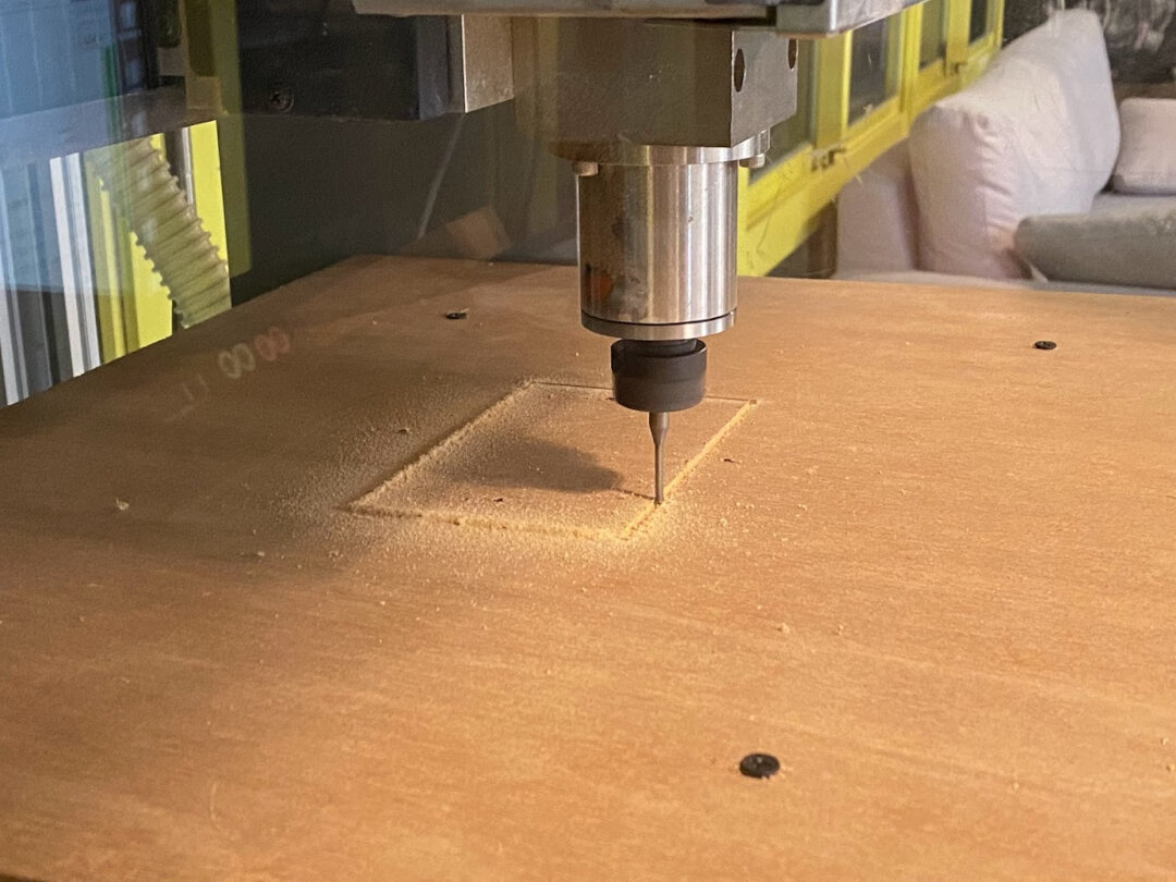
To cut out our wax molds, the machine needs to hold the modelling wax securely. We first measured the dimensions of the wax blocks we are using and then cut out a jig in a wood platform with an interferance fit to hold the wax block very tightly.
Zero the device and do air cuts to be sure before cutting.
Milling out the wood slot for the wax blocks.
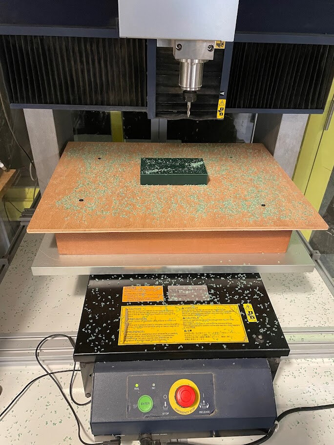
Face cut to flatten top surface of wax block in preperation for mold cutting.
Fusion 360 CAM
To better understand how we can set up our toolpaths in CAM for the best results I experimented with Fusion 360 as the CAM first. One of the things I wanted to learn this week was how to do 3-axis milling and specifically “ramping” to produce smooth curved surfaces with flat end mills.
Started by making a simple test shape like a hockey puck with an asymmetrical curve on top.
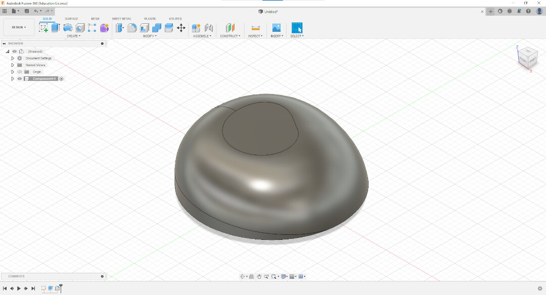
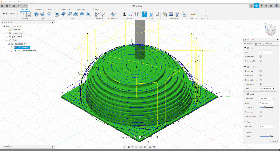
Tried out different 3D milling operations in different orders. 3D Adaptive Clearing was the most efficient for initial rough cuts.
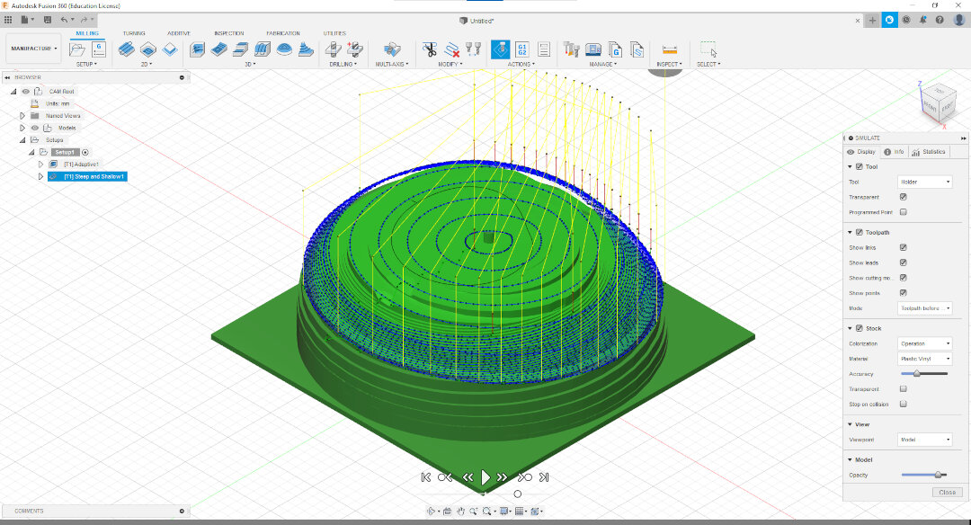
For finishing cuts on the curved surfaces, I found the Flow operation to be the best, especially set with a high number of passes. With Flow, the end mill will be moved in the u direction along the curve being cut (oh man I haven’t seen partial derivatives since college! Nerded out a bit that CAM/CNC can do this).
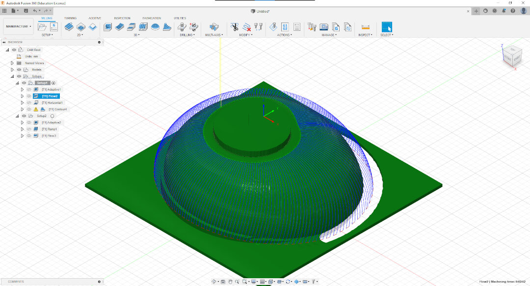
Outputed to NC code for a Roland ISO machine, tried it on the MDX-540 in NC mode, and got it to do a successful air cut!
So now I know after modelling my design in Fusion 360 I can confidently set up toolpaths in the Manufacturing workspace, then output it to G-code and it will run on our MDX-540.
Ideation
1-sided molds are the easiest. I have some friends making chocolate in Taiwan so this can be a relatively easy fun project to make chocolate shapes for Taiwanese chocolate. Can do fairly easily after my “real” assignment for the week.
I wanted to keep with the theme of motorcycles or dogs for a more challenging project, and perhaps try using Blender to create more artistic shapes more easily.
For 2-sided molds, there’s limitations of 3-axis milling, features like an exhaust pipe would not be possible to cast with the body since it has empty space behind it and the end mill would not be able to reach it without destroying other parts.
I’ve never used Blender before, and would really like to try, but tutorials made it seem like it would require a lot of upfront learning to get to a cool looking design I would be proud to machine a mold for and cast. So the search continues…
Alloy wheel
Browsing the internet for more ideas, I stumbled upon tutorials for designing alloy wheels in Fusion 360. Still related to vehicles which I like, and much more practical to learn quickly and stay in Fusion 360 for speed of getting to a manufacturable G-code this week.
Real life wheels have a lip around the circumference for the rubber tires to sit on. Thus, alloy wheels produced in factories actually use 6-sided molds! (Top, bottom, 4 around sides).
I could simplify to a 4-sided mold (2 molds around sides cover 180deg each instead of 4 molds x 90deg like in real wolrd manufacturing process)
Could simplify further to 2-side mold and just ignore the wheel rim profiles, but the end result would not look as realistic and it wouldn’t hold an actual tire well. Plus, Neil challenged us to create molds with more sides as a practice in 3 dimensional thinking and deepening our knowledge of molding and casting!
The final result can be used in a real RC toy! With the addition of another mold making the rubber tire, or buying commercially available ones from RC hobby shops. Since this component is a critical force-bearing load, a solid casted alloy wheel will be for sure stronger than if the same design were just 3D printed in layers.
Since I’m thinking of making an analog clock for my final project now, with many gears inside, this would still also be good practice for designing cool shapes inside a circle or gear. Since CNC doesn’t care when it comes to the actual pattern of supports inside, it can be as intricate as an artist would like!
Design
Alloy wheel
Alloy wheels are different for motorcycle and cars.
For cars, all 4 wheels are the same, and are at the outter edges of the vehicle, so there is an outward facing side. This also means they have a asymmetrical bending load from the wheel axles, which may be the reason their alloy wheels are not designed to be symmetrical down the middle of the wheel.
Car Alloy Wheel Offsets Explained
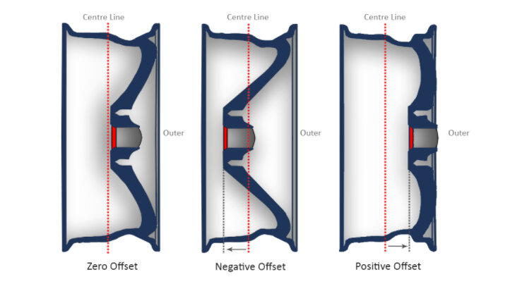
Credit: PerformanceAlloys
In contrast, motorcycle wheels are different for the front and back, and are in a line directly over the center of mass of the vehicle. Thus, alloy wheels for motorcycles tend to be very symmetrical down the middle of the wheel.
Motorcycle front wheels tend to be bigger diameter and skinnier for better steering and manueuverability; rear wheels tend to be smaller diameter and wider for better traction and load carrying capacity.
For this assignment I chose to go with a motorcycle rear wheel.
OEM rear tire size for a Ducati Panigale V4:
200/60-ZR17
You can understand how to read tire codes here but basically the dimensions we need for the wheel are:
Width = 200mm
Diameter = 17in (431.8mm)
I will scale it down to a diameter of 30mm for the mold but keep all proportions accurate. I will also use parametric modeling in Fusion 360 so if I get the chance to make a full-size version in the future I can scale up the design easily!
I would also like to make the wheel rim profile accurate to real world designs as well and found there’s a general shape to follow for flanges. This design keeps the rubber tire seated securely on the wheel.
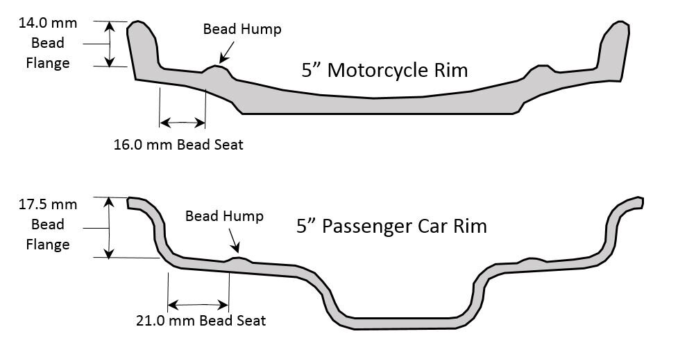 Credit: Iron Butt Association
And then there’s the question of whether flanges are included in wheel dimension measurements. They’re not.
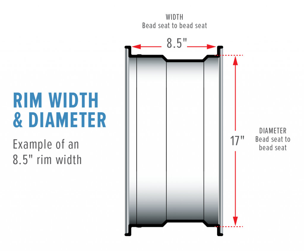 Credit: Santa Ana Wheel
OKAY I’m probably getting way too nitpicky now in terms of moving fast for Fab Academy, but well, I’m a gearhead so I enjoyed doing this research anyways, and if I ever do machine/mold this alloy wheel in life-size, I’d rather do this research once and get it right the first time.
Now all the basic design parameters are known, let’s get to CAD already!
First I set up some parameters to aid in the modelling.
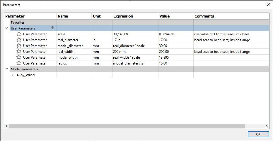
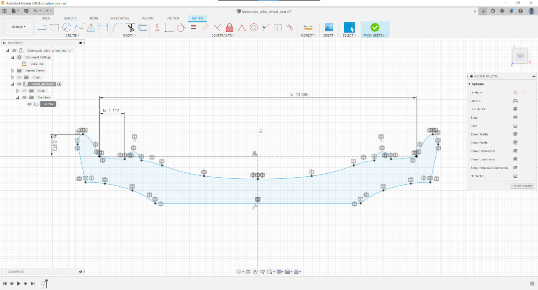
Then use splines to create profile of rim.
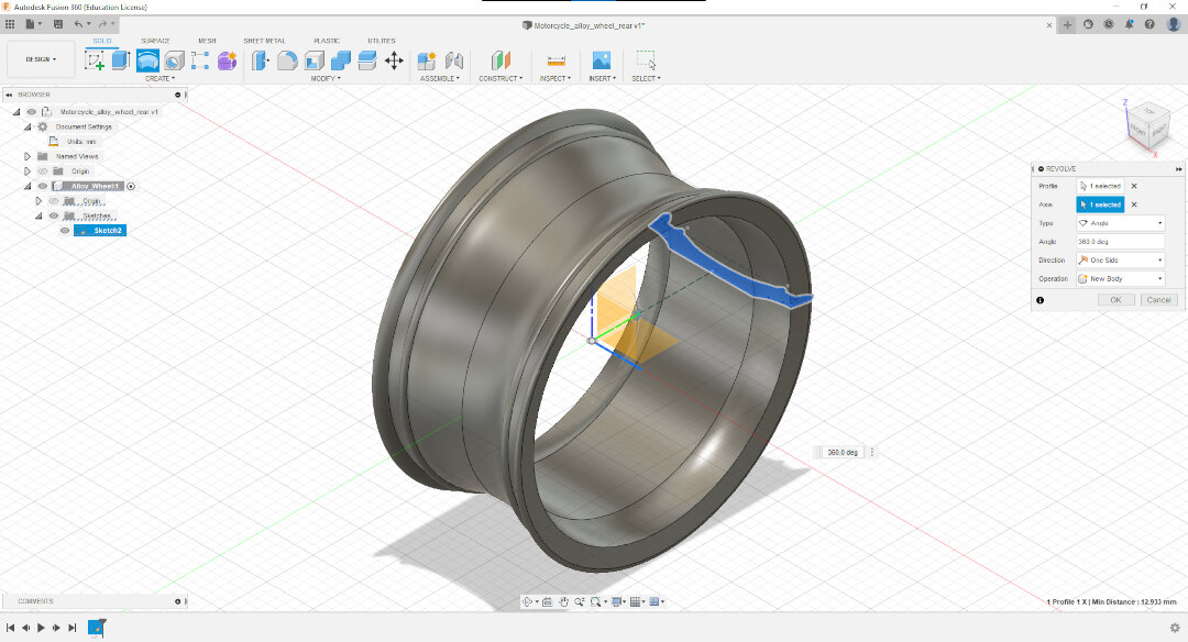
Revolve 360deg.
Check parametric design. Crap I forgot splines don’t scale properly in Fusion 360… Changing to full-size dimensions just messes everything up. Well, too late now to worry about that, keep moving…
Potential issue with wall thickness noted, it’s only ~1mm at this scale, afraid it might not be enough gap for resin to flow through well if it’s viscous. And we don’t have a vacuum pump at this lab to aid. Perhaps this can be mitigated by a pouring strategy?
Could make walls thicker, but decided to keep going as a test of limitations of molding and casting for fine objects. Machine time is expensive, but I’ll redo it if I have to. We have recycled wax blocks I could use for a second try.
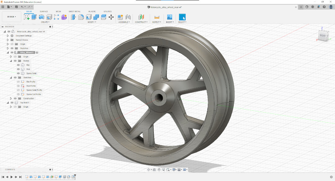
Final design!
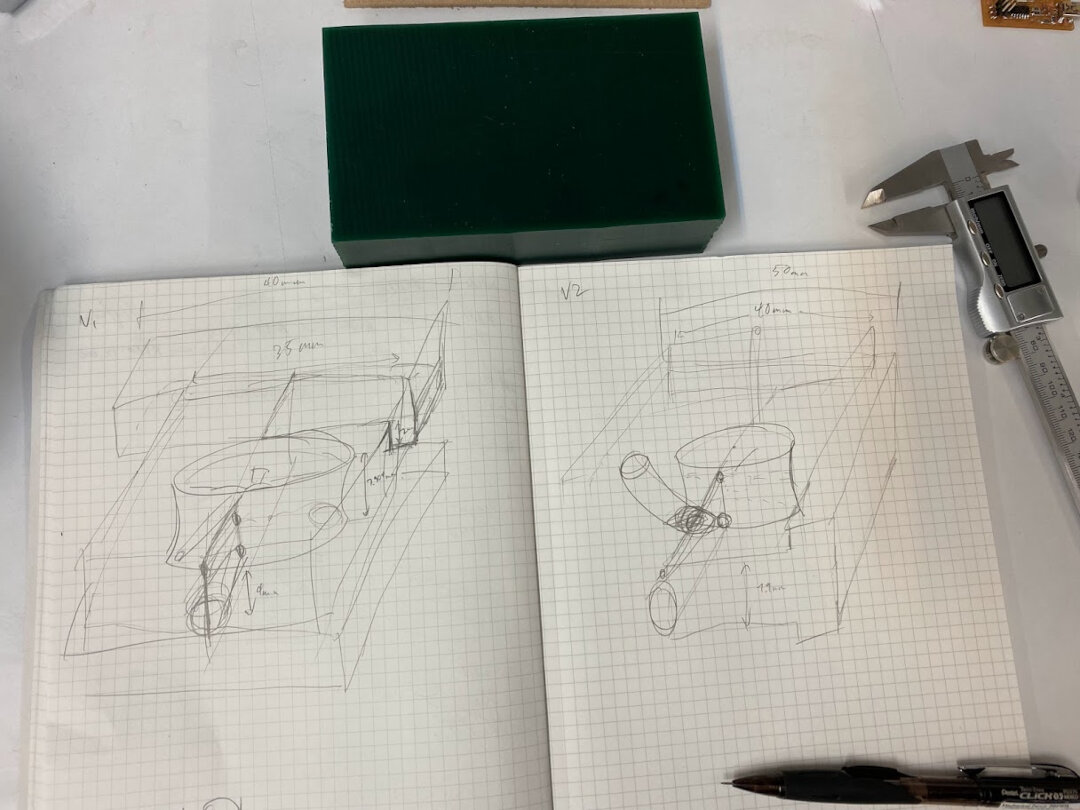
Banging my head against the wall for hours figuring out how to fit 4 pieces of the mold together, while having space for a sprue and air vent hole, and reasonable sized for a 30mm diameter…
Taiwan Chocolate
At this point I had already spent too much time trying to figure out the alloy wheel 4-piece mold setup AND the CAM operations to make it work. Decided to avoid sunk cost fallacy and move on to a more realistic Spiral 1 project I could finish for the week’s assignment.
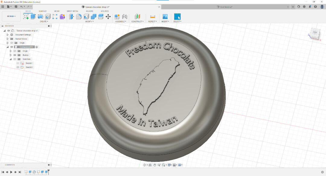
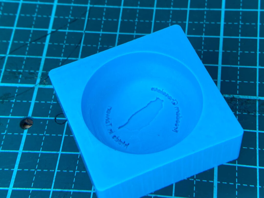
Designed a chocolate mold for Taiwanese chocolate. Working project name: Freedom Chocolate. This took a nontrivial amount of time by itself. The fillet curves around the top are asymmetric on purpose to give it a more organic feeling.
Fusion 360 Manufacturing Workspace attempt
First step, set up cutting operations with Fusion 360 CAM (“Manufacturing” workspace)! Used lessons learned from the test mold to do Flow cuts for the curves.
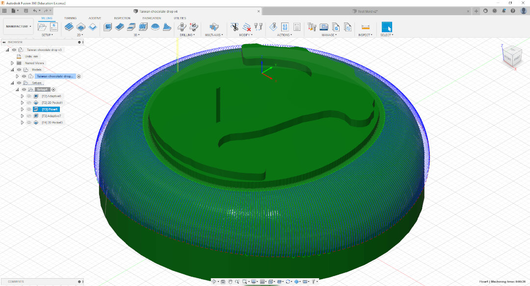
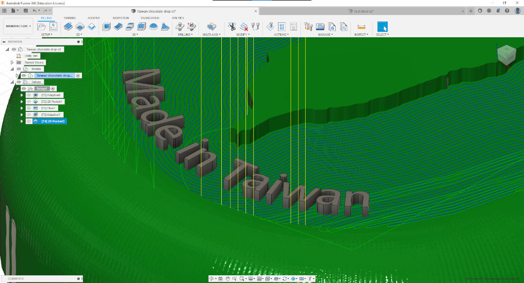
The text on the top were really small and I struggled for a few hours trying to set up cuts that would work with them. In the end the best operation set up got the Taiwan map cut out well, but would just mill over the text… no good.
SRP Player
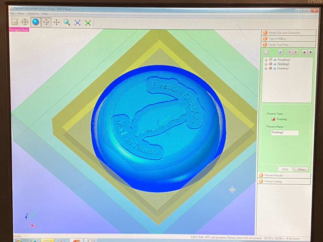
Another time-saving move to just get a Spiral 1 project done for the week. Ditched Fusion 360 CAM and just exported the STL to use with Roland’s OEM software, SRP Player. The options were far more limited than Fusion 360 but still produced okay results. It’s the tradeoff for ease of use I guess. E.g. SRP Player cannot do flow cuts. At best Parallel cuts that leave rough lines on curved surfaces if the stepover size is too large.
Set up one roughing toolpath with a 3mm flat end mill, a finishing toolpath with the same 3mm end mill, and another finishing toolpath with a 0.3mm flat end mill. Last finishing toolpath was limited to the z-height of the top surface, so that toolpath was primarily working on the detailing of the Taiwan map outline and the small text.
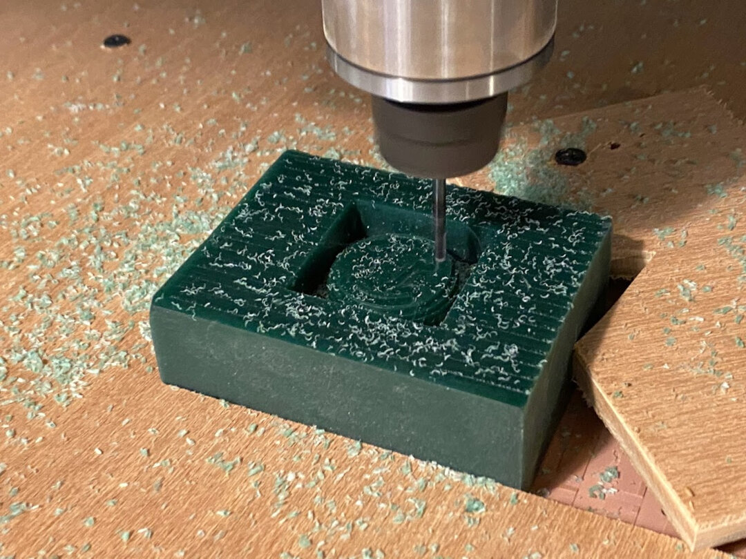
Machining the positive mold
The first 2 toolpaths used a 3mm solid carbide flat endmill with 8mm flute and straight shoulder. This was the only end mill with a long enough flute and shoulder that we had that could reach the bottom of the chocolate shape without hitting the side walls. The other end mills we had were all small, with shoulder lengths less than a centimeter long and leading into a sharp V shaped shoulder right away.
My classmate Hanson who finished his design first had started milling and ran into this problem. So, learning from this lesson, I decided to stick with the 3mm straight end mill for first rough cut and first finishing cut.
After first roughing toolpath.
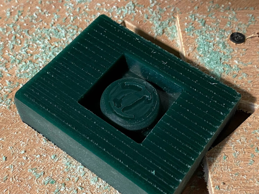
After second toolpath, the first finishing cut. Shape mostly formed, just detail left on top.
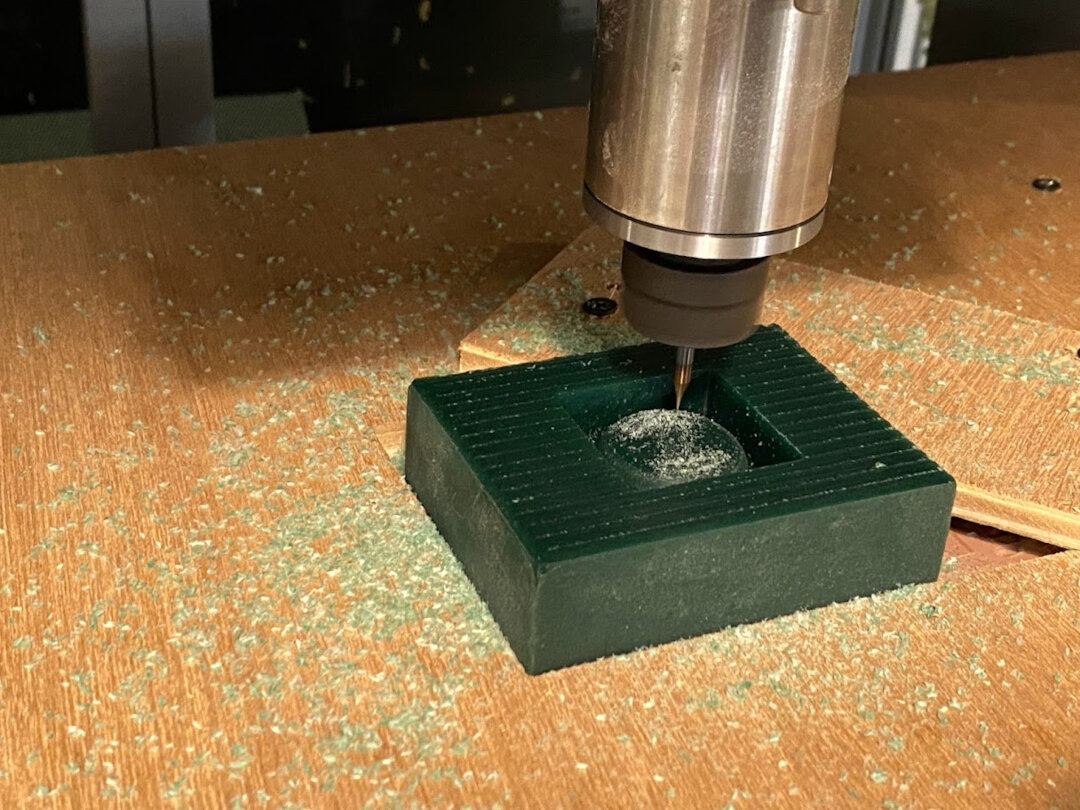
Final toolpath with 0.3mm end mill took the longest, 65min.
The result was not bad! Although some text details were too small like the middle holes of “e” and were not able to be cut out.
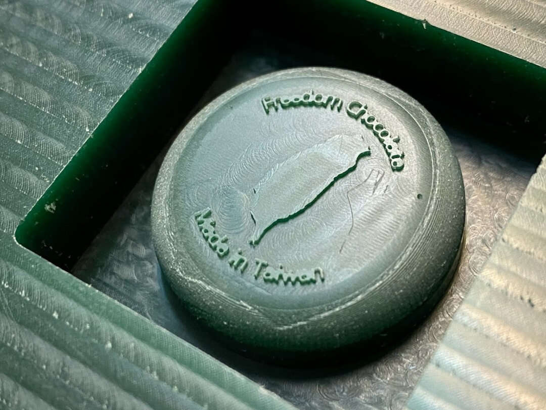
Shortly after this picture I was trying to clean some wax chips out of the bottom of the mold with a paper towel and hit the top accidentally. Some letter details fell off right away like the bottom of the T in Taiwan… sad.
Have to be more careful in the future and also make font bigger and thicker. Or just use an engraver end mill to do the text in negative.
Material Safety Data Sheet (MSDS)
Before casting the negative molds with Oomoo and the final positive molds with resin, we read the MSDS for both and noted the hazards and safety recommendations. We prepared gloves, safety glasses, and moved a table outdoors to do the process with good ventilation.
Making negative molds
Chocolate mold for Taiwan chocolate made with Oomoo 25. There were some defects in the text. Font too small. Everything else looked good though, curves were smooth and Taiwan map outline was perfect!
3D prints
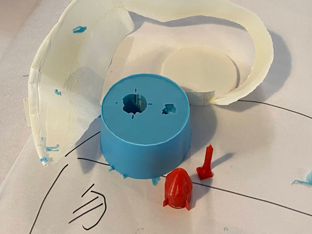
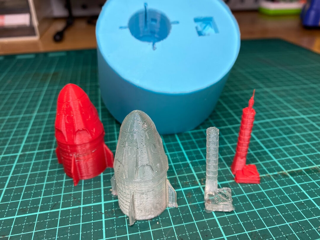
As a fun additional test, I 3D printed a couple objects to try and replicate using molding and casting. Limited them to 50mm height so they’d fit in the cup. Objects: SpaceX Crew Dragon and Taipei 101
It was hard to get the dried Oomoo out, so had to rip open the paper cup.
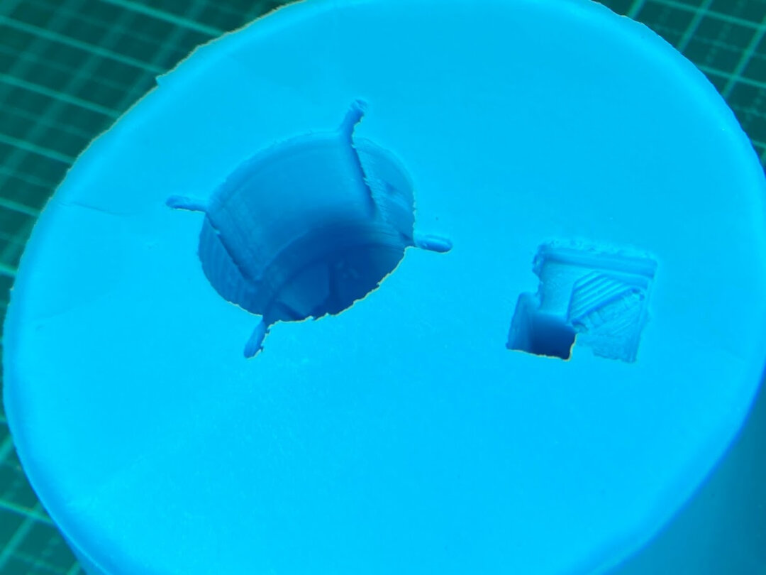
You can see the fine details impressed in the Oomoo. The limitation of this method is the resolution of the 3D printer, not the molding and casting process!
FabISP
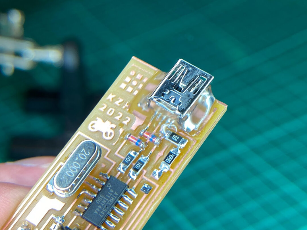
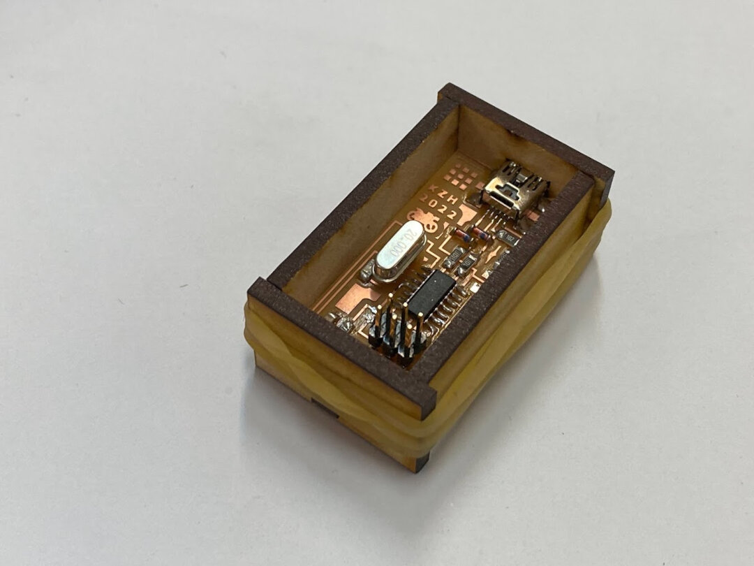
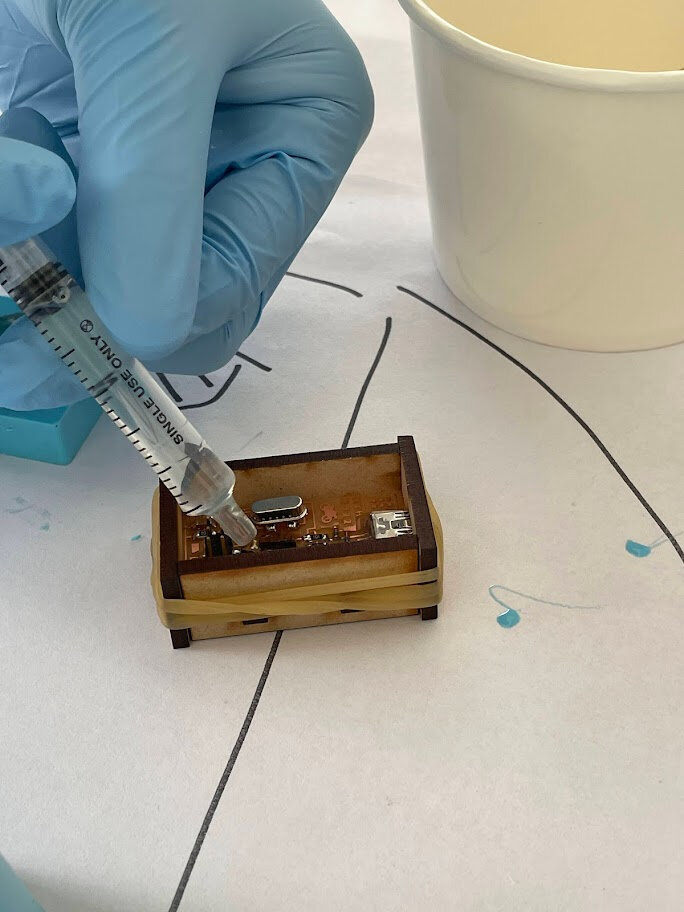
I wanted to protect my finally functioning FabISP so I made a laser cut mold for it to also cast a layer of resin on top of it.
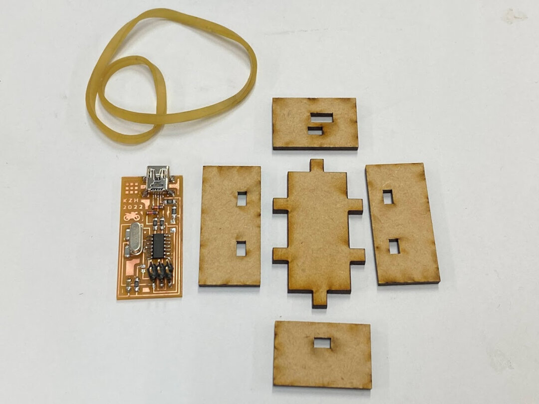
To prevent resin seeping into the more delicate USB socket, I first hot glued around it to seal it off. Followed with a quick blow of the hot air gun to let it seep into the crevices for sure. Clear tape added on top of the socket to cover those holes in case.
Assembled and ready to cast! No more accidental crystal bending or trace scraping!
Casting
Moved table outside for casting so there’s plenty of ventilation.
To “activate the resin” add some hardener fluid and mix. Pot time is ~10 min, meaning you have to fill everything before then! In practice, we noticed it started to thicken even before 10 min. (perhaps we used too much hardener)
Ratio ~1-2g hardener to 200g resin
(Hard to be more exact with our 1g accuracy scale)
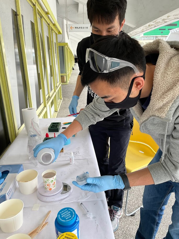
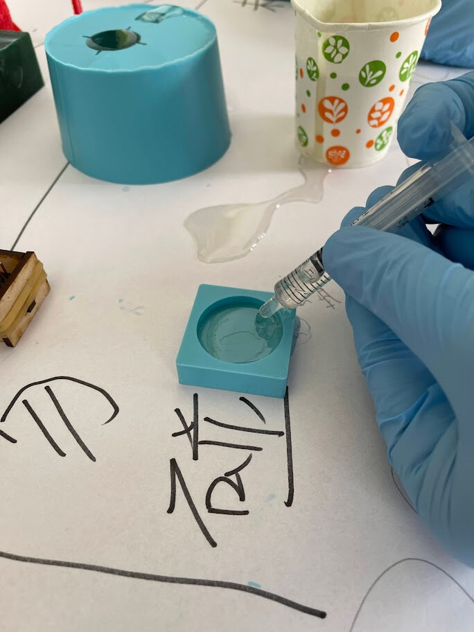
Used a syringe for better control of amount of resin used.
Demolding
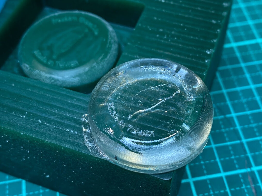
Resin cure time stated 75 min, but it was humid out so we gave it a bit more time. Here’s the final reveal!
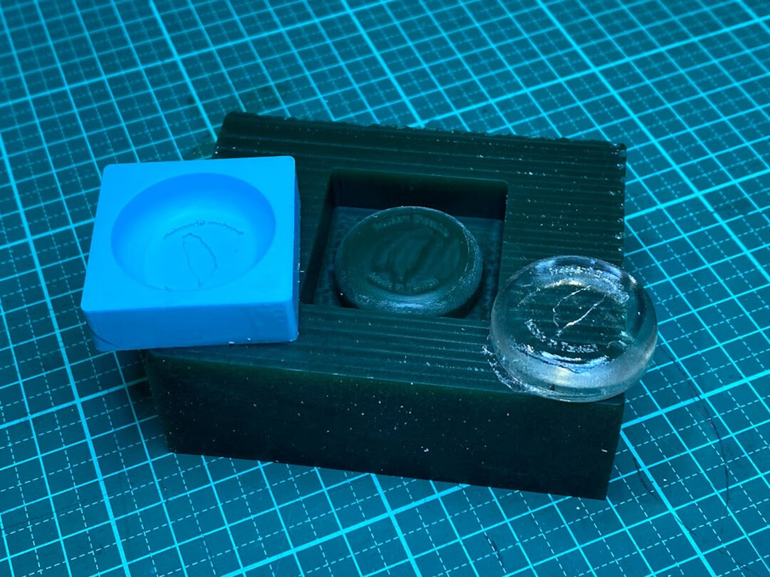
Taiwan Chocolate final molds and cast all together
3D printed objects molds and casts. SpaceX Dragon capsule came out well, Taipei 101 not so much. Resin couldn’t get down all the way to tip of the tower. Also it was very difficult to demold and the tower snapped off the base when trying to remove it. A 2-sided mold would work better for the Taipei 101 replication.
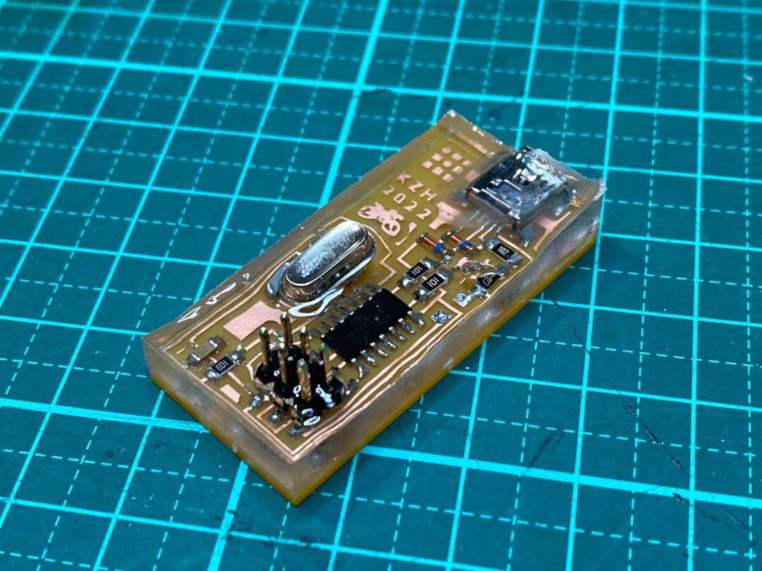
FabISP final cast. Did some additional post-processing by using a utility knife to cut the raised edges down a bit (chamfer). Saw some youtube videos about using a hot air gun to make the surfaces smooth and clear and remove bubbles, tried it but it didn’t really help. Perhaps our resin is different or wasn’t dry enough yet. So this final pic is pretty much as good as it looks!
Conclusion
Learned a lot about the molding and casting process this week as well as 3-axis machining. Definitely a ton of cool stuff can be made just using this week’s tools!
Why not just 3D print?
The nozzle of an FDM 3D printer is typically 0.4mm diameter. This means the smallest detail a 3D printer can hypothetically achieve is 0.4mm, but it’s actually more because a single thread of plastic from an FDM 3D printer is not very strong by itself so it needs support from surrounding geometries.
In contrast, the smallest end mill we have available in the lab has a blade diameter of 0.3mm. But the details it can produce can go even smaller. As we saw in Week 4 when we tested the thinnest circuit board traces we could mill out, a 1/64” end mill (~0.4mm) can cut a trace as thin as 6 mils (0.15 mm). This is because a positive shape is not limited to the width of the end mill as the CNC can cut it’s outside on both sides. Negative shapes are limited though, as can be seen in the Taiwan Chocolate mold’s text. Some “e” letters had the middle hole missing because they were smaller than the 0.3mm end mill.
Additionally, with “ramping” an end mill can move in 3 dimensions at once and carve out curved surfaces very smoothly. Depending on how far apart each pass of the end mill is (“stepover”), very very smooth detail can be achieved.
Of course, SLA 3D printers can achieve a higher resolution than FDM and perhaps it’s sufficient for a project. Setting up the CAM for machining out parts and then doing the machining can take a long time depending on the complexity of the design (as I learned the hard way this week with the alloy wheel struggles), and then more time for molding and casting and waiting for resin to dry. So depending on the project needs, perhaps a good balance between high quality (3-axis milling + molding and casting) and high speed (FDM 3D printing) is SLA 3D printing.
Lessons learned
I like to give myself extra challenges beyond the bare minimum to accomplish weekly Fab Academy assignments, because this time is invaluable and I want to maximize my learning. But also in Fab Academy we’re supposed to grow from where we’re at. This week I overexerted myself in the beginning of the week on a project scope that was too big and spent too much time struggling on CAD (4-piece mold of an alloy wheel) without getting to the main learning this week: 3-axis milling and molding and casting.
I was jumping into a Spiral 3 project right away, when I’ve never even done a 1-piece mold before. There was a mental constraint that we only had 1 block of wax, so first shot had to be perfect. In reality, we also had some recycled wax blocks we could use and if necessary could just buy more wax blocks from the store for about $15 USD each. Machining time is expensive, but being too perfectionist on CAD modeling is also time expensive in terms of not getting to the start of the milling process. In supply-side time management it’s always a balance between quality, efficiency, and practicality.
I also noticed I referenced documentation of previous students that I admired maybe too much, and was always trying to “one up” work that was previously done. But I shouldn’t compare myself with others, especially if they perhaps have more background experience in a certain area i.e. creating awesome math shapes with scripting. I could focus more on where I’m at, and improving myself from there. There are lots of basics to master in Fusion 360 that could make a lot of cool things, before getting into scripting!
Things I want to try with more time
- Fusion 360 sculpting (Forms)
- Blender sculpting - make a dog, futuristic motorcycle/car
- Molds with 2+ sides
- Machining aluminum
- Try modsproject CAM
Useful links
- How It’s Made - Alloy Wheels
- Smooth-On Oomoo 25 MSDS
- Resin MSDS - Styrene CAS 100-42-5
- Fab Speeds and Feeds calculator