14. Networking and communications
This week I worked on Network and communication assignment which was to design, build, and connect wired or wireless node or nodes with network or bus address.
Research
Inorder to connect two or more devices togather you need protocols so that your devices can communicate. And Network protocol are defined as set of rules that determine how data is transmitted between different devices in the same network.
I have learnt different types of communication:
I2C: which stands for Inter Integrated Circuit. I2C requires only two wires connecting all peripherals to microcontroller; Those wires are SDA(Serial Data Line) andSCL(Serial Clock Line) to carry information between devices.
I2C is a Master to Slave communication protocol; Each Slave has a unique address; Master device sends the address of the target slave device.
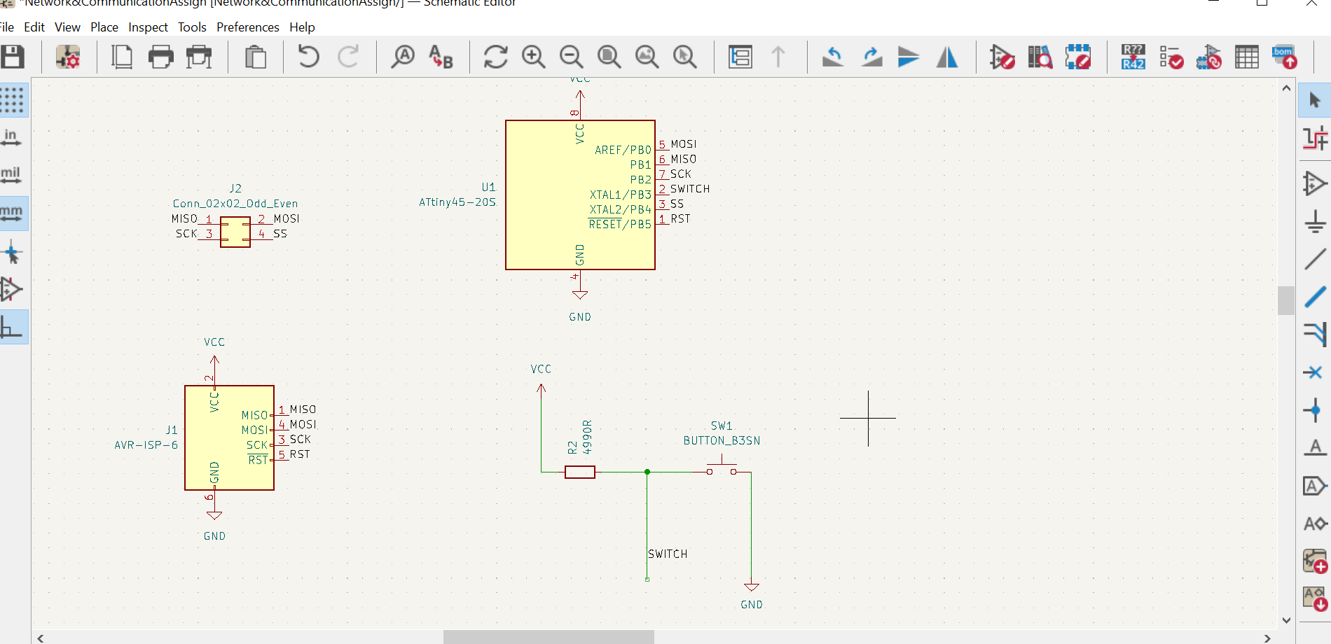
For my assignment, I need to establish a wired communication network between my two boards(Master with a switch on it and Slave board with a LED on it).
Master board which will have a switch when it is pressed it will lighten the LED on my Slave board.
Master board design
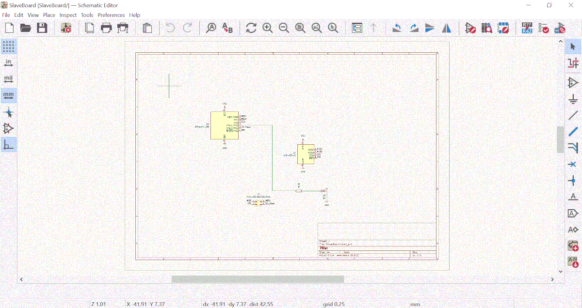
Below is the schematic of my Master board
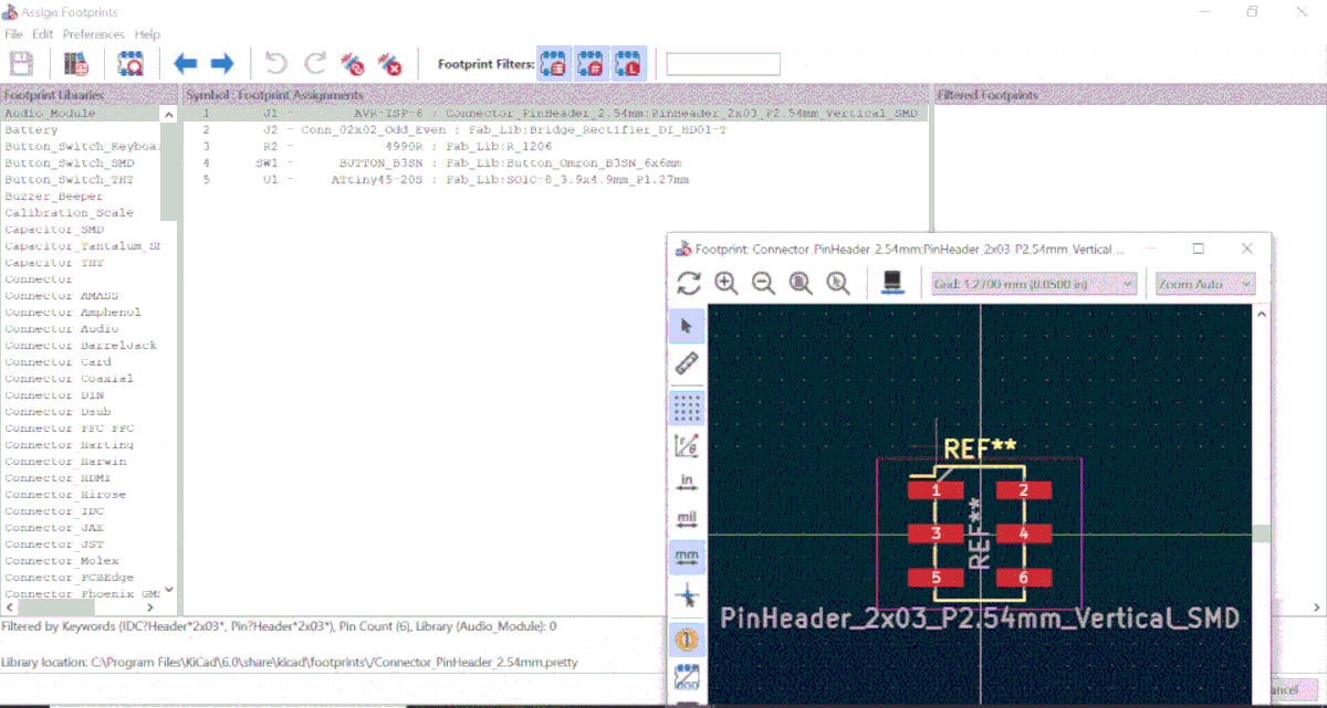
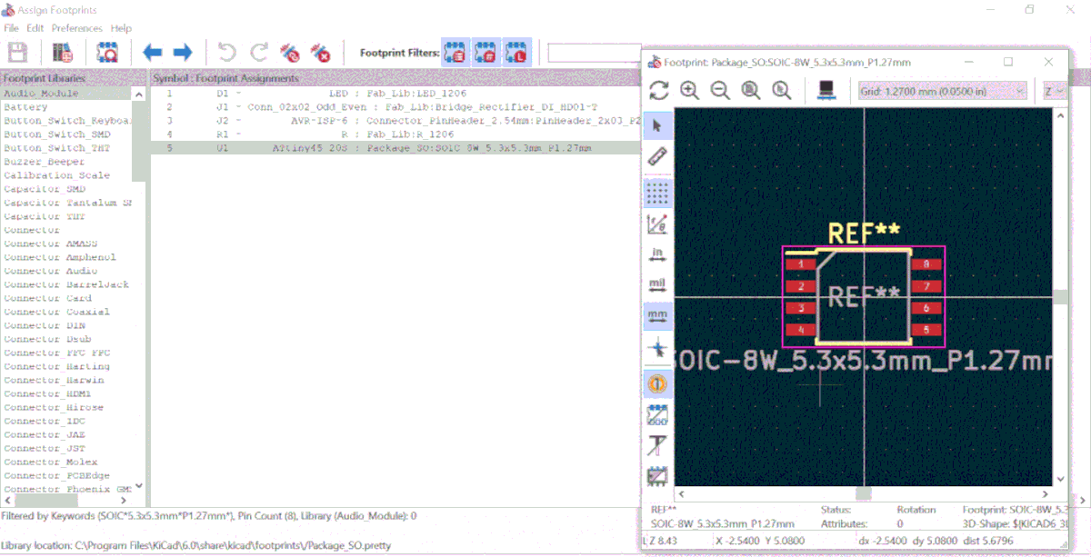
Below, are footprints assigned to my Master PCB
Below, is my Master PCB traces with its Edge Cut read to be plotted and putted in Gimp to produce PNG files to be putted in mods.

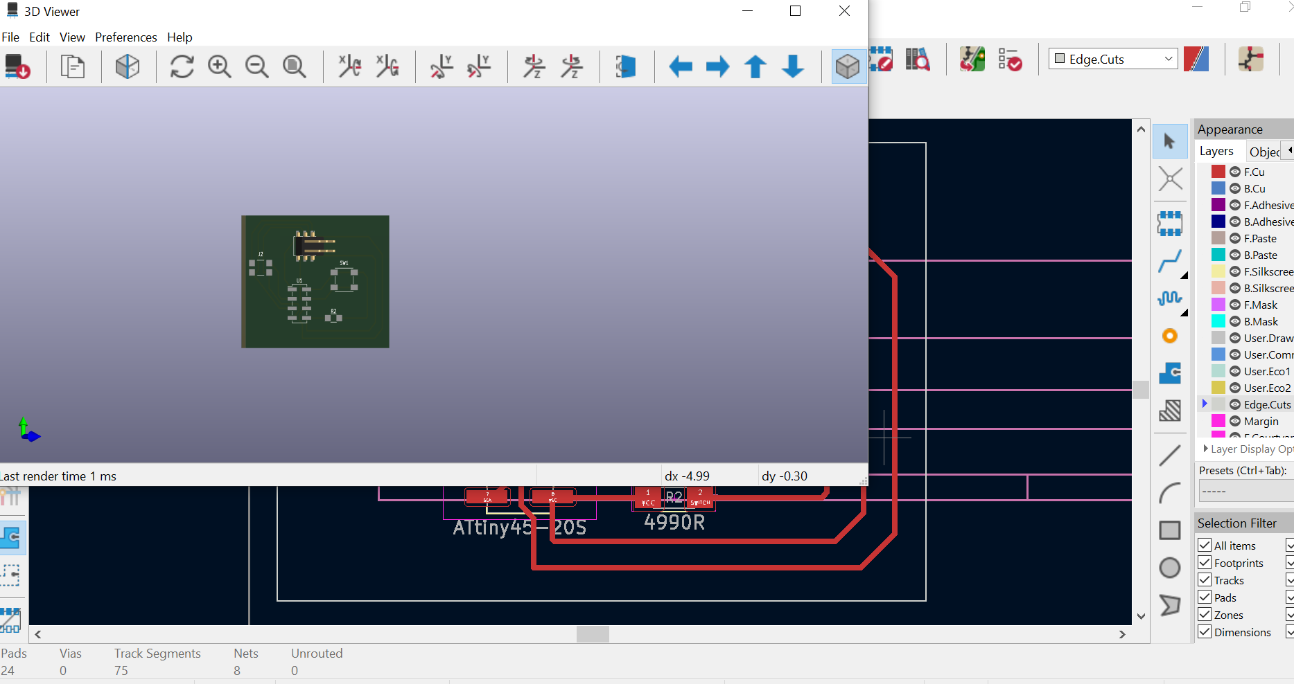
Below is the 3D Viewer of my Master PCB
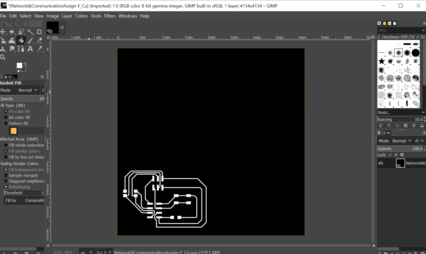
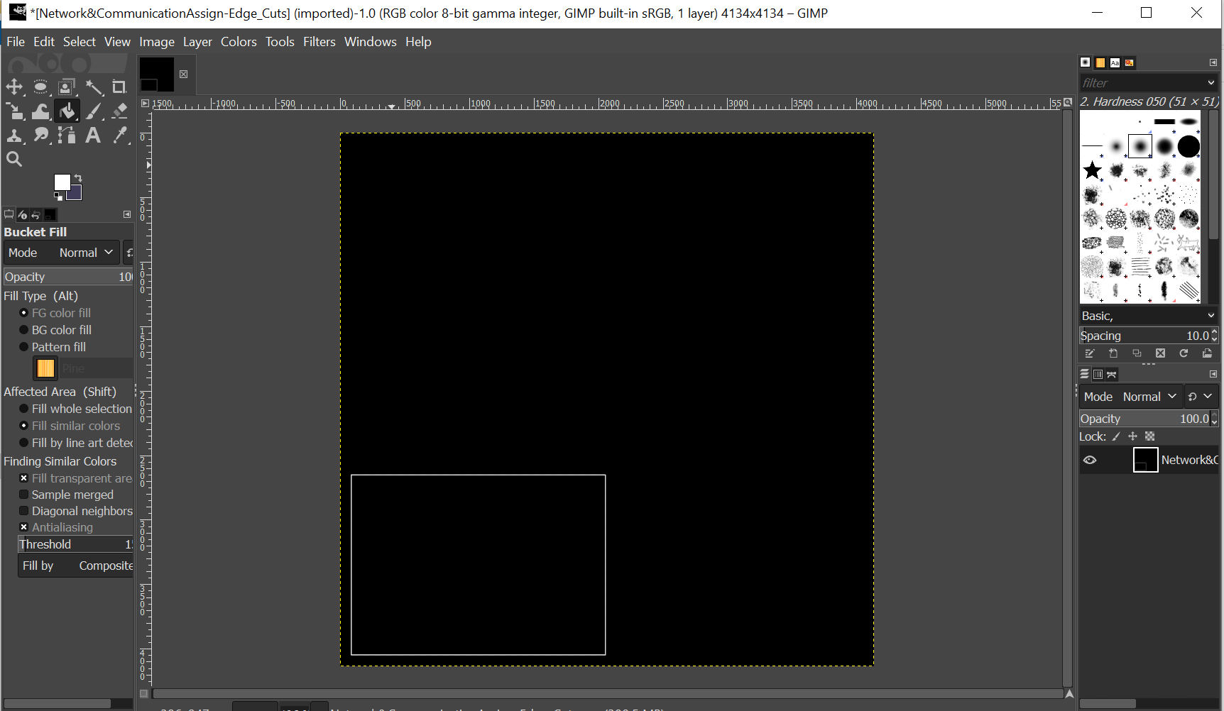
Below is how my Master PCB look like in Gimp which was putted in mods to produce F.Cu RML file.
Below is the EdgeCut of my Master Board in Gimp which will be putted in mods to produce RML file.
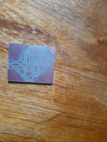
After producing F.Cu and EdgeCuts RML files, with the help of Roland milling machine I produced my Master board PCB below. As you can see I use a laser to remove short circuits on my Board and I soldered it using ATtiny 45, AVR-IS-6, 1 Switch, 1Connector, 1 Resister in order to get my final Master board.
Master board produced
After following steps of producing electronics, below is the produced Master board
After soldering my Master board, I program it in arduino to act as a master using its switch to lighten the LED on slave board. Using ISP programer, I loaded in master board the code below.
Master board programming
Below are arduino codes that I have used to program my board, you can copy them and reuse them too.
#includeSoftwareSerial mySerial(0,1); int Button = 3; void setup() { mySerial.begin(9600); pinMode(Button, INPUT); } void loop() { if(digitalRead(Button)==1) { mySerial.write("Blink"); } }
Slave board which has LED to be controlled by the switch on master board.
Below, I was adding my electronic devices
Assigning footprints according to what electronic devices we have in our local fablab.
I gererated a PCB, Rearange and routing it. I have also added edgecuts and adjust paper settings to plot my PCB and generate two SVGs files.
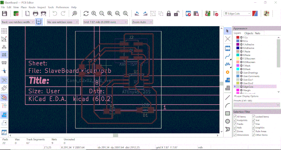
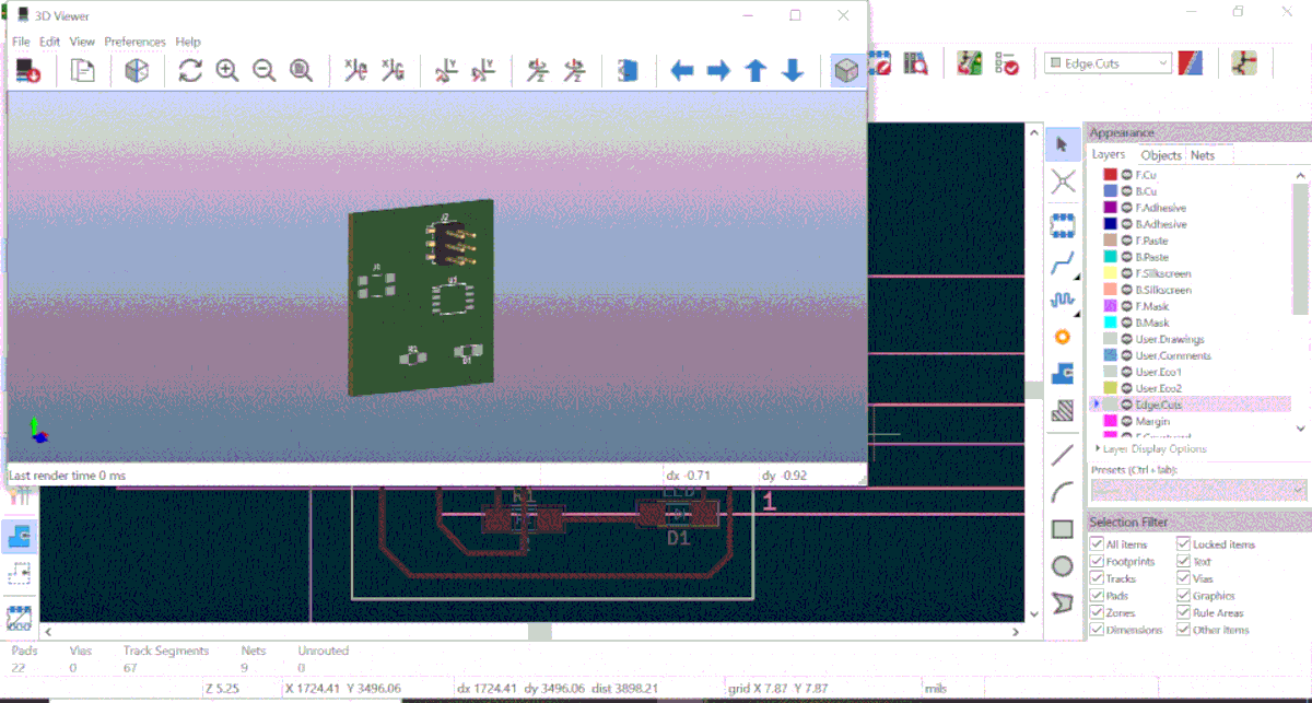
Below, is the PCB that will be produced 3D View.
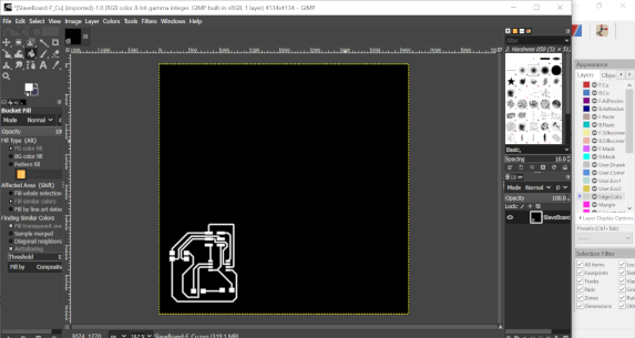
I opened my F.Cu svg file to produce the below PNG files to pe putted in mods for RML F.Cu file to be milled by our SRM 20 Roland machine.
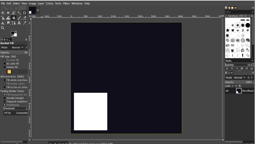
I did the same to produce Below EgdeCuts PNG file ready to be putted in mods.
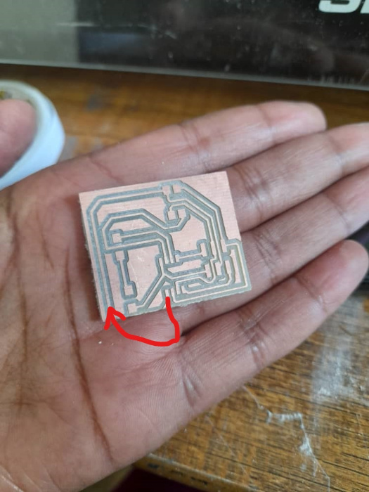
After F.Cu tracers, during the EdgeCuts I did a mistake of not set the X and Y of Roland to start at its orgine and I setted them manualy and one of my PCB route was cutted and I have used a Jumber to solve this for the ressource management purpose as you can see below indicated by the red line.
After soldering my slave board, I have programed it as you can see below

Below, are arduino codes I have used to program my board.
##**Slave board programming** #includeSoftwareSerial mySerial(0,1); int LEDpin =3; int incomingByte; void setup() { mySerial.begin(9600); pinMode(LEDpin, OUTPUT); } void loop() { if(mySerial.available() > 0) { incomingByte = mySerial.read(); if(incomingByte == "Blink") { digitalWrite(LEDpin, HIGH); delay(1000); } else { digitalWrite(LEDpin, LOW); } } }
Hello shot
Below, I have connected my Master and Slave board to communicate, At the connecting time I found that my Slave board is not powered, to correct this issue I have used electric jumpers(Yellowand Red jumpers are for power and others are for board communication)from Master board to it as below and works.
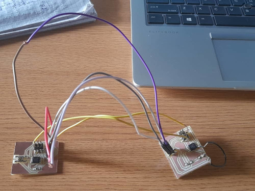
Below, is my HeroShot video
Used Files Here