12. Output devices
This week I worked on output devices; the assignment was to add an output device to a microcontroller board that I have designed and program it to do something.
Output devices in electronic systems
To carry out my assignment first, I have to know what are output devices in electronic systems and I found that output devices in electronic systems are devices that transfer energy from the electronical energy that has been processed to an other kind of energy such as light, sound, or movement.
For my work, I want to use a device which turn electronic system into light energy. And I choose LED as my output device.
PCB design
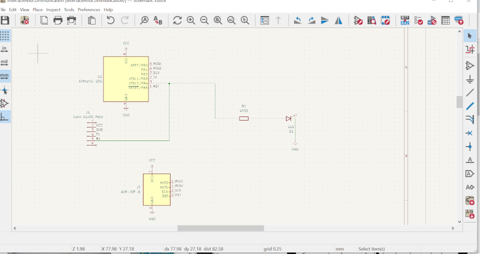
Using KiCad software, I designed a board which has LED as output device and below is the schematic design of my board.
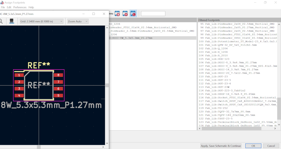
Below, I was assignning footprints to my electronic devices according to what we have in our fablab by double clicking on the choosen. And I clicked on Apply, Save Schematic & Continue then Ok.
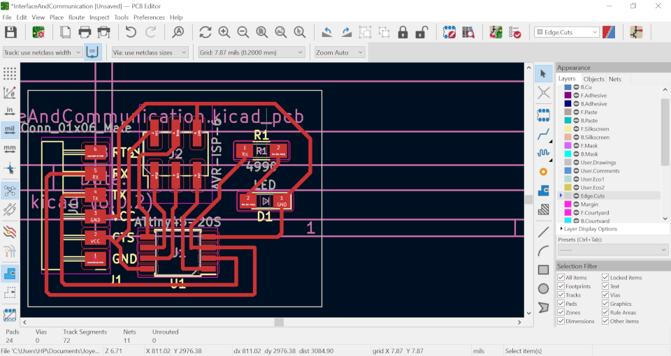
I have Updated my PCB from Schematic and rearange devices, routed them accordingly, add EdgeCuts, I also customized the paper settings by setting Height and Width to 4134 and produce a needed PCB.
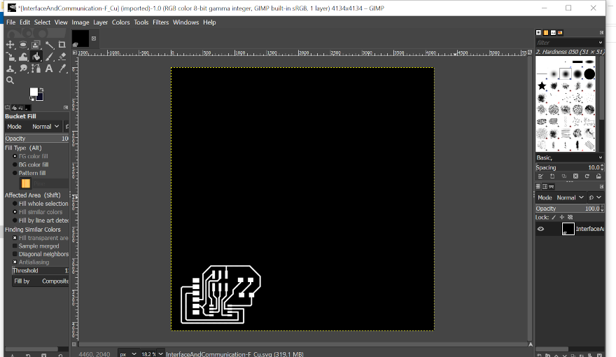
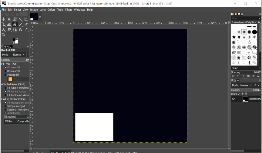
I plotted the above PCB to produce two SVG files(F.Cu and EdgeCuts), I put them in Gimp to produce their respective PNG files for mods to pe printed by our Roland machine. Below, is the F.Cu in Gimp.
Below, is the edgeCuts in Gimp
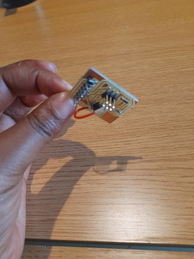
I have used a jumper because this is the second output PCB designed , during the design of the first PCB, I made an unconnected pin error. After finding that in our local fab was no other board to print on my PCB, I tried to solder the first board and use a jumper and it works.
Electronic production
Below, is the produced PCB after passing through all electronic production steps learnt in electronic production assignment.
Electronic programming
I have used the following arduino code to program my output board(to blink the LED connected to pin 4 of ATtiny 45). You can copy the code and reuse it, the only thing to change is declaring and innitializing your LED according to the pin on your microcontroller board where the LED is connected.
int LED = 4;
void setup() {
  pinMode(LED, OUTPUT);
}
void loop() {
  digitalWrite(LED, HIGH);
  delay(1000);
  digitalWrite(LED, LOW);
  delay(1000);
}
Below is my Hero short
Download Files Here
GROUP ASSIGNMENT
The group assignment was to measure the power consumption of an output device; we decide to measure the power consumption of a motor by connecting it to a variable power supply and observe the current drawn by the motor.
Img for experiment