5. Electronics production
My assignment of this week is to make an in-circuit programmer that includes a microcontroller, as extra credit I have to customize the design mill and stuff the PCB, test it to verify that it works and try other PCB processes.
Research
“As I have not any electronic background, to do this assignment I pass through various online tutorias in order to get the meaning of electronic terms in this circuit, which I consider as keys to carry out my assignment, and below is what I found”
In-circuit programmer:also known as In-System Programming (ISP) or In-circuit Serial Programming(ICSP): is the ability of some programmable logic devices, microcontrollers, and other embedded devices to be programmed while installed in a complete system rather than requiring the chip to be programmed prior to installing it into the system. It allows manufactures of electronic devices to integrate programming and testing into a single production phase and save money, rather than requiring and separate programming stage prior to assemble the system.
In-System Programming(ISP):allows programming and reprogramming of microcontrollers,Serial EEPROMS and Flash memories already stored on a target PCB.
What amazed me is to found that in-circuit programmer is a device not a humman being.
As my background is computer science I use to search for the difference between Microcontroller and Microprocessor
Microcontroller:is a mini-computer that is programed to do a specific task; Microcontrollers are used in Appliances or in specific devices to do one thing; microcontrollers doen’t need other part to work, it has a low cost and use low energy. i Their vendors are : ATMEL, ST ,…whereas
Microprocessor need other parts to work and it is used in general computing like Laptops, Tablets and you can send an email by listening to a music means you do different tasks on one micoprocessor, it has a high cost and use high energy.
Their vendors are: InteL, ADM,..
Useful links
To start my assignment, I visit samples of other student given to use, I pass through Electronic production assignment---->In-circuit programming—>in-system development—> then I choose Brian who use Attiny 45 cause I want to use it too.
I have followed steps in building the FabTiny ISP in designing an other version of AVR ISP Programmer/board called FabTinyStar that can be produced in Fab Lab using a milled PCB and rapidly available components, this project designed based on the effort of many people like Zaerc’s Fab Tiny Start page.
Under Brian, I found a document which contain two files and I follows his steps in producing a my In-Circuit Prgrammer(ISP)
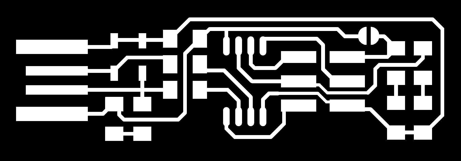
Below, is the dawnloaded first file fts_mini_traces.png
Below, is the second file I have dawnloaded fts_mini_cut.png

We need to translate our files into RML files so that our Fab Lab Roland SRM-20 mill it. I followed steps in a pdf document provided by our local Fab Academy instructor.
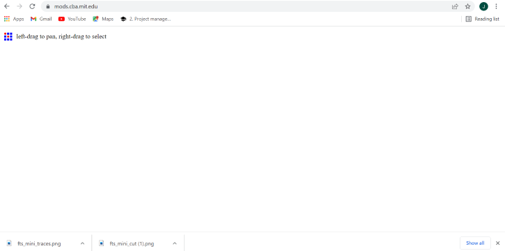
Below, is wat I see when start with openning mods.cba.mit.edu
After Right clicking on the space
Select programs—>open server program
Below SRM-20 select PCB
Below read png select mill traces(1/64)
Below Roland SRM-20 milling machines set orgin x,y,and z to 0,0,and 0
This is what you see after those settings

Then after, Select modules–>add server module
Under file select save and a save file module will open in the main window
Below is what you see and the save file module open

Left click and hold on the save file text, and move it down between the Roland SRM-20 milling machine and the WebSocket device
Use the mouse curser to go over the file in Roland SRM-20 milling machine output file, when the line that goes out from the square is highlighted, then left click; highligth the file(object)in save file input file(object)and left click.
In mods mill raster 2D click on calculate, then a rml file will be downloaded to your Downloads directory(This happens every time you click on calculate).The dawnloaded file you see is the produced RML file for the enterd fts_mini_traces.png file.
Below is what you see after following the above steps.
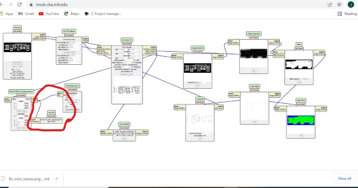
You can see the toolpath if you click on view toolpath** mods.
Repeat the same procedures for producing fts__mini_cut.png RML file
But under set PCB defaults, select mill outline(1/32) other steps are the same means you have to pass through all of them.
Below is what you after finishing the last step, also your RML file produced and dawnloaded

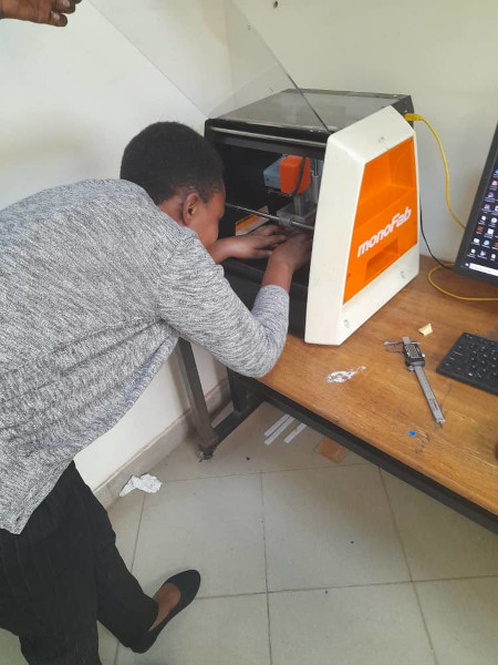
After producing my two RML files,I put them onto my flash disc and go for RSM-20 to read them. Arriving on the RSM-20, I followed the following steps to produce my first circuit board.
Below, I have started VPanel for RSM-20 software to control the machine in its work of producing my In-Circuit programmer then set my cutter level correctly by with the help of axis It has x,y axis to move the Roland machine board along those axis and z axis to move the mill bit handle up and dawn for well fixing the bit to the board according to where you want your circuit board to start from.

-Set Zero level for the SRM-20 cutter: set x,y, and z to zero or start with setting x and y to zero then z after; you may gain a chance to tell x and y to start to their first origine.
-Click on cut
-Delete all files founded in
-Add to add my RML file
-Click on Output, and The SRM-20 start the cutting.
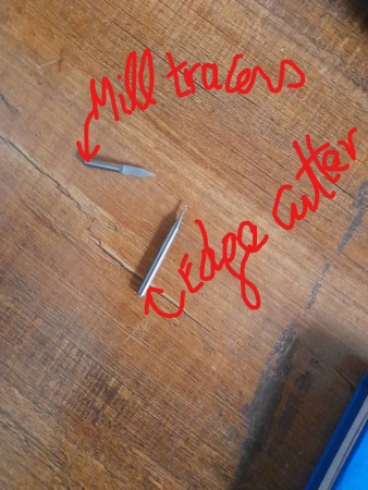
Below, are Mills I have used to produce my ISP, one for tracing and other for edge cut as shown.
Below, Roland machine mill tracing

Below, is my ISP produced before adding on its edge cut

Below, is me changing the mill bit to the one for cutting its edge mill
Below, is the produced ISP

Soldering
After getting my board then I collected all components to be solded on my ISP. Soldering electronic components was a problem for me because they are small devices and I use to fear electric current used but I tried my best and do it. After soldering I found one small route has no connection then I use jumper to get that connection.
Below, I was sldering my programmer

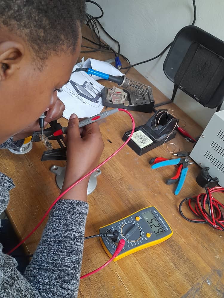
I have used Multimeter measuring continuity and Below I was using it to read my resistance value.
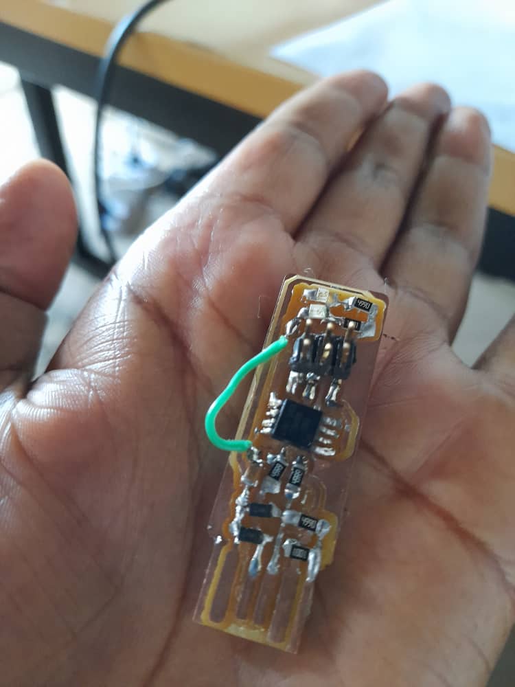
Below is the produced programmer and because one route of my programmer has no continuity due to its thickness, I have used a jumper to correct it and it works.
Programming:
Now, It’s time to program my ISP to become a programmer, I need a well working programmer and I have used arduino programmer given by our Local instructor and follow instruction provided in Brian’s document.
First, I downloaded week__5 folder from the link our local instructor provided to us then I unzipped it to access its files and folders inside it I found fts_firmware_bdm_v1.zip I unzipped it too to access its files and I found the file I was searching for which is Makefile. I have used Git Bash command interface and navigate various commands on the content of Makefile:
make flash: It is a command used to load my chip to the used arduino programmer .
make fuses: Is a command used to program my chip, to make it a programmer. Then I removed my ISP from the arduino programmer and putted on my laptop.
lsusb: I have used to check if my chip was programmed and I saw that a file Multiple … was created means that it is programmed then I have removed my programmer and connect again to the arduino programmer.
make rstdisbl: This is a command used to delete unneccessary automatic created files.
Below, is Git Bash in searching for Makefile

Programmer in Use
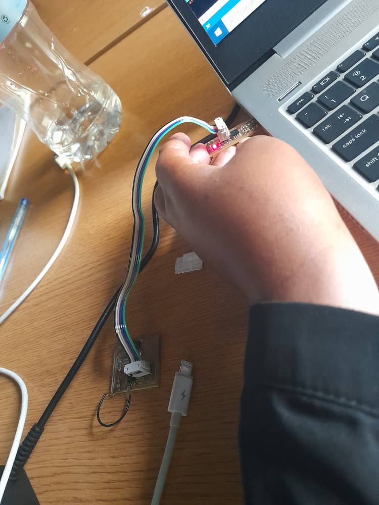
Because my programmer has a jumper even though it is working I was not confortable with it as we need to use it to program other boards in the continous assignments. I realise that the thickness error of my programmer was caused by the used mill bit, I changed it and With SRM-20 Roland machine, I milled an other programmer, solder it and program it by following the same steps as I did for the first programmer. Below I have using my second programmer to program my slave board on Networking and Communication assignment here.
File Used Here