7. Electronics design
For this week assignment, I have to redraw an echo-world board, add at least a button and LED(with current limiting resistor) check the design rules, make i, and test that it can communicate. As extra credit I have to simulate its operation.
Designing electronics
To carry out this assignment, I pass trough various online tutorials looking on how can I design my own PCB(Printed Circuit Board), I found that there are many softwares like Altium Designer 2.0, Eagle, Kicad,…that can help me in designing my own circuit, I watch out short video on Eagle and Kicad, then I prefer Kicad than Eagle because it has helpful tools which are understandable.
First, I dawnloaded kicad software here and install it on my laptop
Second, with the help of our local teacher Fred, I add Kicad libraries got from Fab Lab resources in my local machine Kicad Library in order to use them in designing a feasible circuit board, means in testing if my circuit board is working, I will need phyisical electonic devices which are available in our FabLab.
After installing kicad software File–>New Project then they ask you to type in your project file(file name) you need to save your project under. After saving automaticaly two files are created under the name of your project. For instance my project name is UpdatedFinalHelloWord I found two files under it: UpdatedFinalHelloWord.kicad_pcb and UpdatedFinalHelloWorld.kicad_sch.
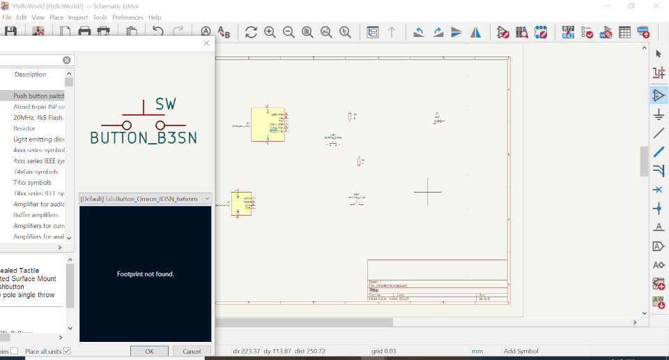
Below, is what I see when I click on UpdatedFinalHelloWrld.kicad_sch_, it provides a paper to put on your electronic devices you need to design your circuit board.

I have used Add a symbol button to add on devices which I want to make my Updated Hello World circuit. By cliking on Add a symbol button, immediately symbol library start loading and an interface open allow you to choose a symbol you want , for example I need a Button, I have to search for Button I want by viewing different button images and choose it,click Ok, then clicking any where in the interface a choosen button will be added on As shown below
To move, to rotate, to delete a symbol, select that symbol using select tool and type on your Keyboard.ctrl+M to move, ctrl+R to rotate, and delete to delete that symbol. After adding on all needed symbols, you will see that they come with question marks(?) for example R?, instead of R1 Or R2 to correct that issue, you have to annotate your schematic by chosing on menu toolbars Tools—>Annotate Schematic.
Now, its time to connect your symbols; You may use wires connection or Labels. For me I choose to use add a net label button, which is easy, because many wires may lead me to a complex design and it can complicate me in generating my circuit as a beginner.
Below, what you see is a complete connected HelloWorld schematic circuit.

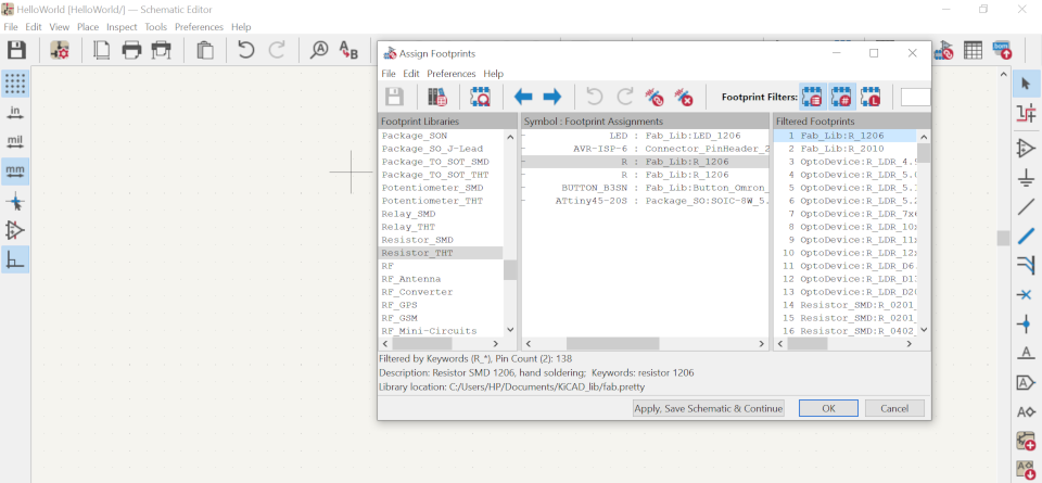
Below, is After Assigning Footprints by choosing Tools—>Assign Footprints and this help you to correctly choose specific electonic devices you want according to what you need,by selecting in footprints list by footprint filters defined in the symbol and footprints list by pin count and you may see their pictures to help you choosing in highilighting View selected footprint in footprint viewer. When you are done with footprints click Apply, Save Schematic and continue then click Ok and the above window will be opened.
After assignning footprints, go to Tools–>Switch To PCB Editor again Tools—>Update PCB from Schematic , you will get a warning message if tatal errors are Zero Click Update PCB then Close As shown bellow.

Below, is what you see After choosing Close, a small image of PCB generated, then you have to zoo in to view it nicely.

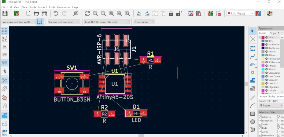
Below, is when I start to arranged my PCB ** in an easy and understandable way, which will help me in adding tracks to my circuit board.
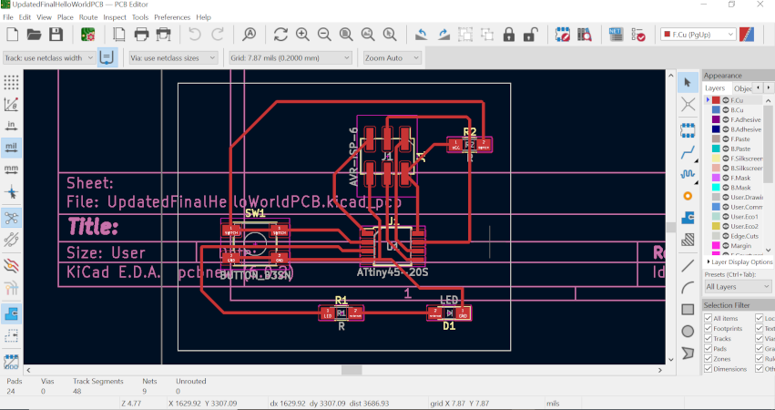
Below, is when I have add on tracks to my board, when you select a symbol with a track tracer holding on your mouse, it shows you all symbols connected to it and follow the path to route them then unrouted reduced, when unrouted is equal to Zero, you are done with tracks on your board.
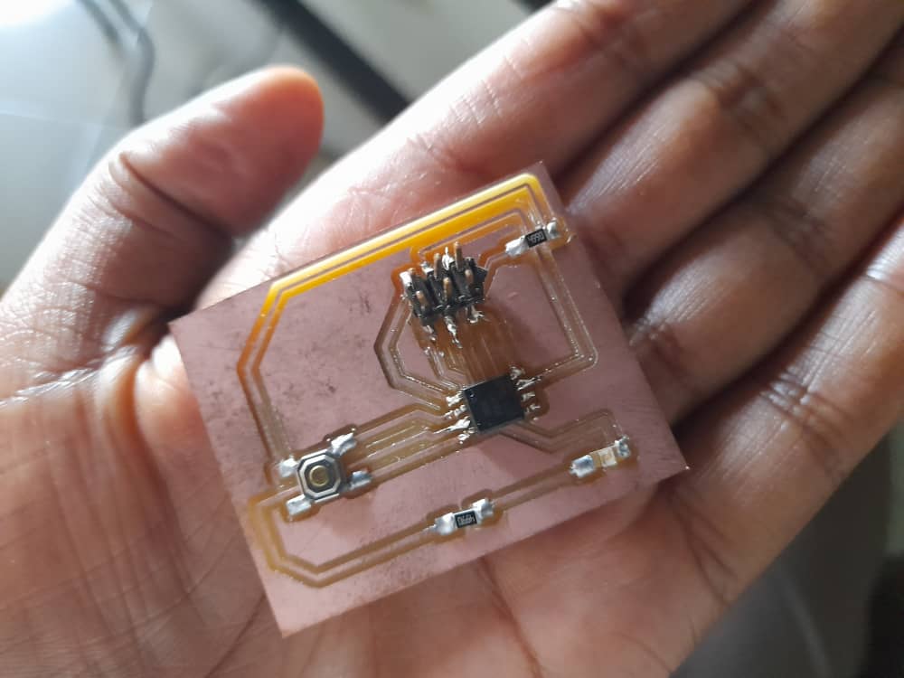
Unrouted reaches Zero, then am done and my PCB is complete** then I have added edge cat and paper set up.
Below, is my PCB 3D view using 3D Viewer you will be able to see how you PCB will look like after printing it and adding on your electonic devices.

Electronics production
After getting the above PCB, I plotted it to obtain F.Cu and EdgeCut SVG files and I opened them individually with Gimp software to produce F.Cu and EdgeCut PNG files and I passed them in mods to produce F.Cu and EdgeCut RML files to be milled by our SRM-20 Roland machine to produce the designed PCB; Then I collected all electronic devices to solder on my Hello World PCB which are: 1ATtiny45, 1ISP-AVR, 1 Switch(Button),2Resistors, and 1LED. I solded them on as I did on electronics prproduction assignment and below, is my solded HelloWorld PCB.
Next, Its time to program my board. I opened arduino and open File–>Examples–>Basics–>Blink and initialise LED to PB4 and Button to PB3 and Below are Blink code used, you can copy them and reuse them too.

Under Tools I select Board –> ATtinyCore–> ATtiny45 and for programmer I selected ISP and I test the code and I found that there is no error and I run them by selecting Sketch–> Upload Using Programmer then my LED blink as you can see below, now my PCB is working.

File I have used Used Here
GROUP ASSIGNMENT:
The group assignment was to use the test equipment in our local fablab to observe the operation of a microcontroller circuit board.
Reasearch
To carry out this assignment we have first identify the test equipments found in our lab and below are found test equiments:
1. Multimeter
Multimeter is a measuring instrument that can measure multiple electrical properties such as voltage, current, resistance, and is also known as VOM as the unit equipped with Voltmeter, Ammeter, and Ohmmeter functionality; A device to measure electrical quantities and can be used also to measure electrical functions such as Voltage, Current, resistance, and can be able to measure electrical frequency. Below is the image of a Multimeter

Below, is me using multimeter to check current continuity on my board.

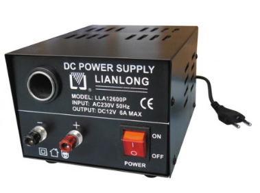
2. Power Supply
Power supply is an electrical device that supplies electric power to an electrical load; Its purpose is to convert electric current from a source to the correct voltage, current, and frequence to power the load. It is also reffered as electric power converter.
3. Digital Oscilloscope
Digital Oscilloscope is a complex electonic device constisting of various software and electronic hardware modules that work together to capture,process, view, and store data represanting the relevant signals of an operator; It is reffered as Digital Storage Oscilloscopes(DSO)or Digital Sampling Oscilloscopes(DSO).
6 Digital Oscilloscope elements:
- Analog Vertical Input Amplifiers,
- Analog-Digital Converter And A Digital Waveform Memory
- A Time Base with a Trigger And Clock Drive
- Circuits for Waveform Displaying and Restructuring
- LED or LCD screen
- Power source
Digital Oscilloscopes work on the principle of sampling the signal from input thanks to high-speed microprocessors and you can be able to stop it at any time, trigger it at the desired level, recorded, and created again.
Digital oscilloscopes periodically sample a time-varying analog signal and store the signal values in relation to time in the waveform memory. Using built in clock, digital oscilloscopes compress input signals into separate time points; Instantaneously amplitude values are measured by an oscilloscope at that point, the resulting digital displays are then Stored in a digital memory.
Digital Oscilloscope has the ability to store digital data for instance viewing, uploading to acomputer, creating hard copies or storing it on floppy disk,and measuring instantly on digital data over analog oscilloscope. After triggering event, digital oscilloscopes can display waveforms, while an analog oscilloscope needs to trigger before starting watching.

Download files used here