15.MECHANICAL DESIGN, MACHINE DESIGN
Assignment Requirements:
.Mechanical Design (part 1 of 2)
.Group assignment:
-Design a machine that includes mechanism + actuation + automation
-Build the mechanical parts and operate it manually.
-Document the group project.
.Individual assignment:
-Document your individual contribution.
Machine Design (part 2 of 2)
.Group assignment:
-Actuate and automate your machine.
-Document the group project.
.Individual assignment:
-Document your individual contribution.
Learning Outcomes:
.Work and communicate effectively in a team
.Design, plan and build a system.
.Analyse and solve technical problems.
.Recognise opportunities for improvements in the design.
Introduction
laser cutter/engraver machine
Laser cutter/engraver is a type of laser machine with CNC (Computer Numerical Control) system that adopts Fiber/UV/CO2 laser beam to cut & engrave 2D letters, numbers, texts, patterns, photos, pictures, signs or logos on the surface of the materials.Laser has four main characteristics: high brightness, directivity, monochromaticity and coherence.so it has been widely used in industrial processing.
Application
Laser engraving machine is an intelligent laser engraving device for personal or enterprise applications. It can be used to perform specific tasks i.e Used for carving pictures, words, tracks or cutting the surface of general non-metallic materials! Suitable for all kinds of DIY artworks.
Automation
Automationdescribes a wide range of technologies that reduce human intervention in processes.
Automation – specialist in power transmission and motion control
We supply slewing ring bearings, oscillating mountings, addition we also select and offer the right components and systems for motion control solutions, such as stepper gear motors, linear stepper actuators and complete XY cartesian systems.
Actuation
Actuation. An actuator is a component of a machine that is responsible for moving and controlling a mechanism or system.it is mover.
From the point of view of machine design, Actuators are the parts of the machine that operate in its environments ( to affect it/change it, in some way), while the limit sensors are the parts that receive information from its environment.
In terms of actuation, our machine has a moving laser beam, whose tip can be arbitrarily positioned in any position in the operating space/volume.
For all intents and purposes, however the laser beam will only occupy 2 planes in space:
The paper plane: when the tip of the laser beam is touching the surface below the machine. This setting can be used to write, draw on it or mark it in some way.
The hover plane: when the tip of the laser beam is held away from the floor/paper/whiteboard. This position allows us to freely move the laser beam without leaving marks or painting anything.
Mechanism
Mechanism, rigid bodies connected by joints in order to accomplish a desired force and/or motion transmission
The machine that we have built has various mechanisms to operate and perform action in all 2 spacial dimensions:
1 mechanism to operate on the X axis using 1 stepper motors.
2 mechanism to operate on the Y axis using 2 stepper motors.
The mechanisms allow the machine to have an operating area of approx:
60mm * 30mm = 180mm
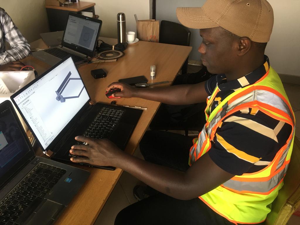
Mechanical Design
In designing we use solidworks software, we started out with an already existing frame made with aluminium profile and had to add, - X- Axis: 2 acrylic plates as holders for 2 steppers motors. - Holders laser cut in 5mm acrylic sheet to hold the stepper motor, wheels/bearings,cornel blackets and a provision for endstoppers. - Y xis: Aluminium profile frame attached to the 2 X Axis acrylic plates and an extension for the Z axis. - Z Axis: A stationary plate extension and a stepper motor with a laser beam attached to it.
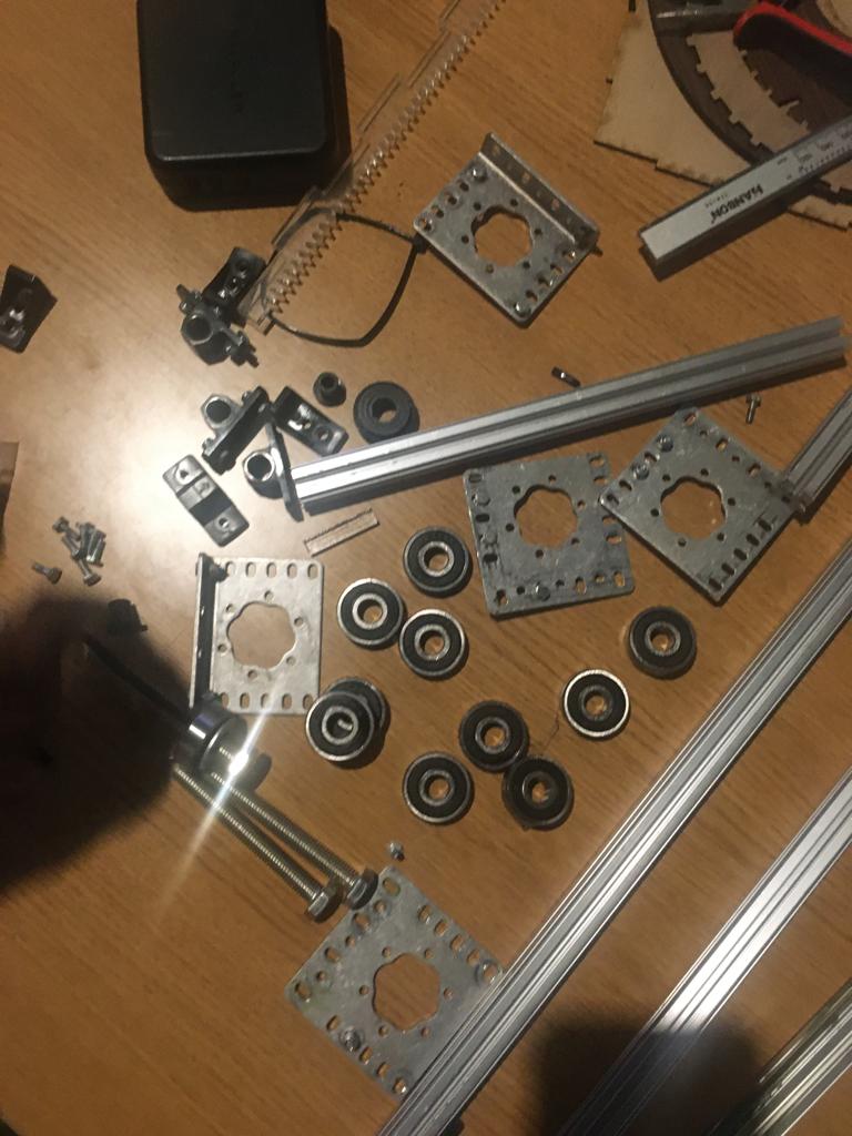
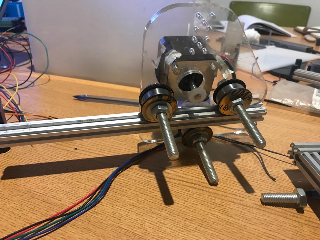
Below is bearings to be fixed to stepper motors
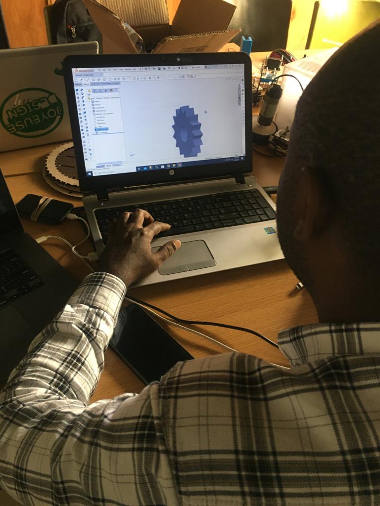
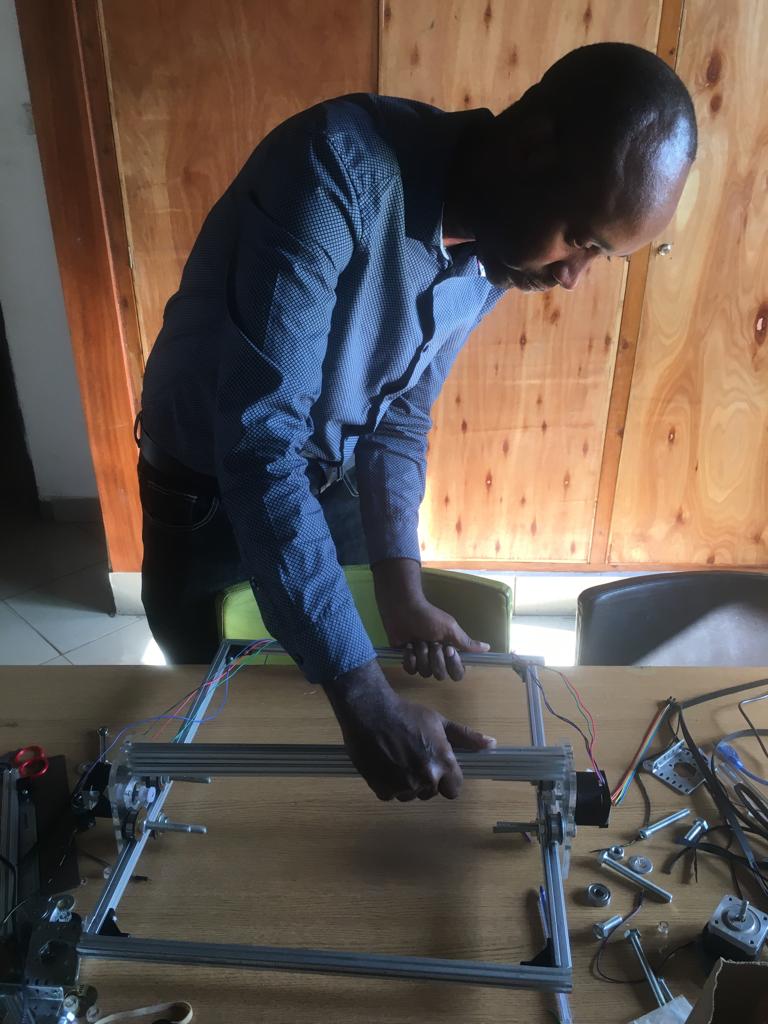
Below is our laser cutter/engraver machine we designed and assembled using solidworks.

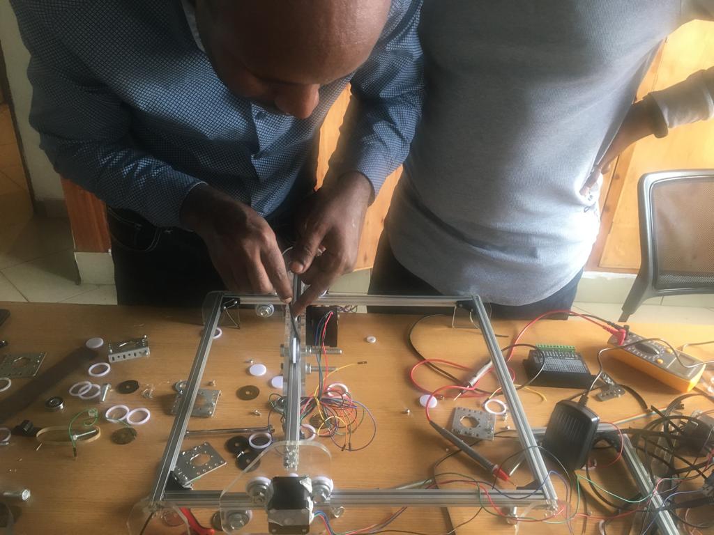
Mechanical Design and assembly of laser cutter/engraver machine 
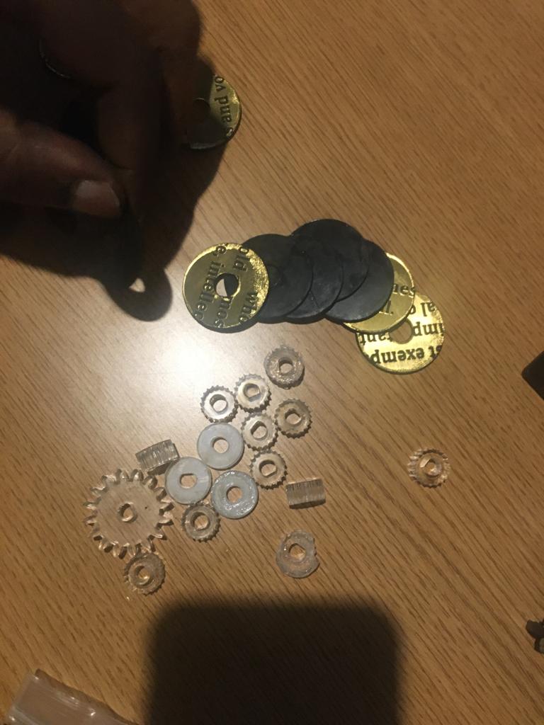
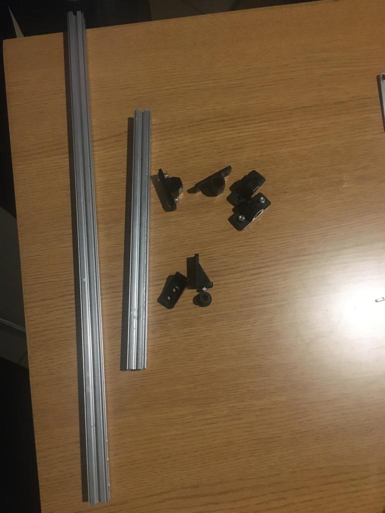
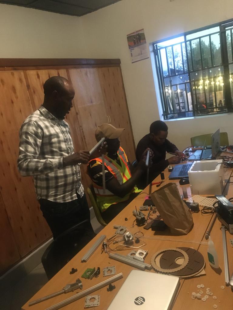
Parts and Tools: the first 2 images includes all the components that we need to start assembly. To make things easy I suggest to add to the included tools also a plier,razorblade before starting the assembly job.
The components below are:caplers,bearings, washers,aluminium profile,cornel rackets,stepper motors, bolts and nuts.
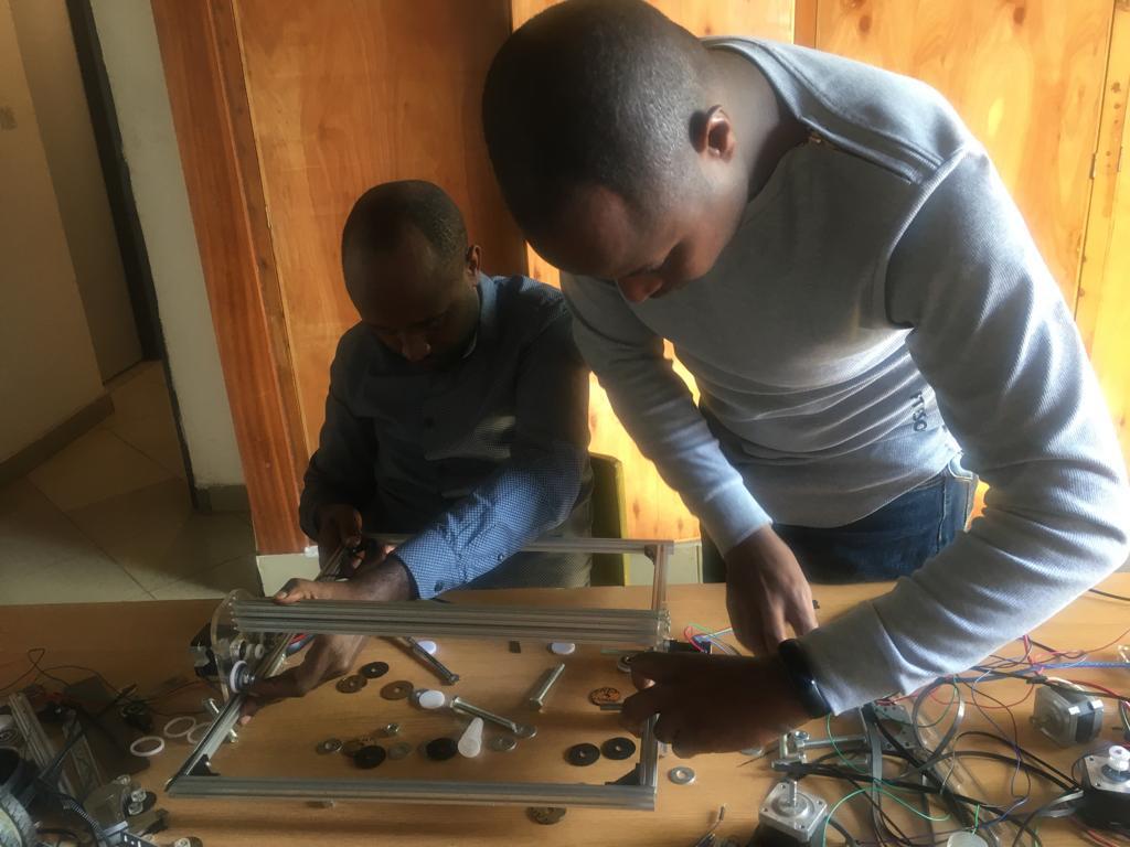
Assemble the Main Frame:the main frame (the base of the engraver) is very easy to assemble but insert the nuts and cornel brackets inside the profiled Aluminium longer sides.
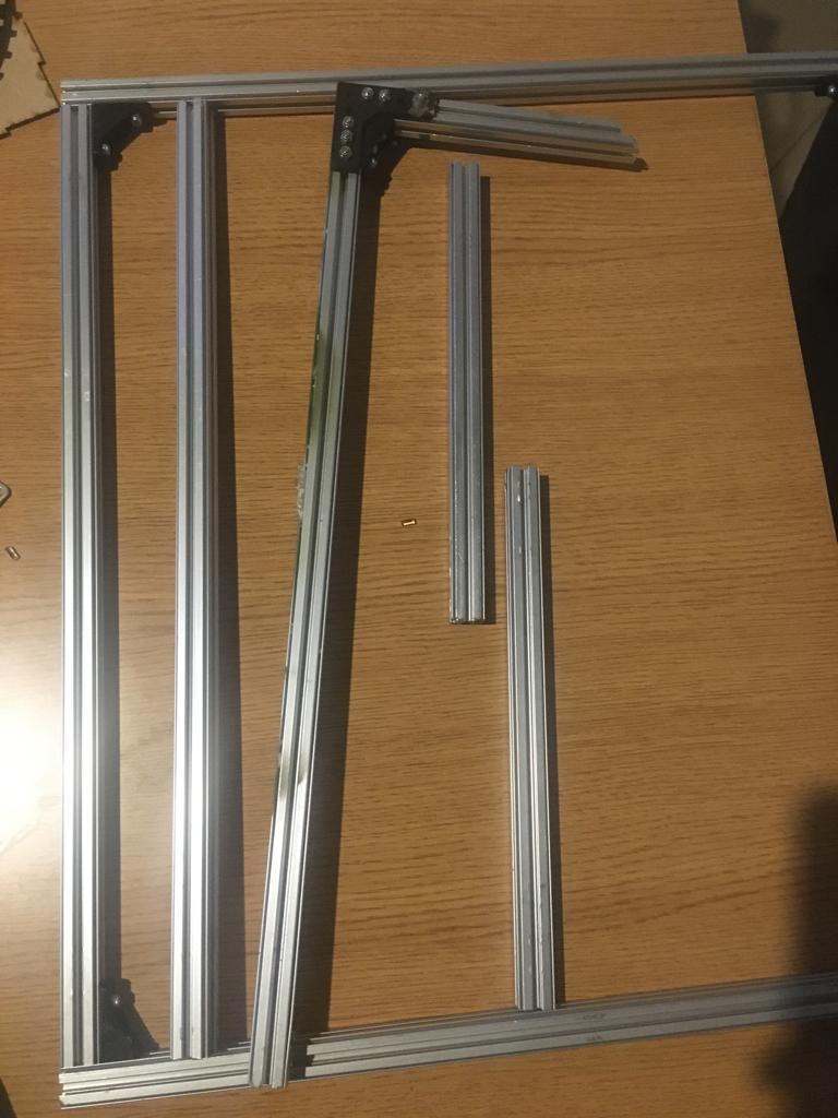
The Supports to the Main Frame: The short Aluminium profiled supports are aligned to the top of the longer side supports and are in direct contact with the front and rear acrylic sides, contributing to give robustness and stability to the frame. As we see further in this way the main frame has a border available to place a flat base on which we will position out pieces to cut or engrave.
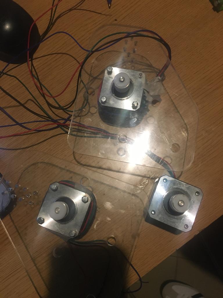
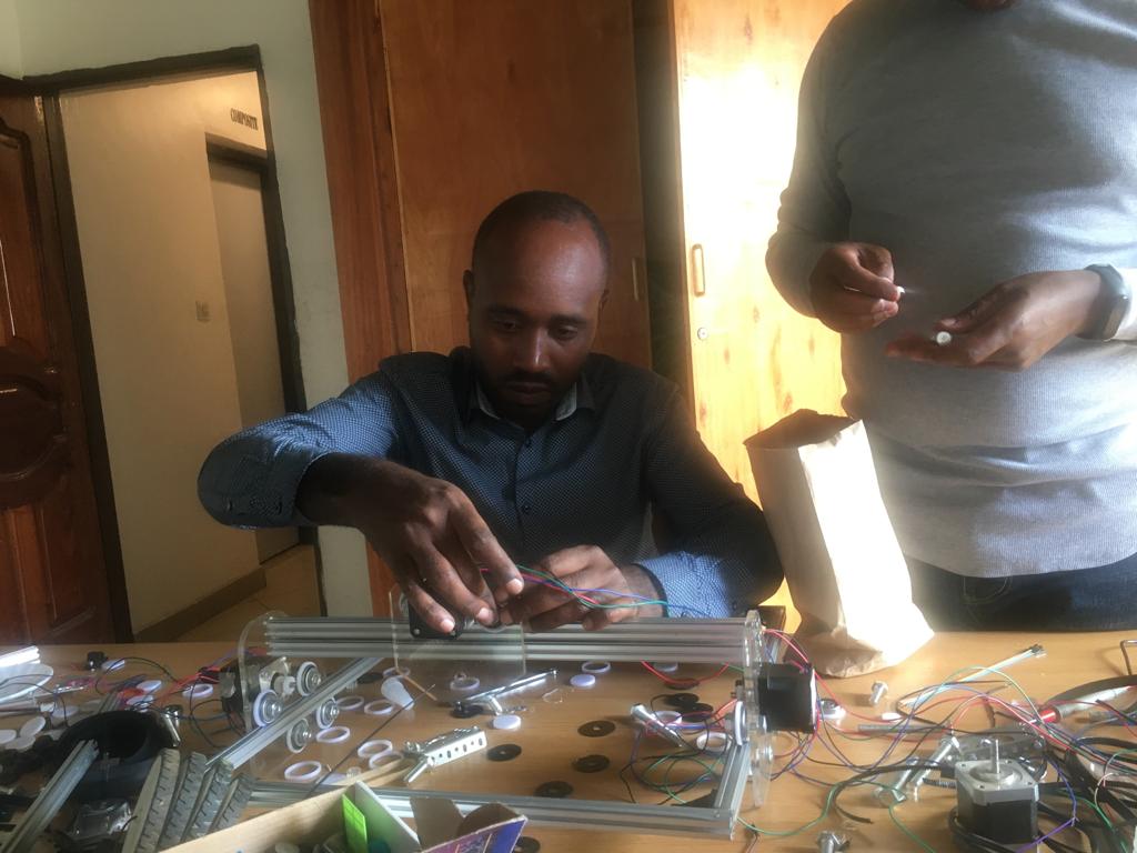
Assembling the X and Y-axis Stepper Motors:In this step we will assemble the 3 stepper motors that control the X-axis and Y-axis.
To complete this step you will use: three stepper motors, three acrylic Y-axis supports, three teeth pulley and eight M3 allen screws.
Below, we are arranging all components to be used in assembly of main frame.
Below,we are are fixing aluminium profile using cornel locking and nuts.
fixing the belt to side of aluminium.
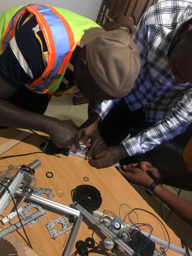
Fix acrylic belt locks to the aluminium profile:As shown in the image below insert the M3 (smaller) Allen screw in the smaller hole and the nut in the other side. Close it with hands without blocking.
Slide one of the two M4 nuts that you have inserted in the frame in the step Assemble the main frame to one of the extreme sides of the rail.
Assembling the Y-axis Stepper Motors:In this step we will assemble the two stepper motors that control the Y-axis.
To complete this step you will use: two stepper motors, two acrylic Y-axis supports, two teeth pulley and eight M3 allen screws.
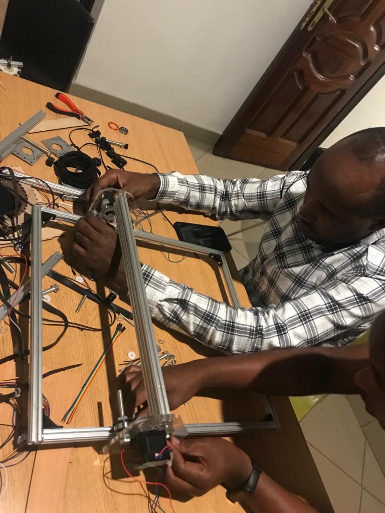
Adding the X-axis Support:The Y.axis moves along the longer side of the frame using two stepper motors synchronised. Now we should assemble the top Aluminium profiled support that holds the X-axis and laser head group and keep the two sides Y-axis motors perfectly aligned.
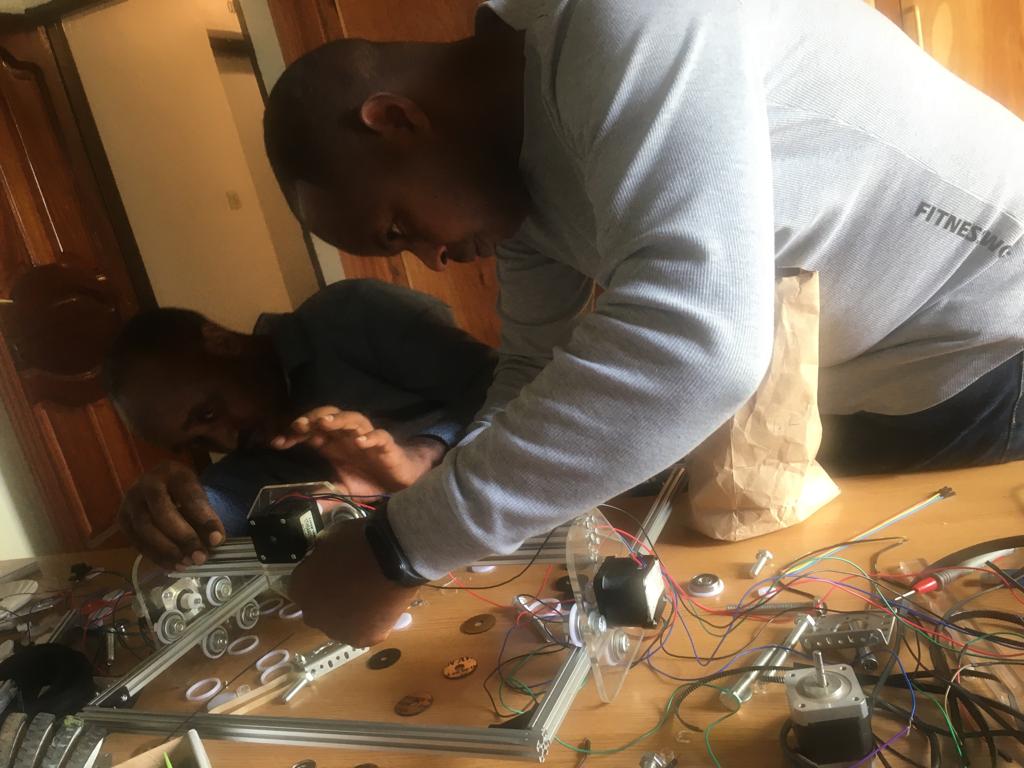
Assembling the Y-axis Bottom Bearings:This is the step where we start mounting moving parts together.
To complete this step you will use: the two Y-axes motor group , M3 Allen screws and nuts, washers, plastic separators, bearings.
Assembling the X-axis Stepper Motor:The assembly instructions for the X-axis stepper motor is the same as explained in Assembling the Y-axis stepper motor.
To complete this step we have used: one stepper motors, the motor side acrylic X-axis support, one teeth pulley and four M3 allen screws.
Fixing the belt to the all side and tensioning:Now that the teeth belt is firmly fixed to the first side, insert it in the rail and dispose on the motor teeth pulley as shown in previous images. Don’t care to tension the belt now.fix the belt to the remaining parts of aluminium.
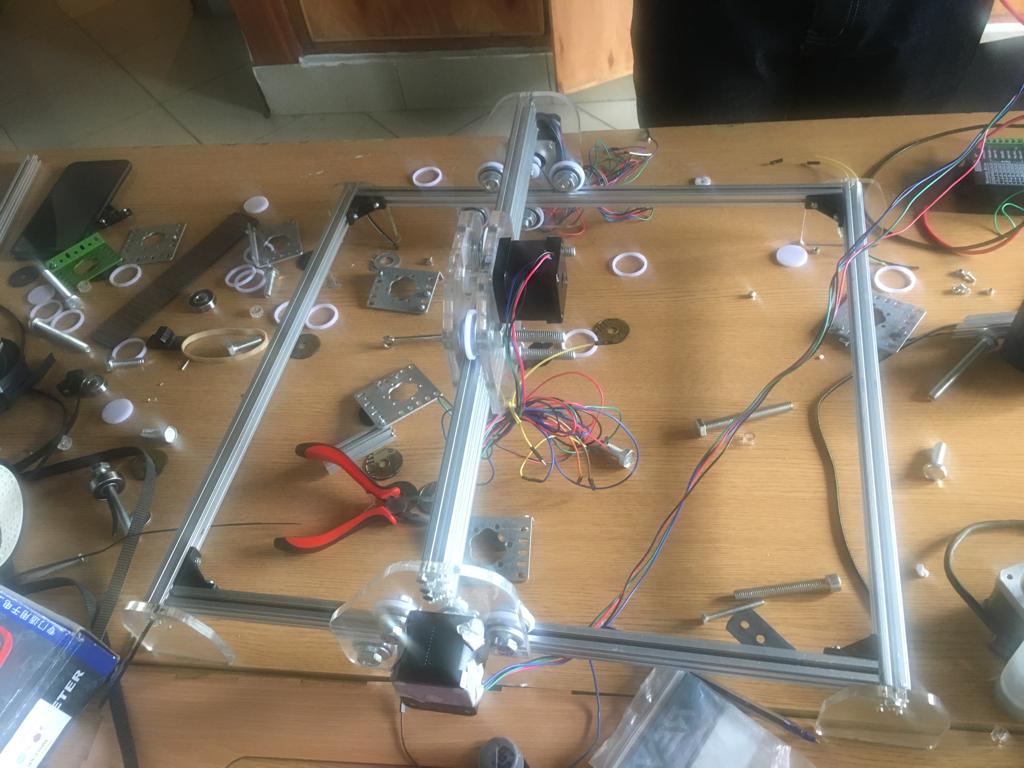
Below is finished assembly of laser cutter/engraver machine.
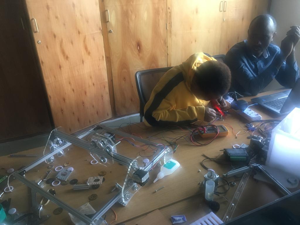
During electronics design and implementation
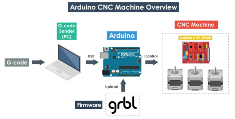
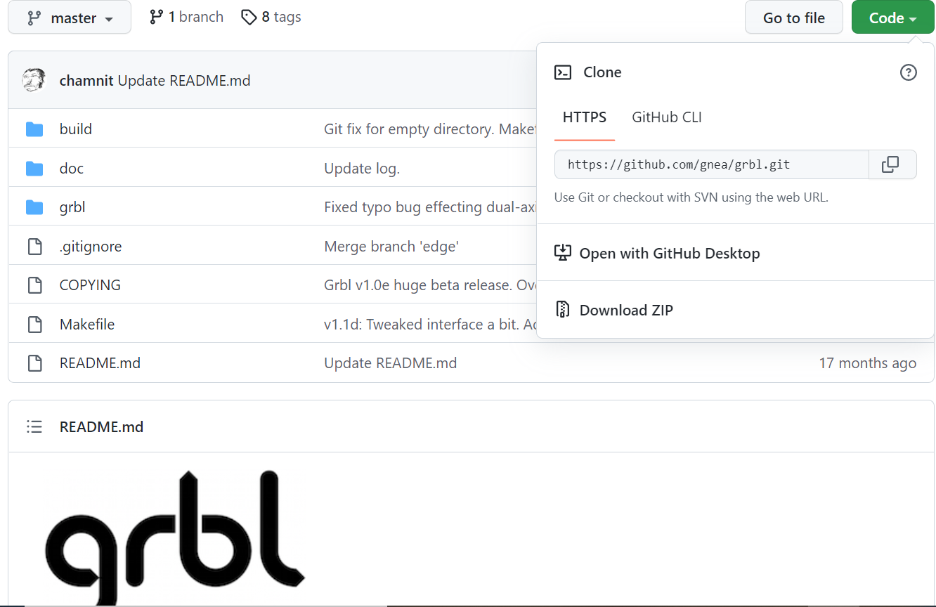
What is GRBL
GRBL is an open source software(firmware) which enables motion control for CNC machines; The GRBL uses G-code as input, and outputs motion control via the Arduino. Below you can see the concept
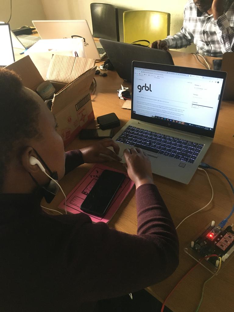
How to install GRBL
GRBL is a firmware that we need to install/upload to the arduino so that it can control the stepper motors of the CNC machine means its function is to translate the G-Cod
Follow these steps
-
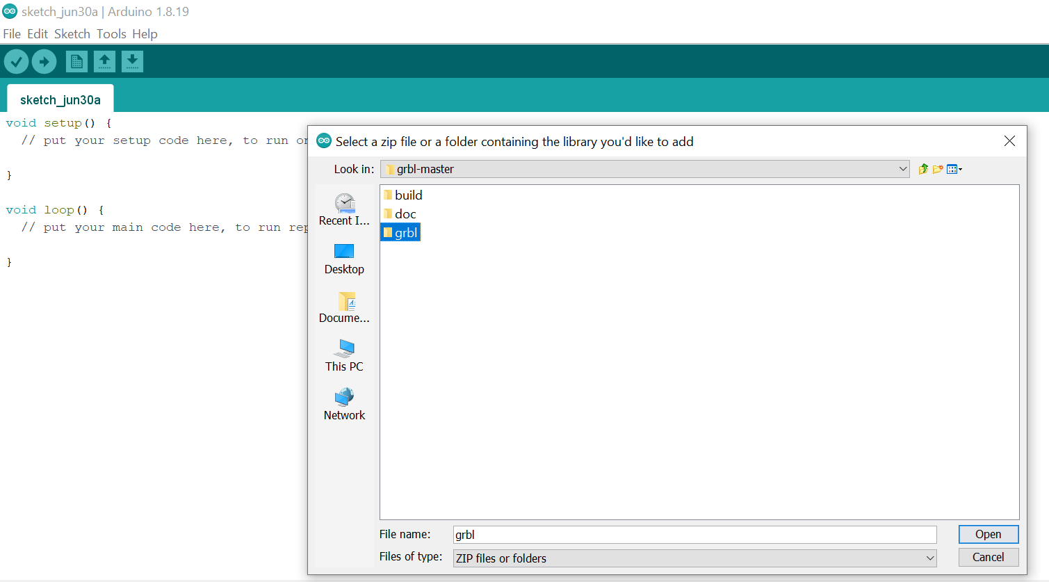
Extract files from the zipped one, Navigate to the extracted folder “grbl-master”, in there select the “grbl” folder and click the open file. Now we have to GRBL as an Arduino Library.
-
Next, navigate to File > Examples > grbl > grblUpload. A new sketch will open and we need to upload it to the Arduino board.
GRBL configuration
At this point we should configure the GRBL to our machine. We can do that via the Serial Monitor of the Arduino IDE. Once we open the Serial Monitor we will get a message like “Grbl 1.1h [‘$’ for help]”. With the baudrate of 115200.
If we type “$$” we will get a list of commands or current settings as below:
$100=250.000 (x, step/mm)
$101=250.000 (y, step/mm)
$102=3200.000 (z, step/mm)
$110=500.000 (x max rate, mm/min)
$111=500.000 (y max rate, mm/min)
$112=500.000 (z max rate, mm/min)
Which means how many steps the motor should make in order our X axis to move 1 mm for example on the first statement. We leave them as they are. And we will adjust them according to our machine using the controller software.
GRBL Controller
So once we have installed the GRBL firmware, now our Arduino knows how to read G-code and how to control the Laser machine according to it.To send the G-code to the Arduino we need interface or a controller software which will tell the Arduino what to do.We have used open source interface which is Univarsal G-code Sender. And below is the our interface we are using.
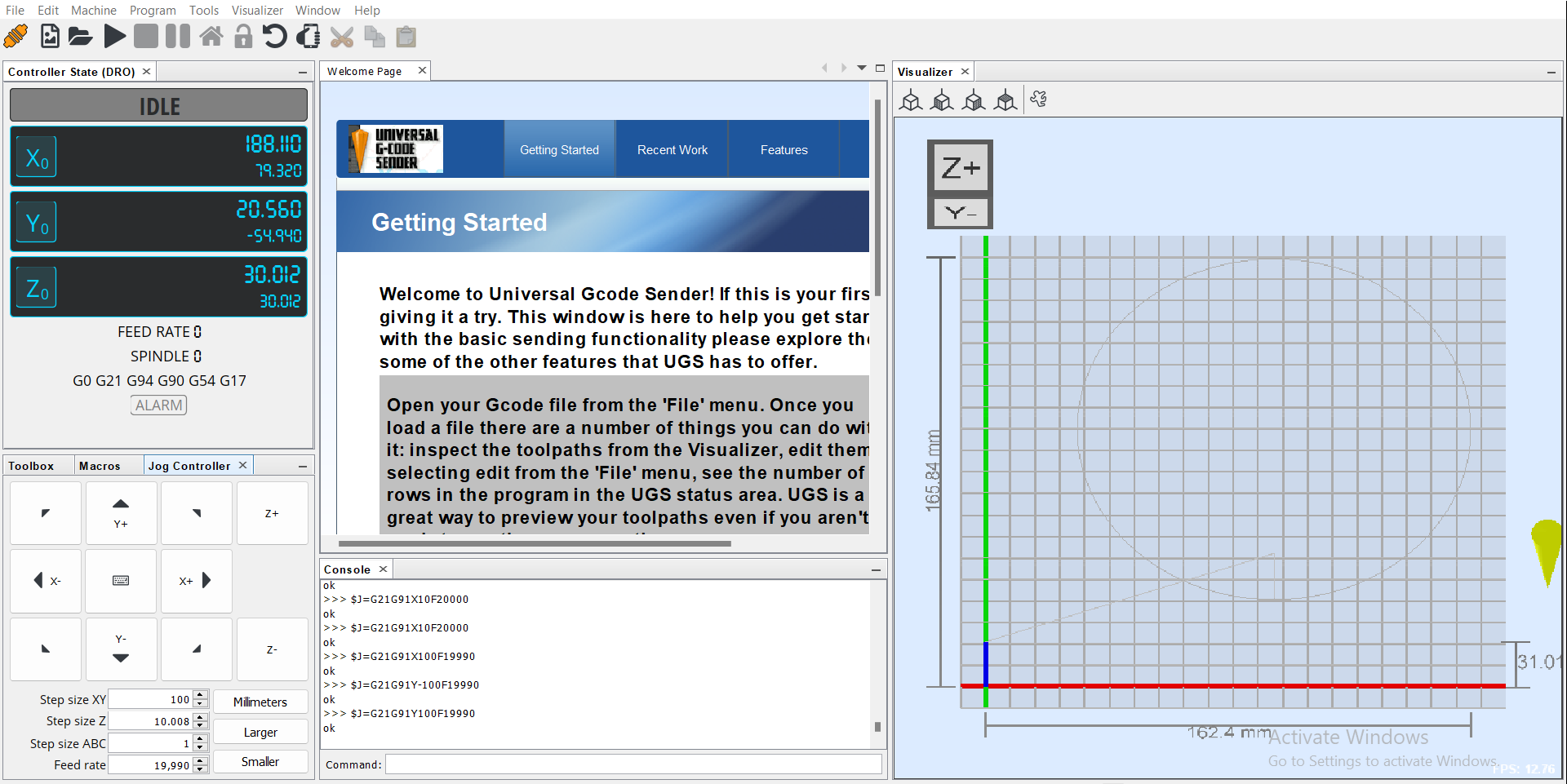
We have completed the laser cutter assembled. Now we can test and enjoy with a new tool.
Download files here