14. Networking and communications
Individual Assignment: Design, build, and connect wired or wireless node(s)with network or bus addresses.
Group assignment: send a message between two projects.
A bus network: is a local area network topology in which each node a workstation or other device is connected to a main cable or link called a bus.All connected stations on the bus can communicate with all others on the singular network segment.
A network node sits at a point in the network where it sends, receives,stores or creates information. It transmits data to communicate with other nodes in the network.
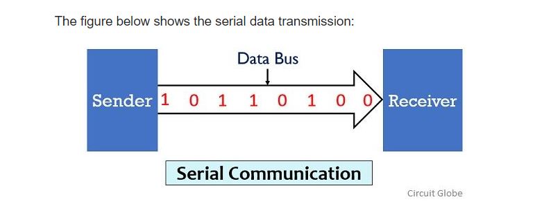
A serial communication
In serial communication, data is in the form of binary pulses. In other words we can say Binary one represents a logic HIGH or 5V and zero represents a logic LOW or 0 volts. Serial communication can take many forms depending on the type of transmission mode and data transfer.
Wiring and Hardware
Aserial bus consists of just two wires- one for sending data and another for receiving.As such, serial devices should have two serial pins: the receiver, RX, and the transmitter, TX
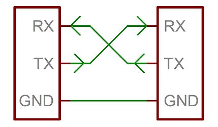
It’s important to note that those RX and TX labels are with respect to the device itself.So the RX from one device should go to the TX of the other,and vice-versa.It’s weird if you are used to hooking up VCC to VCC, GND to GND, MOSI to MOSI, etc..,but it makes sense if you think about it. The transmitter should be talking to the receiver, not to another transmitter.
I2C communication
I2C combines the best features of SPI and UARTS. With I2C, you can connect multiple slaves to a single master(like SPI) and you can have multiple masters controlling single, or multiple slaves.This is really useful when you want to have more than one microcontroller logging data to a single memory card or displaying text to a single LCD.
Like UART communication, I2C only uses two wires to transmit data between devices:
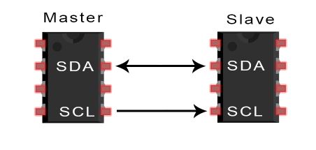
SDA(Serial Data)-The line for the master and slave to send and receive data.
SCL(Serial Clock)-The line that carries the clock signal.
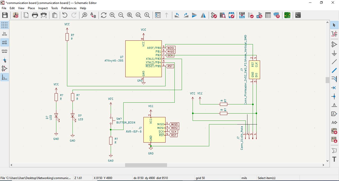
Master Board
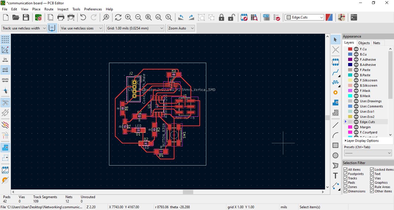
I designed the schematics and PCB design for the master board.
With PCB i have to make plot to produce F.CU svg and Edge cuts files.
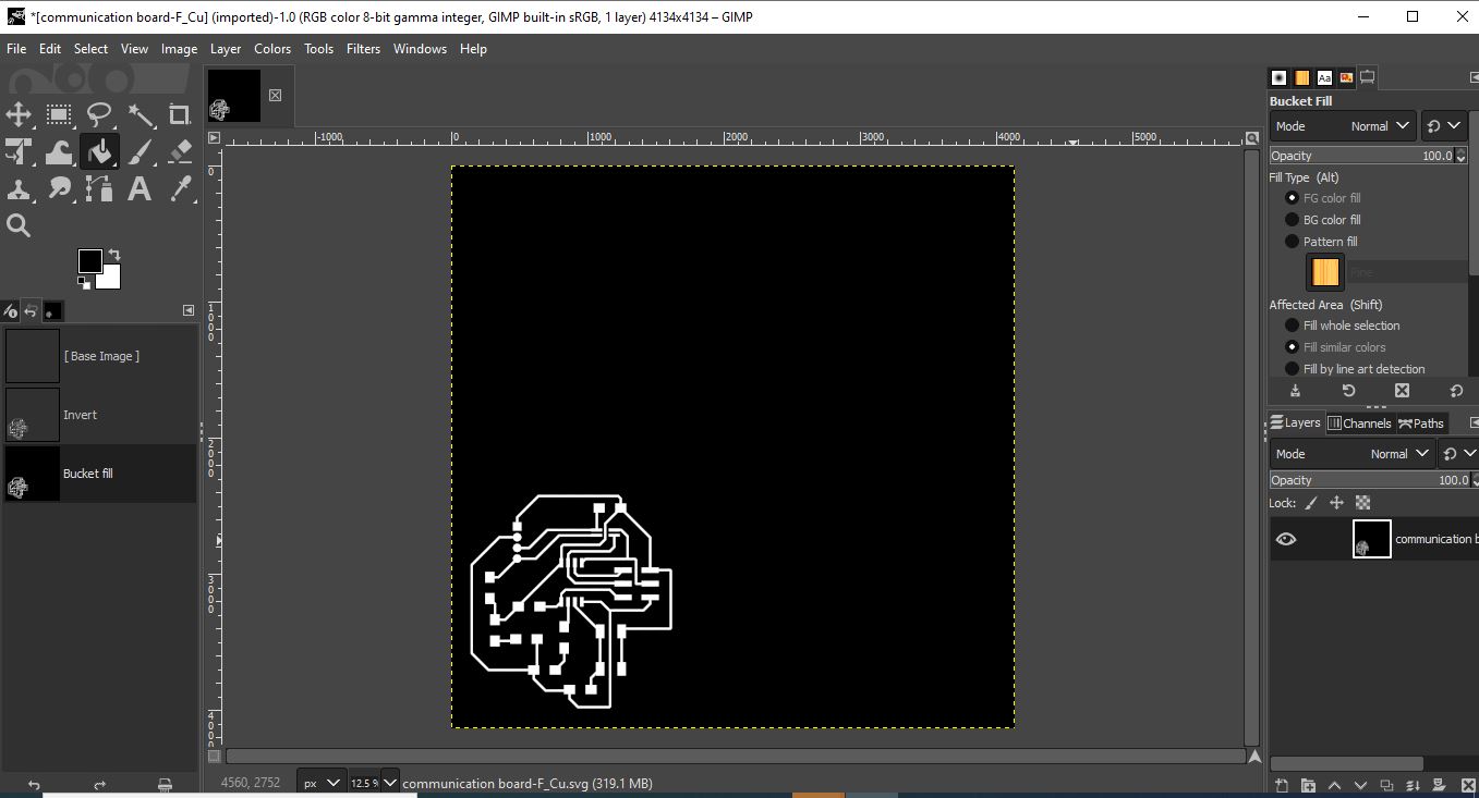
Below, is F.CU image in Gimp to produce F.CU PNG to export in mods.
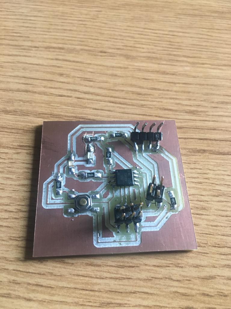
Below is my master board with solidered components.
Slave Board
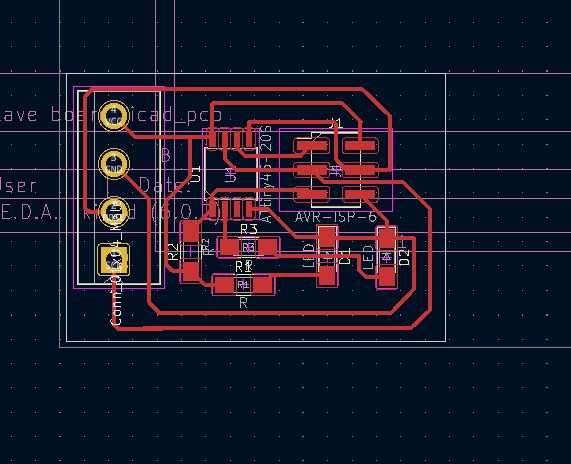
I designed the schematics and PCB design for the slave board.
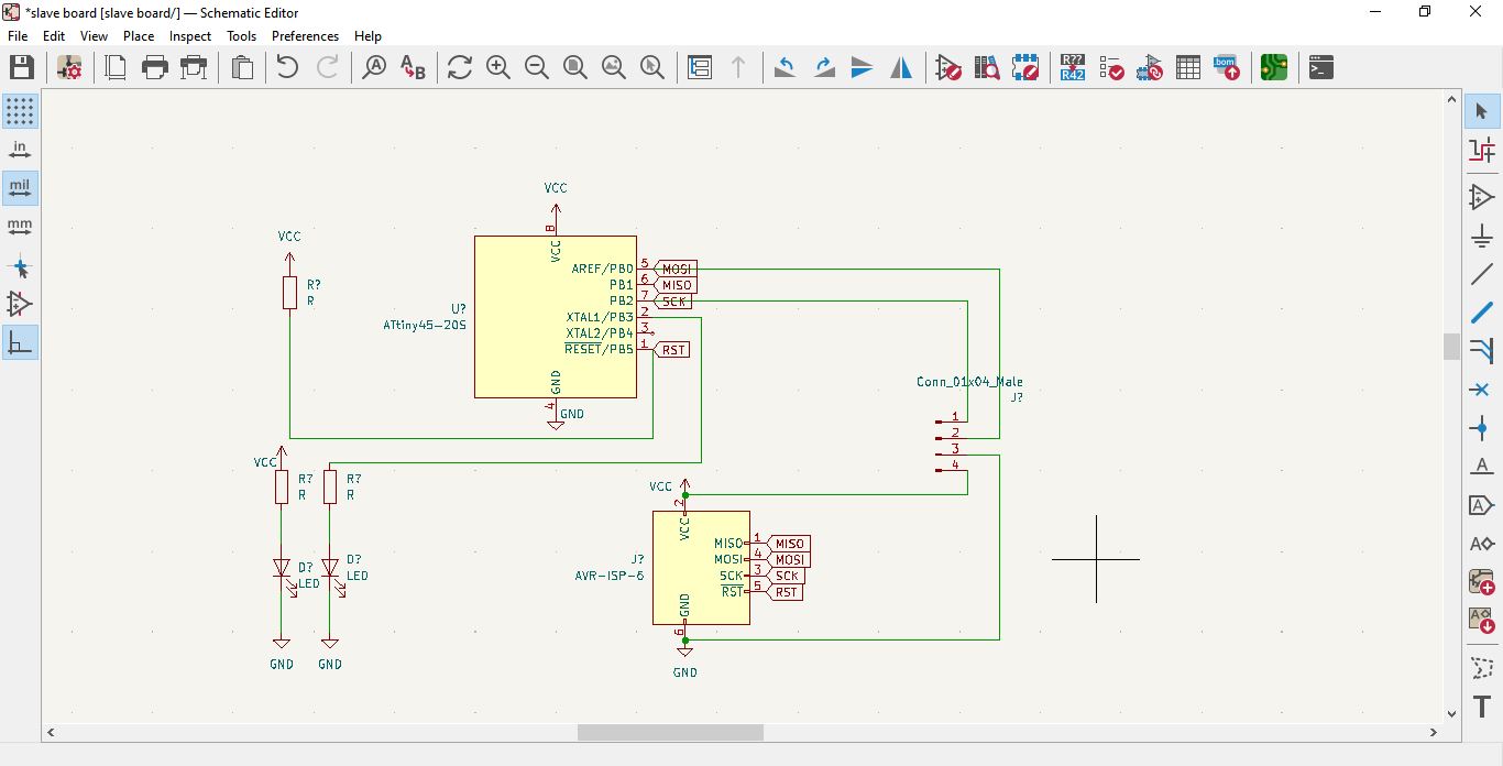 With PCB i have to make plot to produce F.CU svg and Edge cuts files.
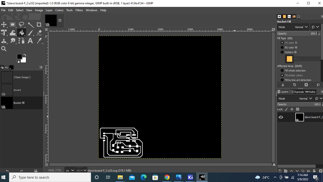
Below, is F.CU image in Gimp to produce F.CU PNG to export in mods.
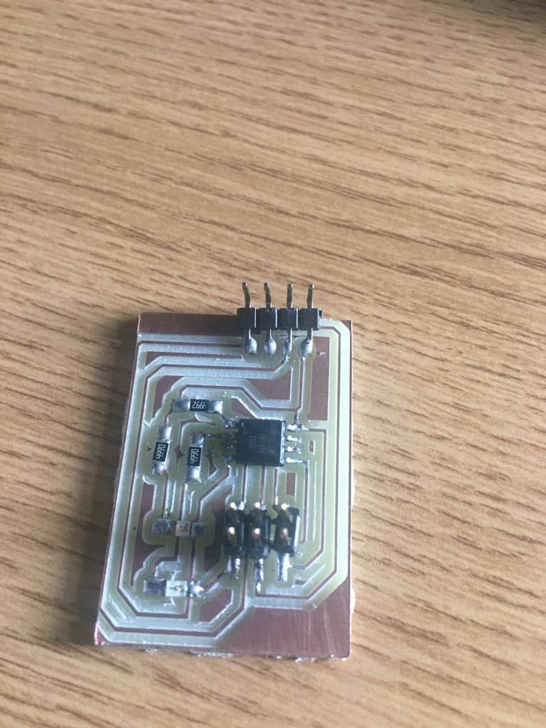
Below is my slave board with solidered components.
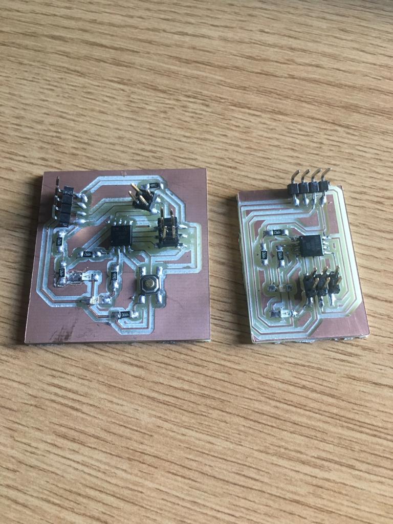
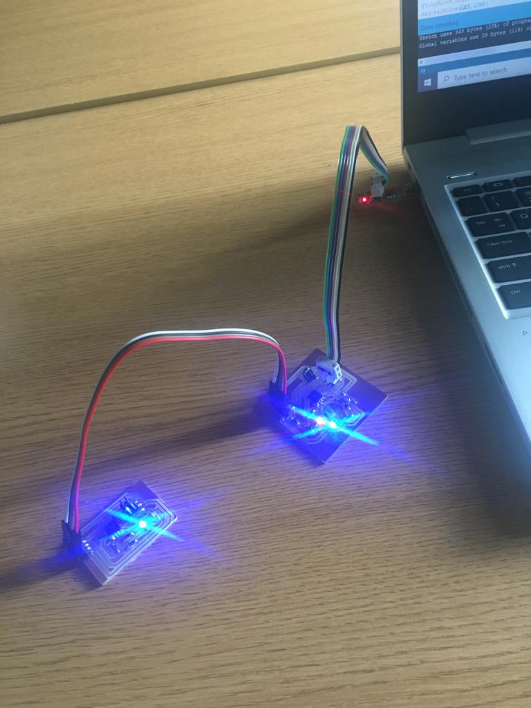
Below is my master board and slave board with solidered components.
Below is code Arduino for master board.
#include<TinyWireM.h>
#define device (1)
#define BTN 4
#define LED 3


void setup() {
  pinMode(BTN,INPUT);
  pinMode(LED,OUTPUT);
  TinyWireM.begin();

}

void loop() {
 TinyWireM.beginTransmission(device);

 int val = analogRead(BTN);
 if(BTN>0)
{

  TinyWireM.beginTransmission(device);
  digitalWrite(LED,HIGH);
  TinyWireM.send(1);
  TinyWireM.endTransmission();
}
else
{TinyWireM.beginTransmission(device);
digitalWrite(LED,LOW);
TinyWireM.send(0);
TinyWireM.endTransmission();
}
}
Below is code Arduino for slave board.
#include<TinyWireS.h>
#define LED 3
#define I2C_SLAVE_ADDR (1)
int data;

void setup() {
 TinyWireS.begin(I2C_SLAVE_ADDR);
 pinMode(LED,OUTPUT);
}

void loop() {
  if (TinyWireS.available())
  byte data = TinyWireS.receive();
  if (data == 1)
  digitalWrite(LED, HIGH);
  else if (data == 0)
    digitalWrite(LED, LOW);

}
I uploaded the code to the master and slave boards. when i powered the board to by using the FabISP, i donot get the out put on the slave board but the master board is working fine. i went through code again and it is fine. Then i checked the wiring of i2c bus, i was wrongly wired the i2c bus each other. i corrected them and i powered it again and find its working.
Download file ` Networking and comunication