5. Electronics production
Assignment
Group assignment
.Chracterize the design rules for your in house PCB production process.
.Extra credit: send a PCB out to a board house
Individual assignment:make an in-circuit programmer that includes a microcontroller.
-Extra credit:customize the design
-mill and stuff the PCB
-test it to verify that it works
Group Assignment
After having adjusted the milling tip, we go to the web to download the images of the plate that i want to manufacture. you can access the instructions by clicking here
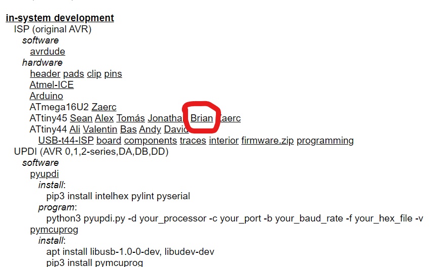
1.Go to Build the FabTinyISP i have used example of student Brian
2.Download the rml and PNG files for the traces and the board outline.
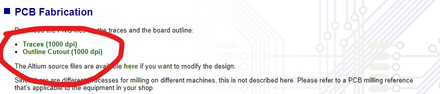
.traces
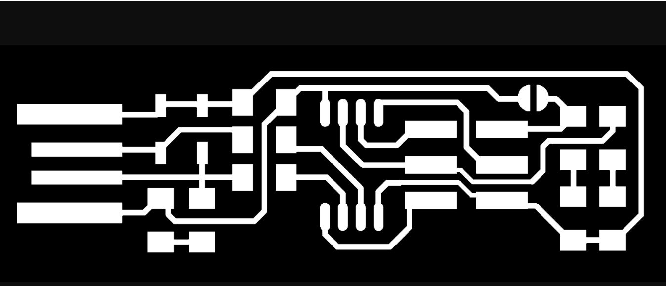
.Outline

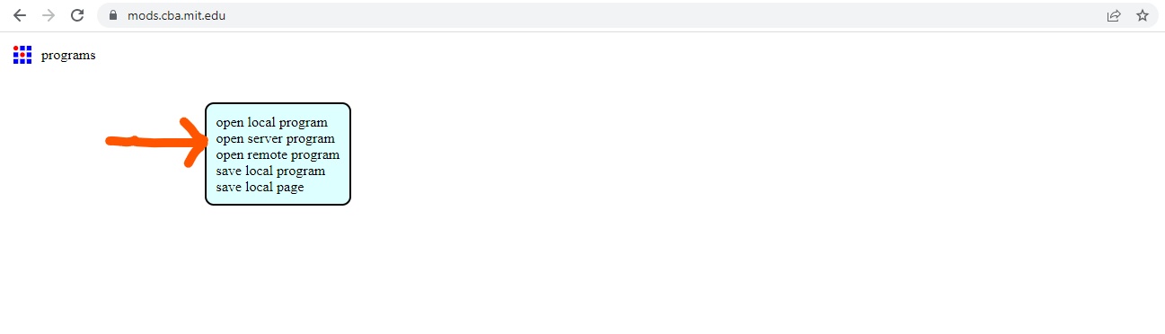
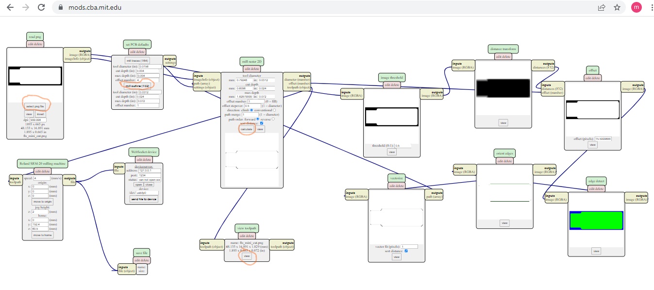
3.Go to the software of mods.
4.Right click>programs
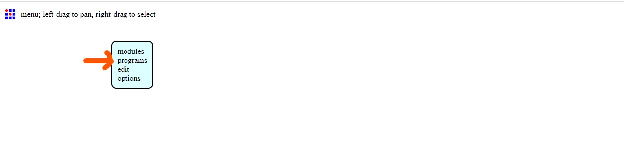
5.Right click>open server program
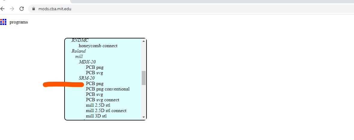
6.Roland>mill>SRM-20>PCB.png
7.Select Websocket Device, and delete by clicking on inputs and outputs until red line disappears.choose delete.
8.Right click>select new server program>Roland>SRM-20>PCB png this will generate the nodes related to our machine, next we add a node that allows us to download the output file, rightclick>new server module>file>save
9.On the PNG module select the Traces > on the PCB Default module select mill traces(1/64)>Connect to be able to save on the mill Raster select calculate,now the browser should download the RML
-Load file
-select bit size
-set to zero
-Add to save node to download RML
-Calculate
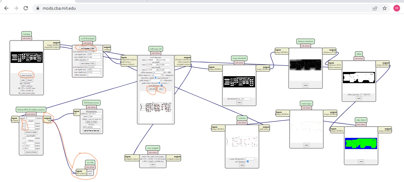
10.Repeat the same steps for the outlines by selecting the outlines PNG,select the mill outline (1/32)option and on the mill Raster node calculate.
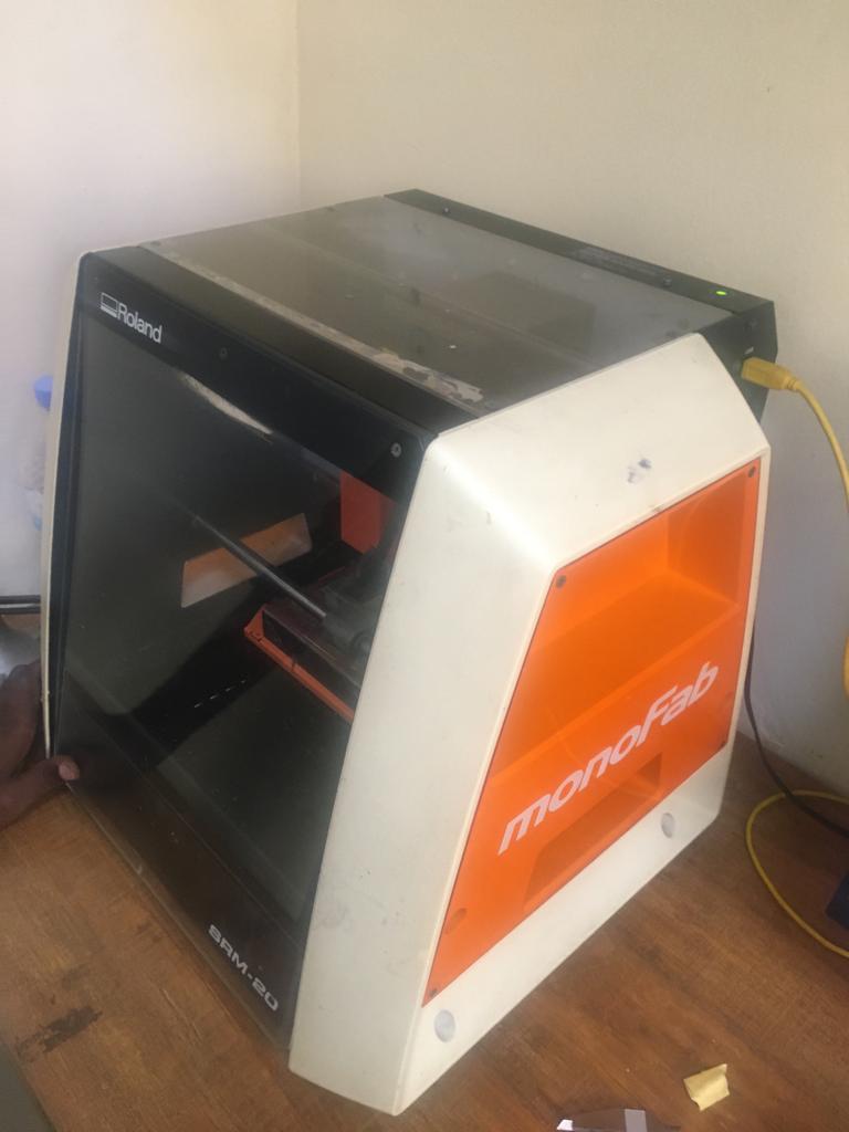
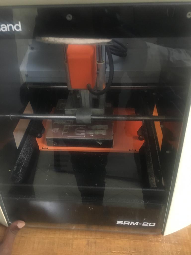
The machine i used is Roland SRM-20
*Individual assignment*:
make an in-circuit programmer that includes a microcontroller.
-Extra credit:customize the design
-mill and stuff the PCB
-test it to verify that it works
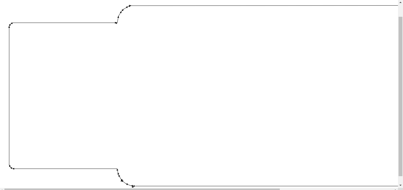
Here is the process we went through to cut and mill the board:
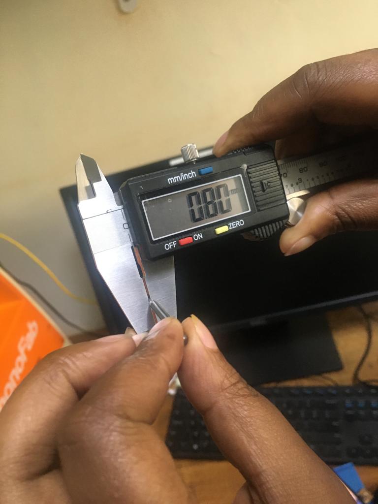
The mill bits used (1/64) is the smaller one used for trces it has diameter 0.4mm, (1/32) is the larger one used for outlines it has diameter of 0.8mm
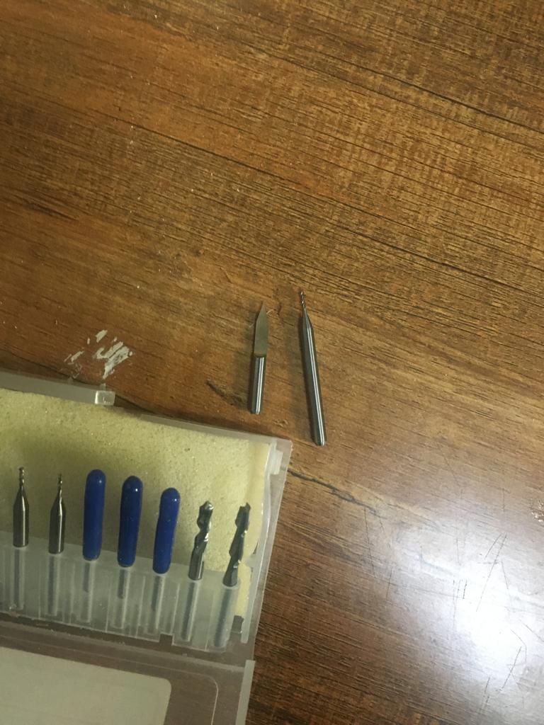
i have used vaniacalliper to measure diameter of cut outline
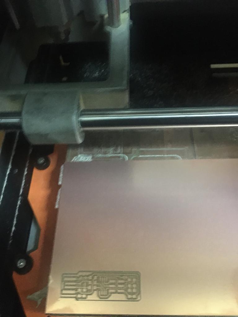
After converting the images the next is printing board you have to switch your file to VPanel for SRM-20 software to communicate with the milling machine.
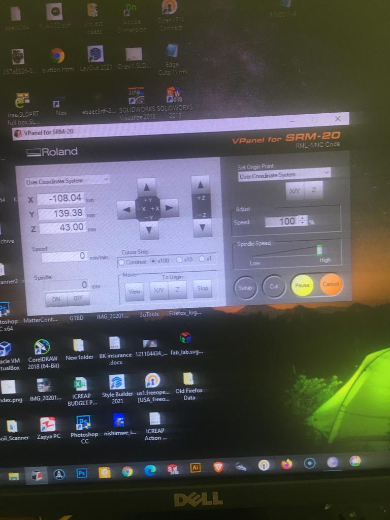
Now i fixed the board on the bed, i am ready start milling
 mistakes i made, and how i resolved them
I didn’t fix well board when machine starts milling the board changes position
to collect mistake i fixed the board with tape
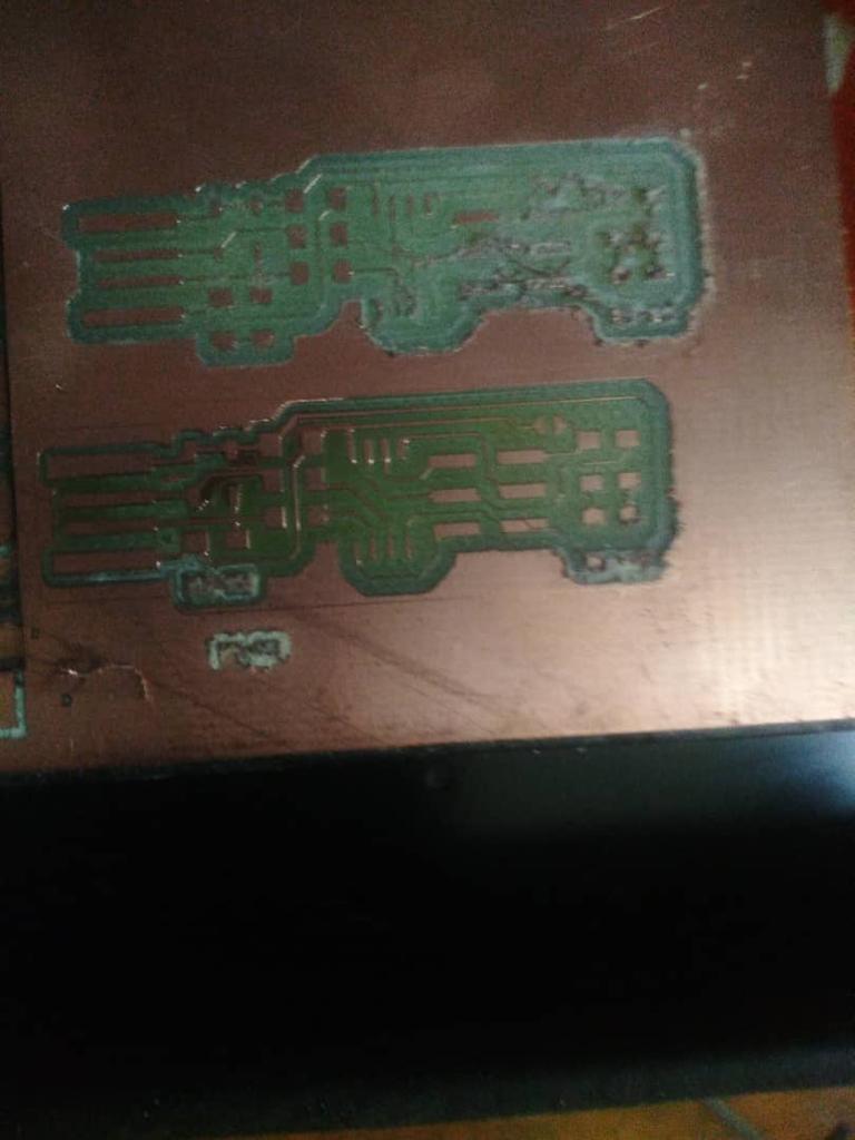
Inspect that the board is clean and well fix, the millbits used here and the precalibrated settings on the MODS for RMS-20 produced excellent results.
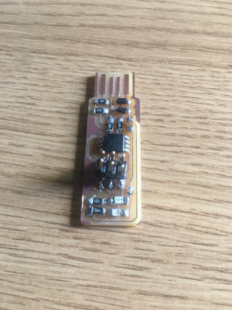
use sharp tool to peel away the excess coper on the usb pads.
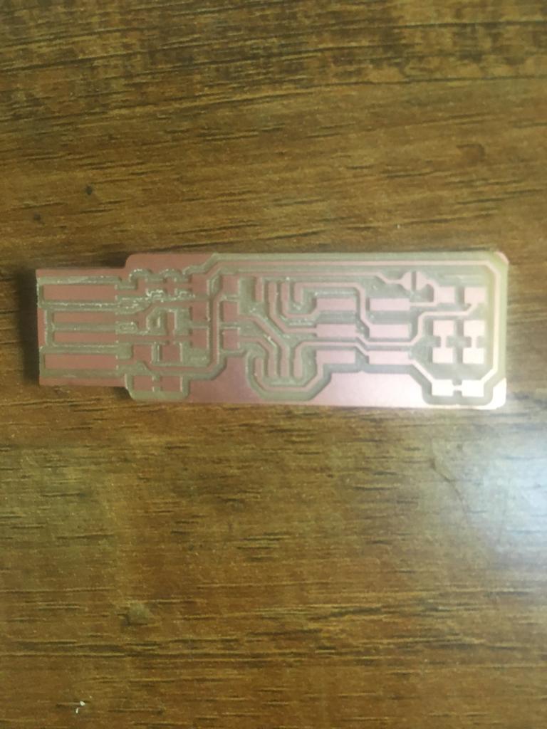
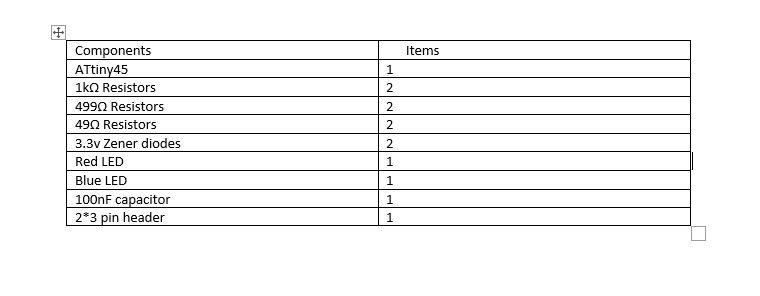
Components to be used
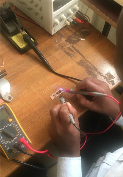
i have made solidering to PCB
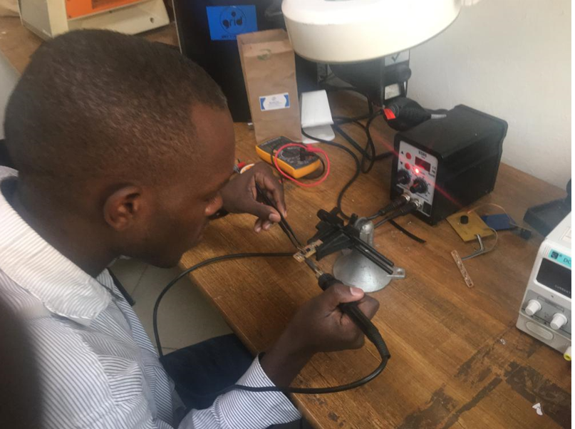
I have to test continuity using multimeter
Programming the programmer
First i downloaded the firmware to be loaded in the programmer.
-Run make flash in terminal to program the its flash memory.
-Run make fuses to set up all fuses except one that disables the rest pin.
-Blowing the reset pin, I have to type rstdisbl.
For this process the USBtiny was ready to be a programmer.
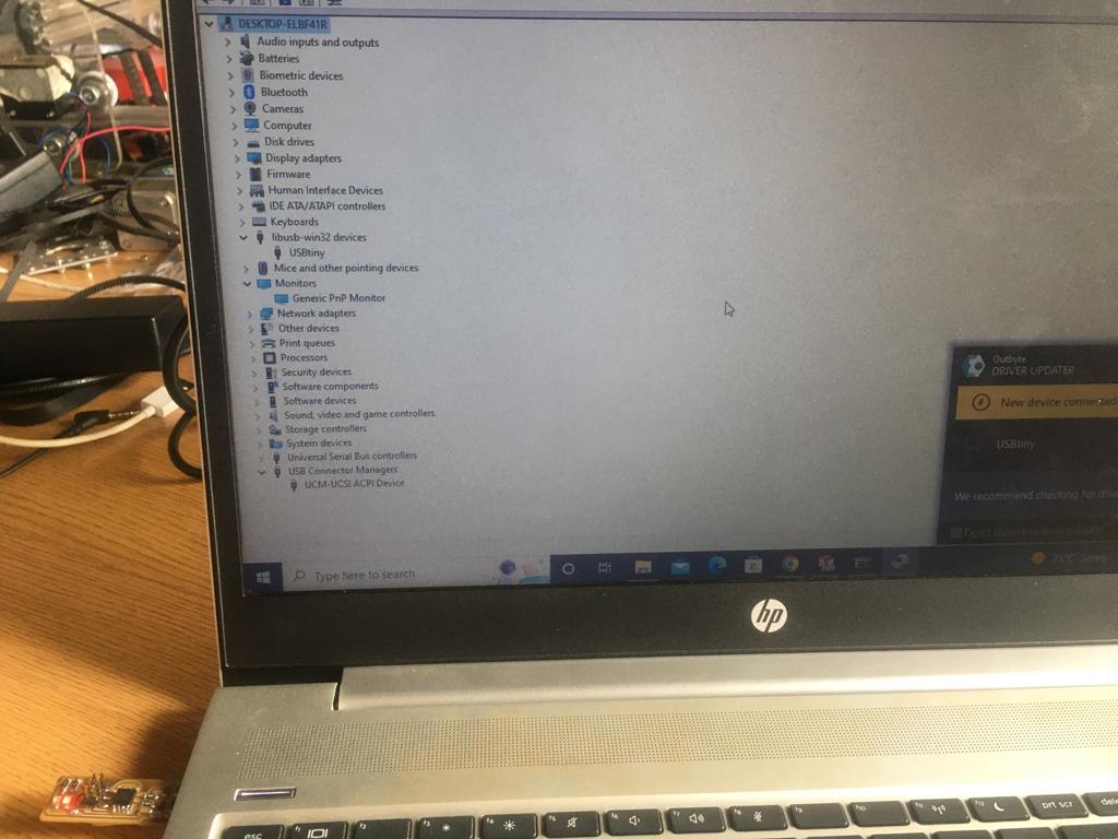
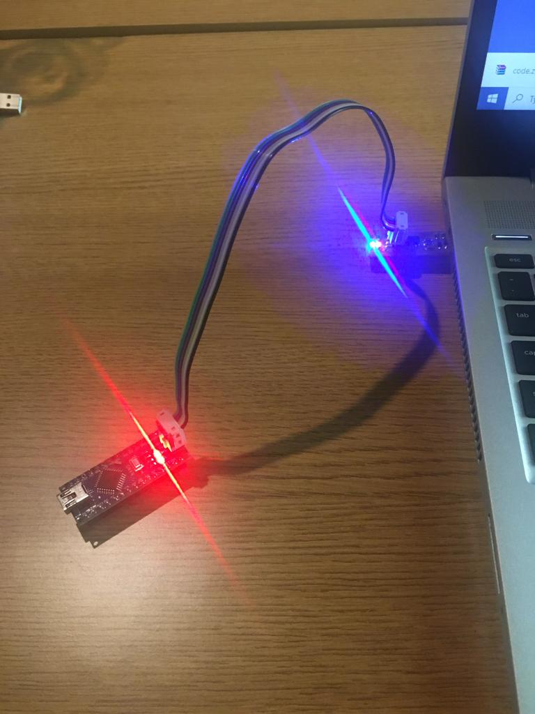
Below, testing programmer its fully working i programmed NANO Arduino.
MY FILES
Here i am uploading the files that i have been making.