11. Input devices
Assignment
Individual assignment: Measure something add a sensor to a microcontroller board that you have designed and read it.
Group assignment: Measure the analog levels and digital signals in an input device.
What i did
. Define a sensor.
. Designed a board with a phototransistor in KiCAD
. Milled and soldered the components.
. programmed the board.
A sensor: is a device that detects the change in the environment and responds to some output on the other system. A sensor converts a physical phenomenon into a measurable analog voltage(or sometimes a digital signal)converted into a human-readable display or transmitted for reading of further processing.
Types of sensors
.Temperature sensor.
.Proximity sensor.
.Acceleroter.
.IR sensor(Infrared sensor).
.Pressure sensor.
.Light sensor.
.Ultrasonic sensor.
.Smoke,Gas and Alcohol sensor.
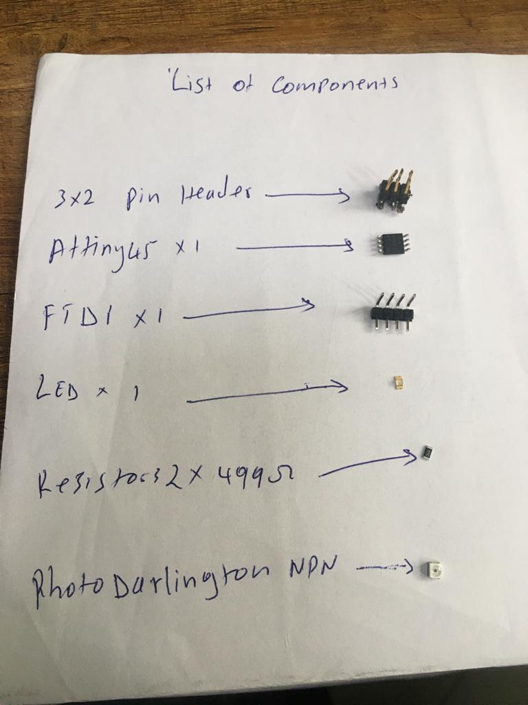
Input devices available in fablab are temperature sensor,light sensor,ultrasonic.I decided to light sensor which is photo darlington NPN for input assignment.
Introduction
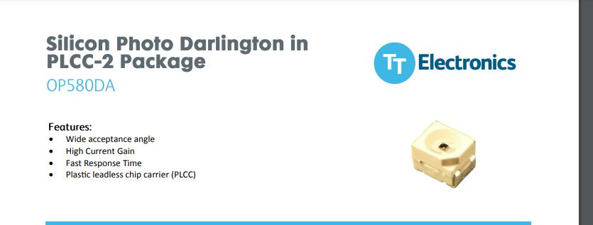
Photo darlington NPN photodetector can be used where high levele are gain neededin a light sensor or detector.the photodarlington is able to provide much higher levels of sensitivity.
Below is picture of photodarlington and its features.
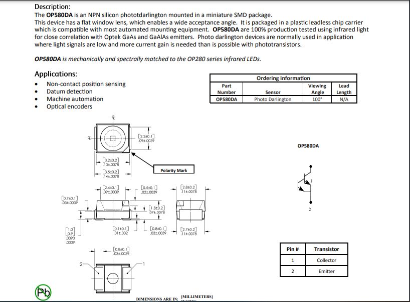
Below is datasheet connection of pins and description of photodarlington transistor.
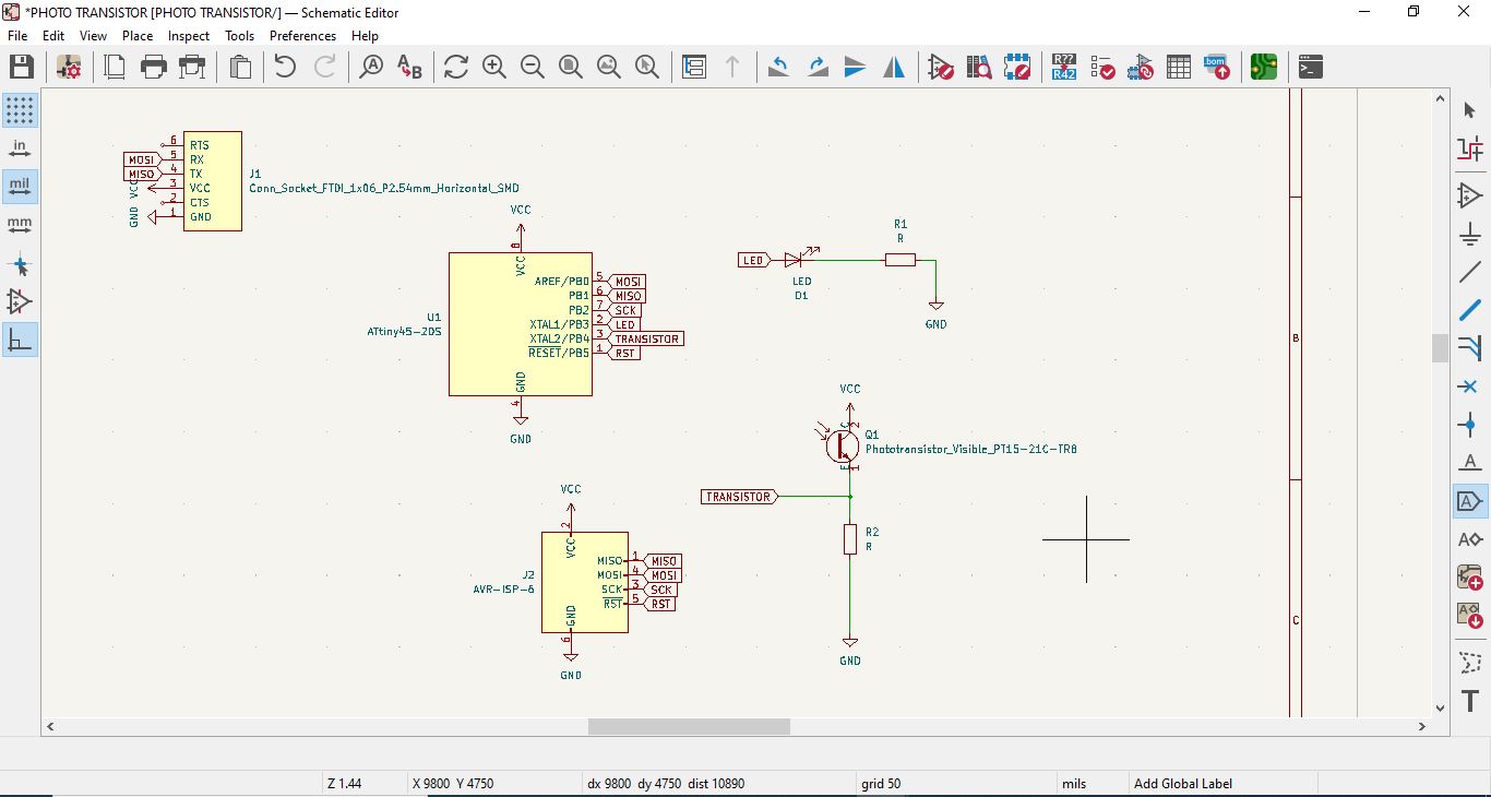
I made design in which an LED is activated by the Photodarlington PNP.The values are set in the programming for the LED to active and deactive. i used KiCAD to design. Below is the schematic Editor of the circuit.
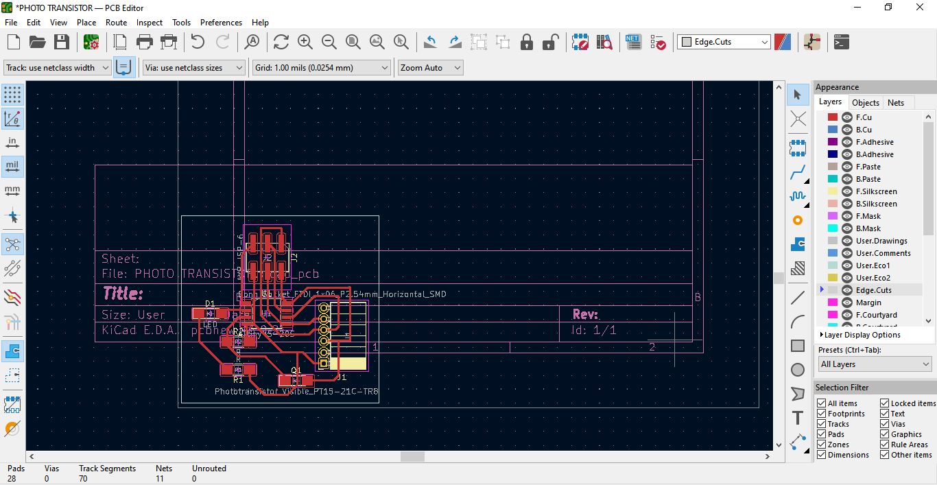
Below, is schematic whch switched to PCB Editor.
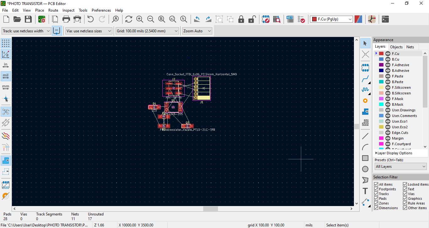
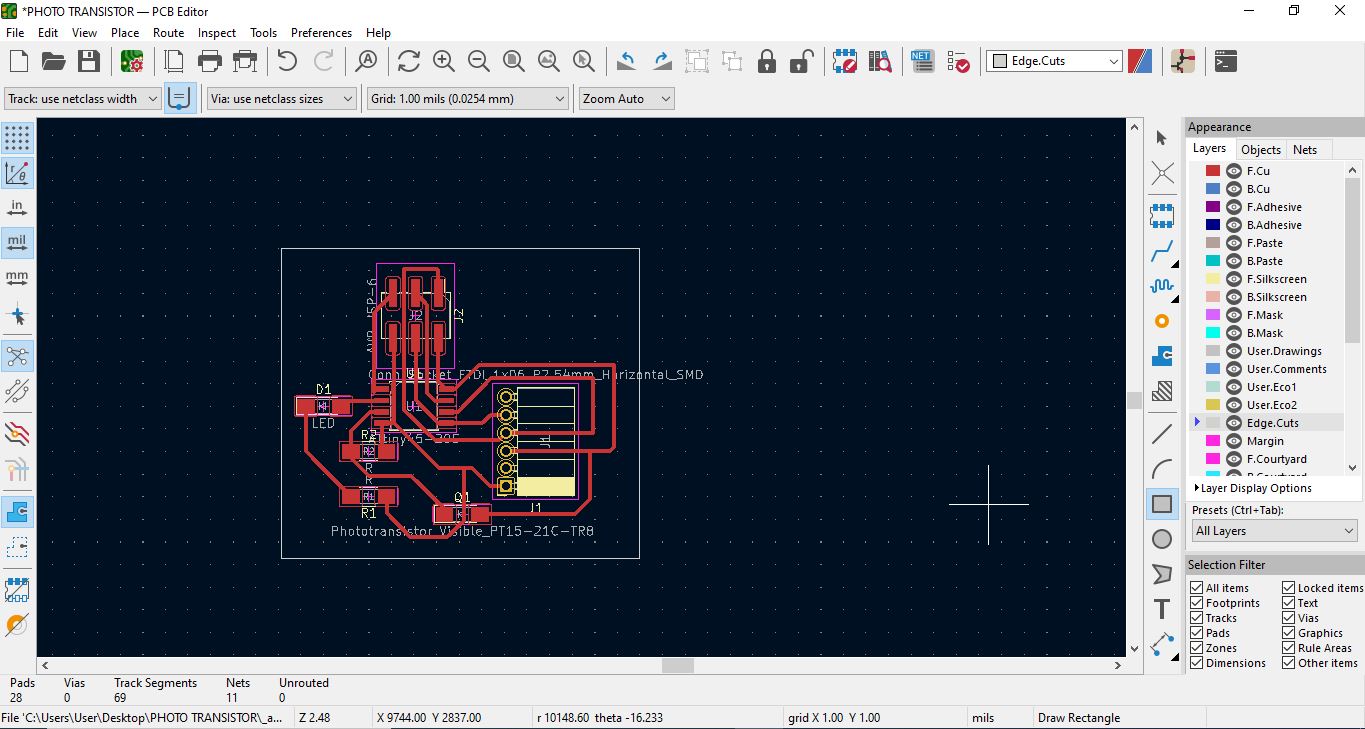
Below is PCB made of Route tracks and edgecuts.
Below with PCB i have to plot it and produce F.CU svg and Edge cuts files.
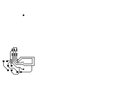
Below is my F.CU mill image in svg file to export to Gimp.
Below is my Edge Cuts image in svg file to export to Gimp.

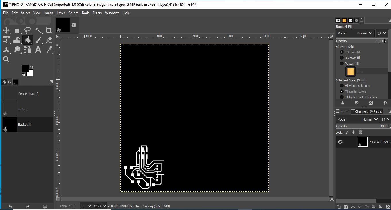
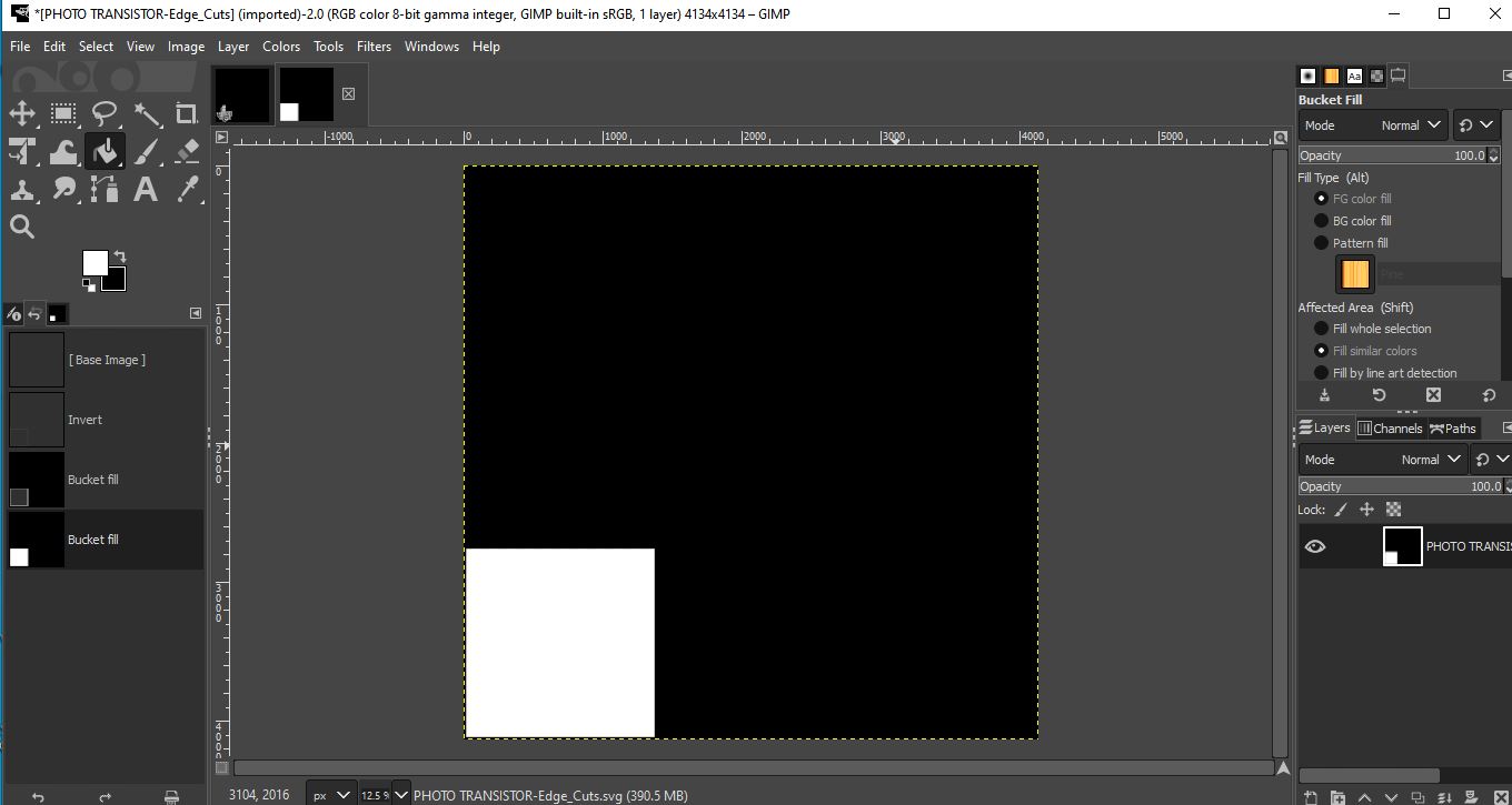
Below is my F.CU image in Gimp to produce F.CU PNG to export in mods.
Below is my Edge cut image in Gimp to produce F.CU PNG to export in mods.
The components were soldered correctly.
After i have pass my F.CU PNG and Edge cuts PNG in mods to abtain rml files and send them to Roland machine to print my PCB. I made it and start solidering with components.
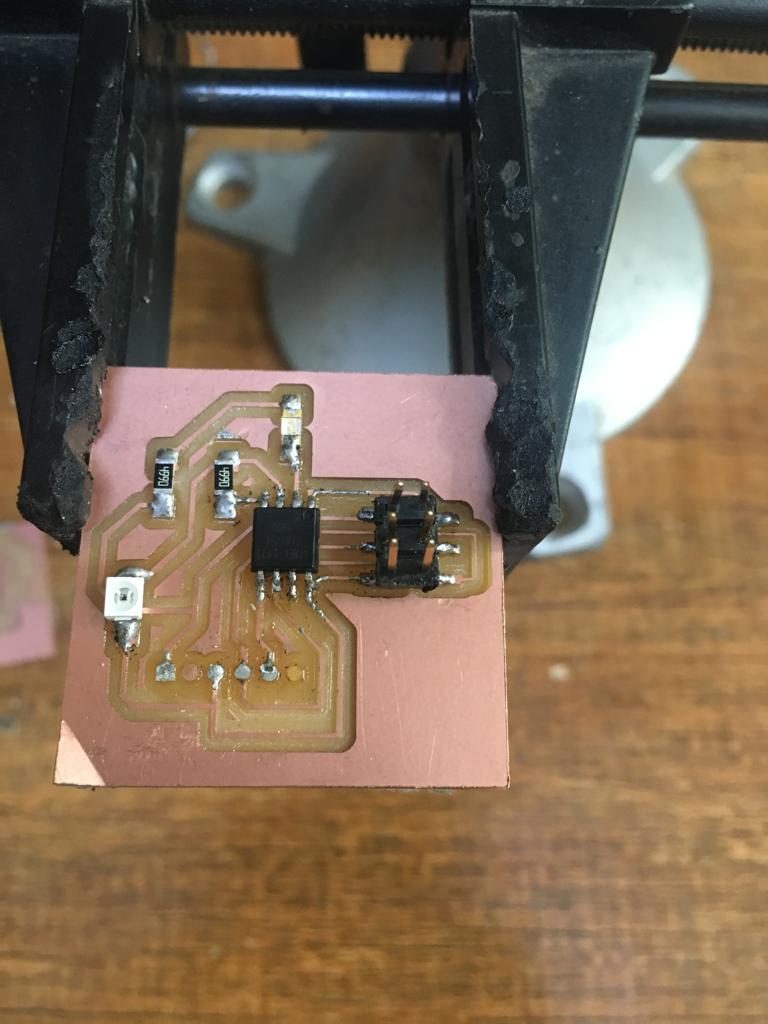
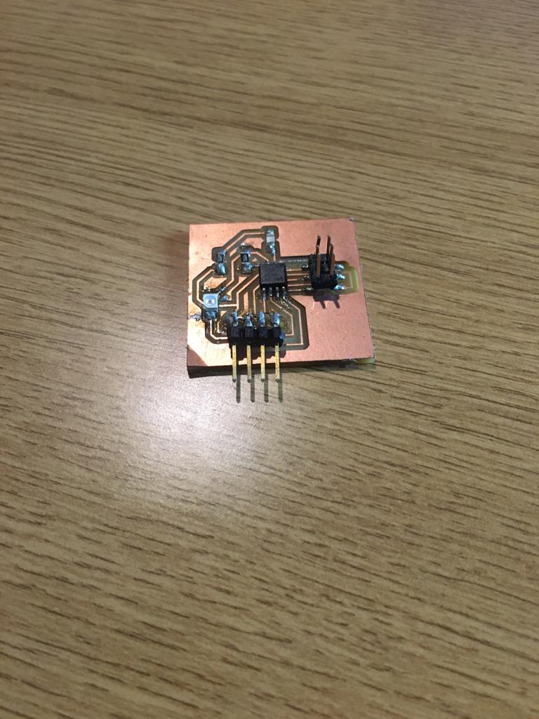
Below is my final Board with solidered components.
I used ATtiny45 for this board. The pinout diagram is below.
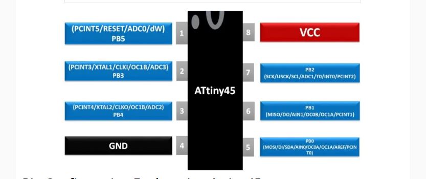
I used Arduino to progrm the board. The pins were set the programming was done as follows
#include<SoftwareSerial.h>
SoftwareSerial window(0,1);

void setup() {
 window.begin(9600);
 pinMode (PB3,OUTPUT);


}

void loop()
{
int light=analogRead(A2);
window.println(light);
if(light <=20)
{
digitalWrite(PB3,LOW);
}
else
{
  digitalWrite(PB3,HIGH);

}

}
Final Output
The Photodarlington was working perfectly.The output values were showing on the laptop screen.It was programmed to light up the LED for sensor values above 20 and using hand press near photodarlington LED off for sensor values below 20.
Download files here