8. Computer Controlled Machining
This week I learnt to make the toolpaths and use the CNC machine. The group work is here.
Design
Fusion
The feet
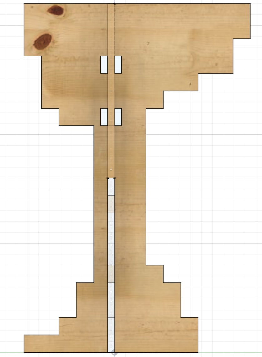
The first step was to create some model, this week required something big and I thought a table wold be a good idea. I wasnred it to look a little Minecraft - ish, and so I used squares to build the base.
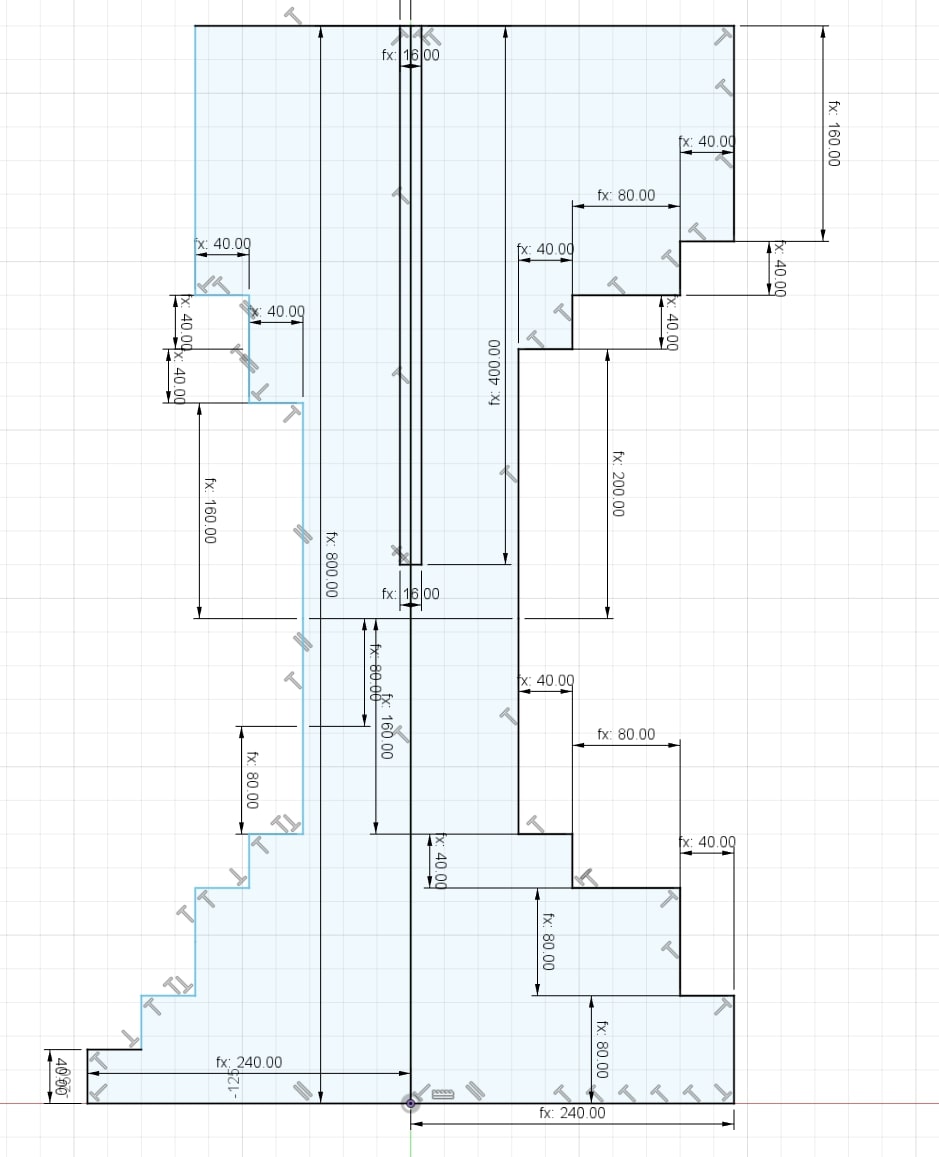
I thought about interlocking both bases in order to give it a little more strength and stability.
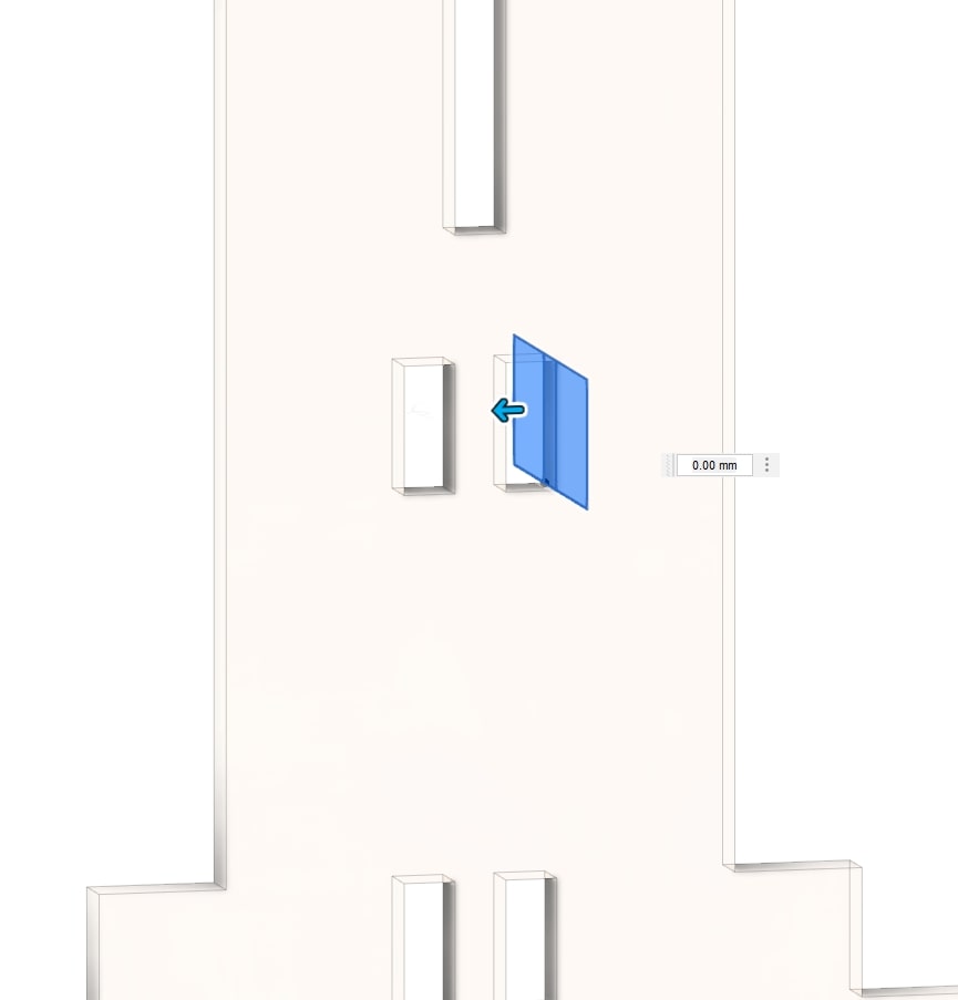
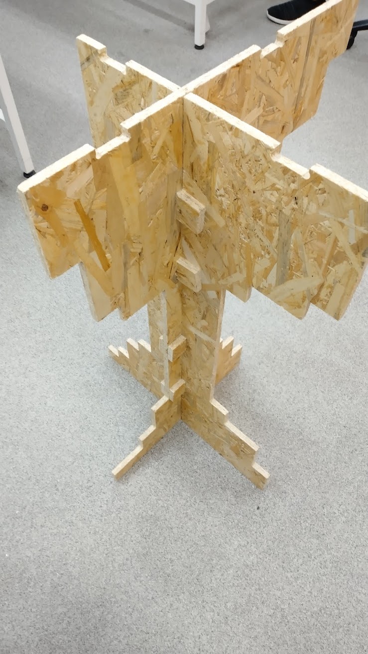
Nevertheless I realized it was going to require a little bit more strengh, or after a while it was going to start bending. I added some small tabs to hold the to pieces in place.
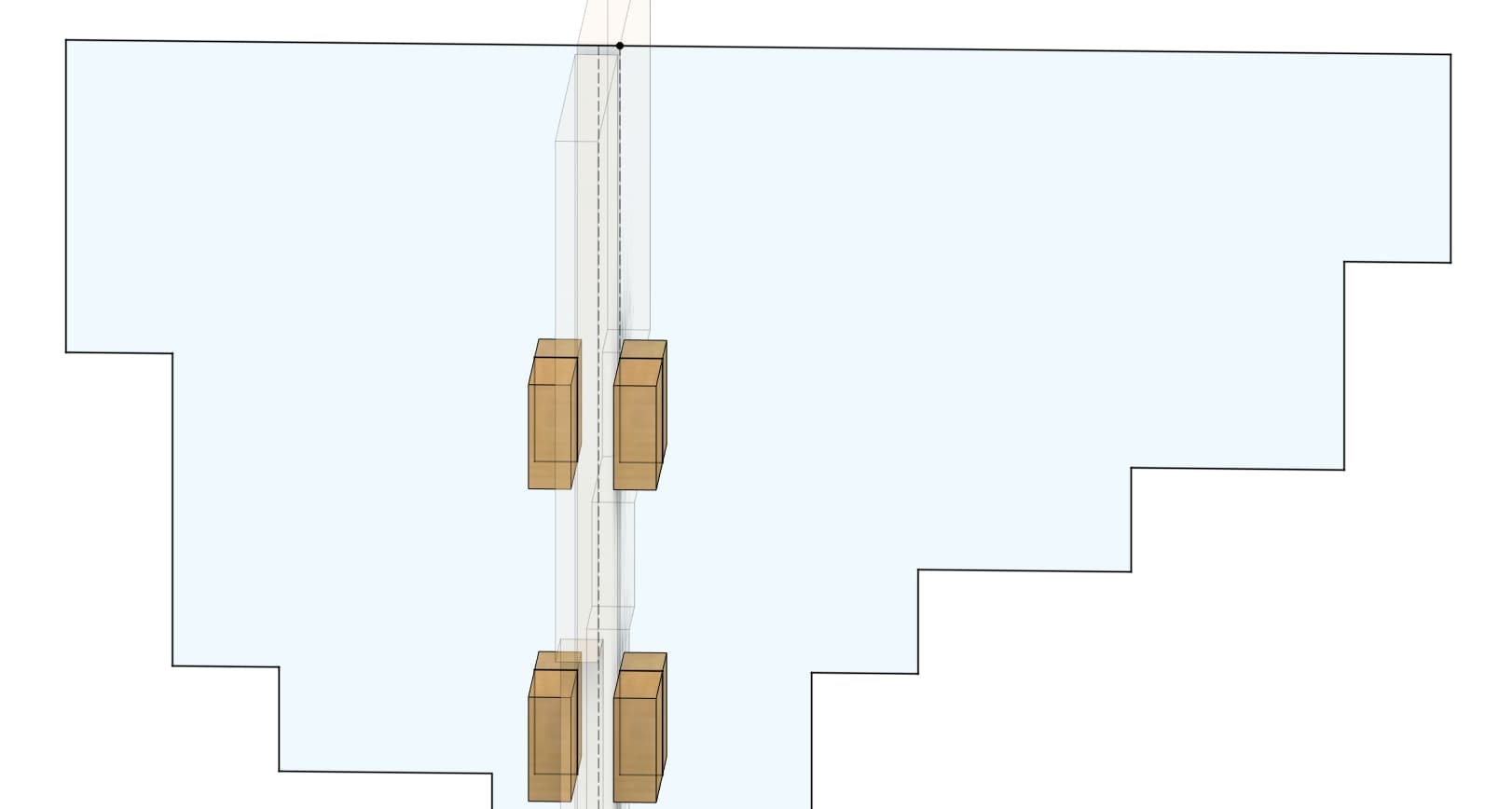
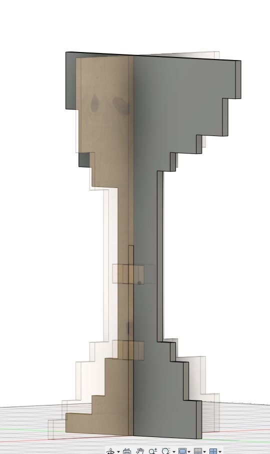
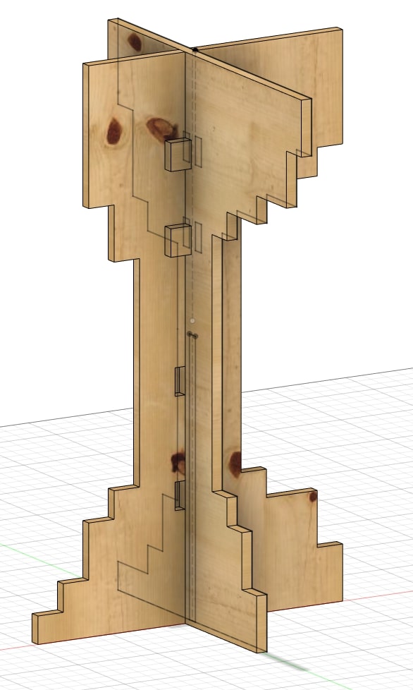
And this is how the two interlocked pieces look like:
The actual table
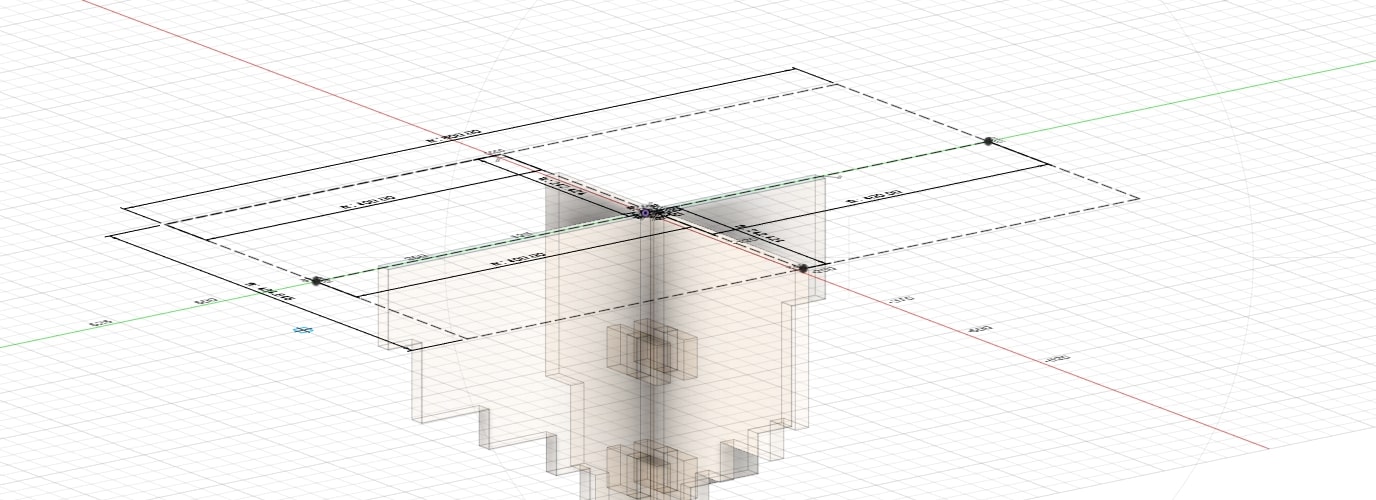
I created a setch on top of the other two pieces. This is going to be the more interesting part of the table.
I thought it would be a coool idea to add an engraving of the wourld on top of the table, and so I dheaded to inkscape and used an image from the internet to make an .svg file I could paste in Fusion 360.
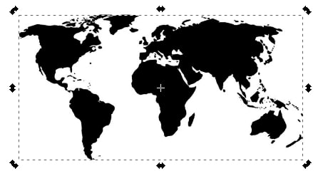
I created a bitmap.
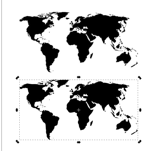
And imported it into Fusion. At first it was a little too small but this was quickly fixed by simply saling it at the moment of importing it.
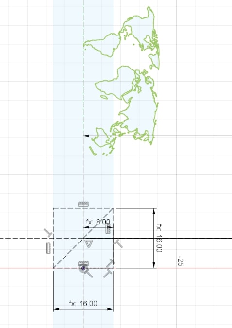
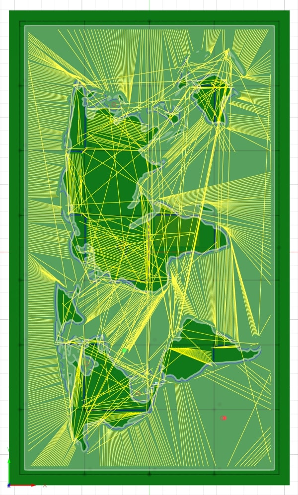
For some reason South America was not reognized as a face and I had to create a countour using the *Spline line.
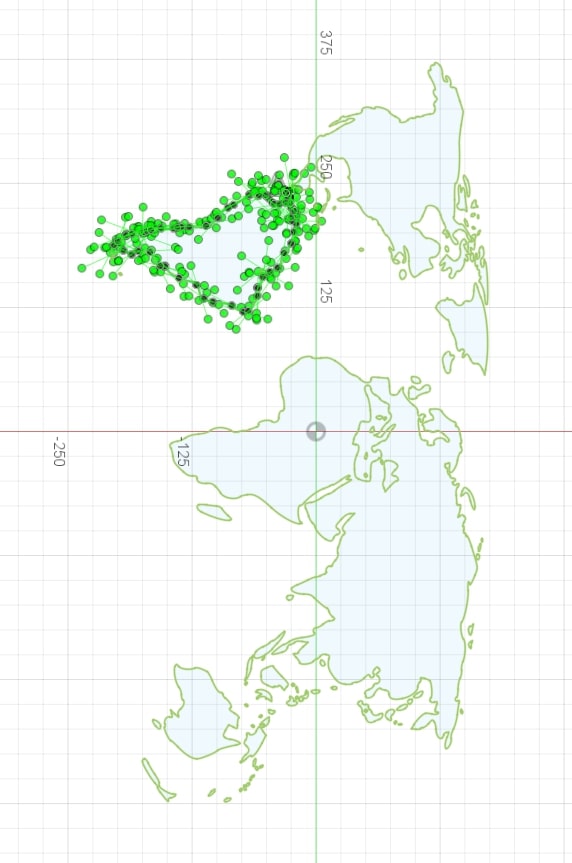
I extruded it.
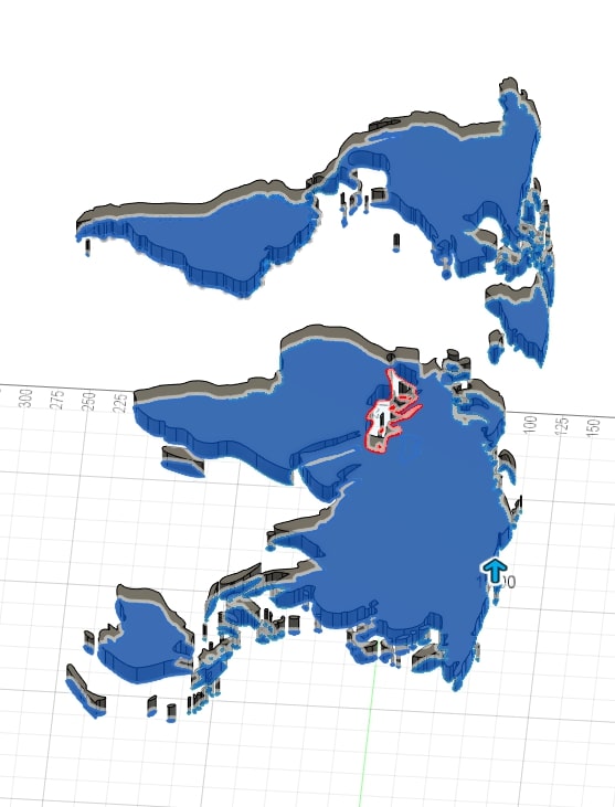
I extruded the base to keep the continents together. In order to keep the Minecraft - ish look I created a grid in the sketch.
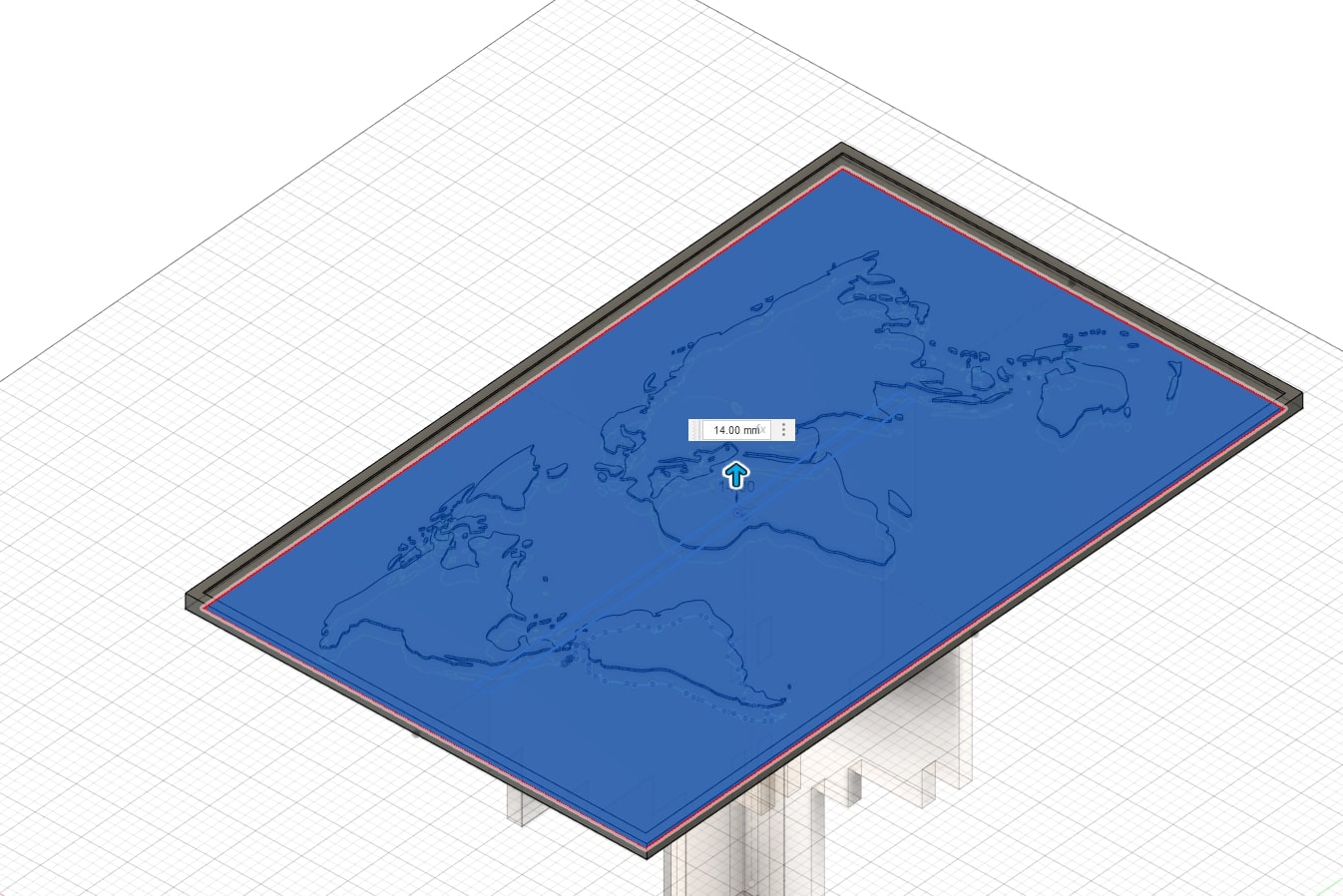
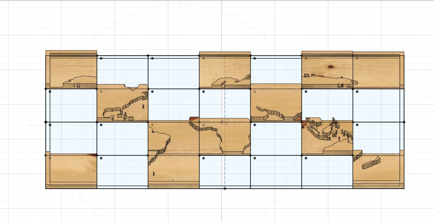
I couldn’t think of a more “elegant” way to do it, so I just copied the world map a couple times and used the Intersection tool when extruding the base multiple times, each time with a different distance. Layer by layer, the result started to look like this:
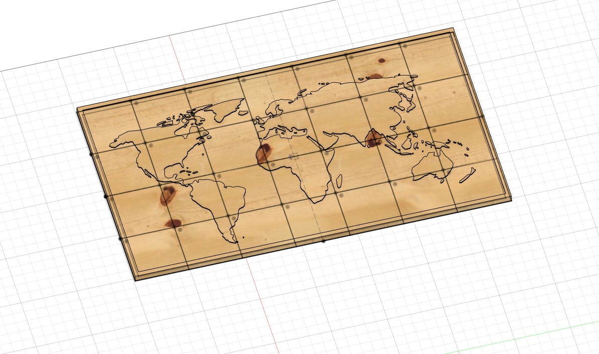
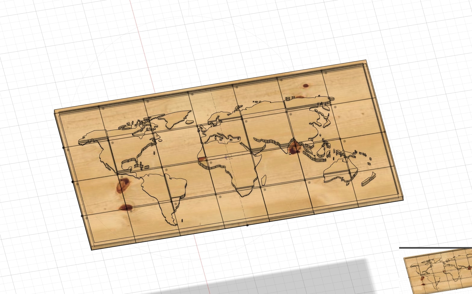
Once finished:
Creating the toolpaths
Adaptive Clearing
I headed to the Manufacturing tab in Fusion and created a SetUp. This step added the stock (the mterial out of which the table will be crated).
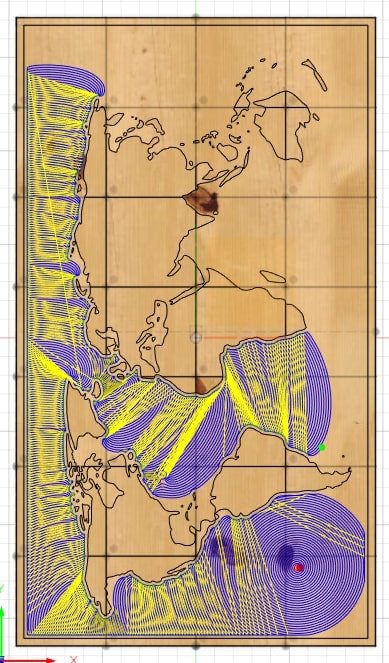
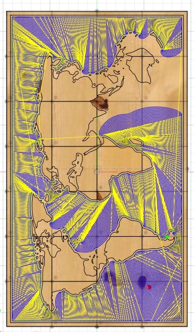
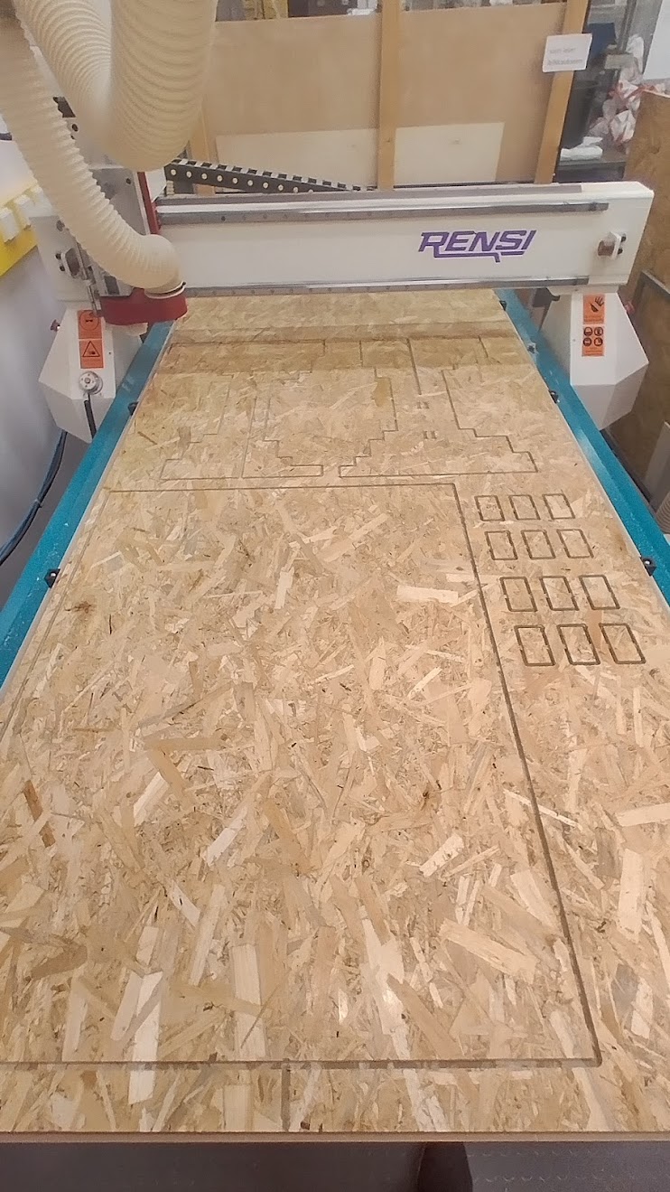
I then selected the Adaptive Clearing function, which creates a toolpath for removing most of the material. It required a tool and I used an *8mm diameter drill bit.

This step took quite a while to get done.

The progress of the calculations could be seen in real time:
And done!
Contour
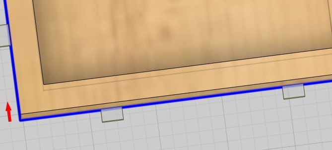
This is so I can remove the shape from the rest of the stock. I was done using pretty much the same step as previously, but now I had to add tabs, this will hold the piece in place and can be easily removed.
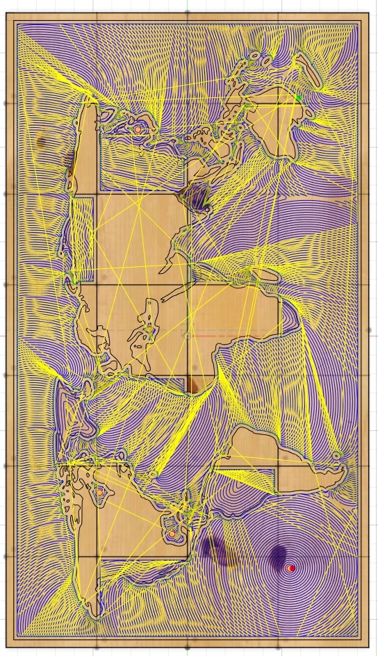
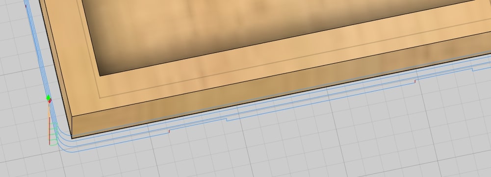
This is how the toolpath looks:
Results
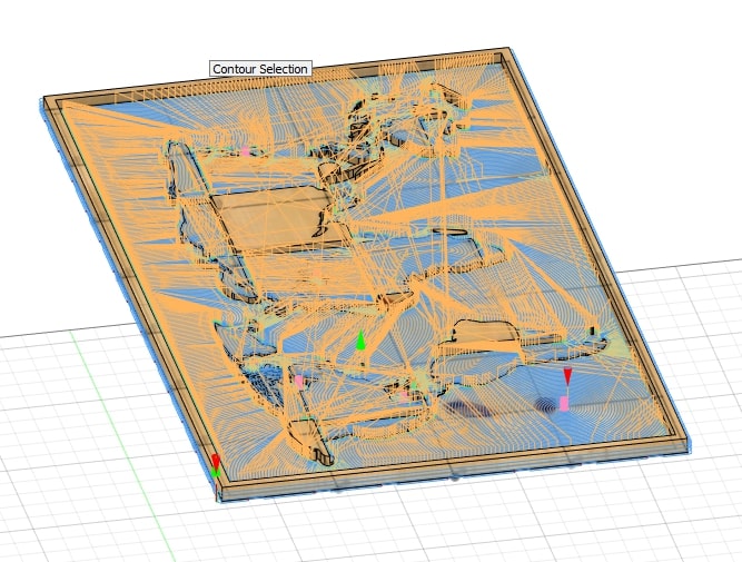
This is how both toolpaths look.
Milling
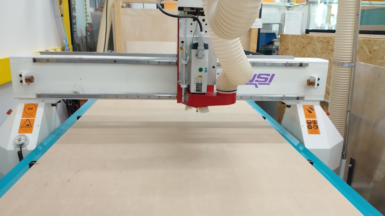
The machine
The group work gives a more detailed description of the process in case of any doubts, you can find it here.
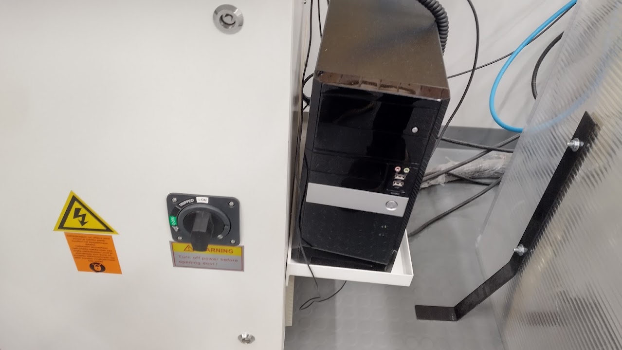
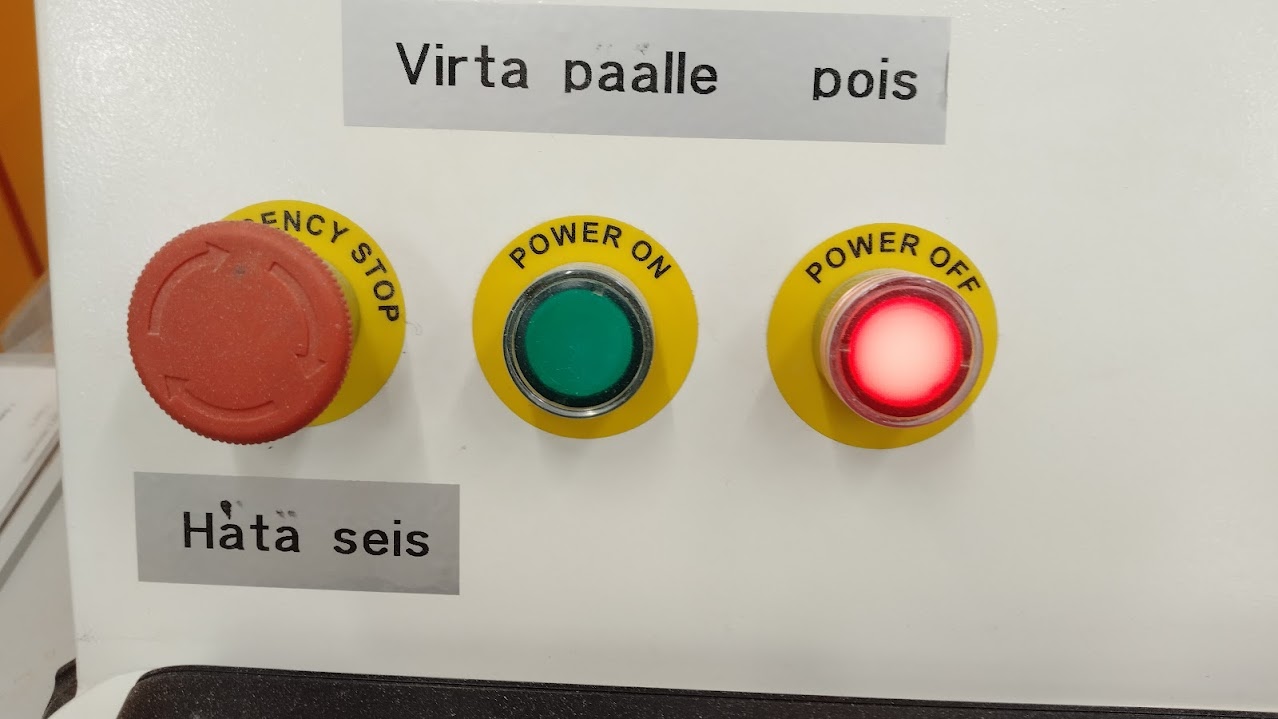
The first step, as always, is to turn un the equipment. In this case the computer must be ppowered before the CNC machine.
Z-axis must be zeroed on top of the vaccuum bed, the vaccuum pumps must be turned on for this. (The board bends under the pressure of the vaccuum).
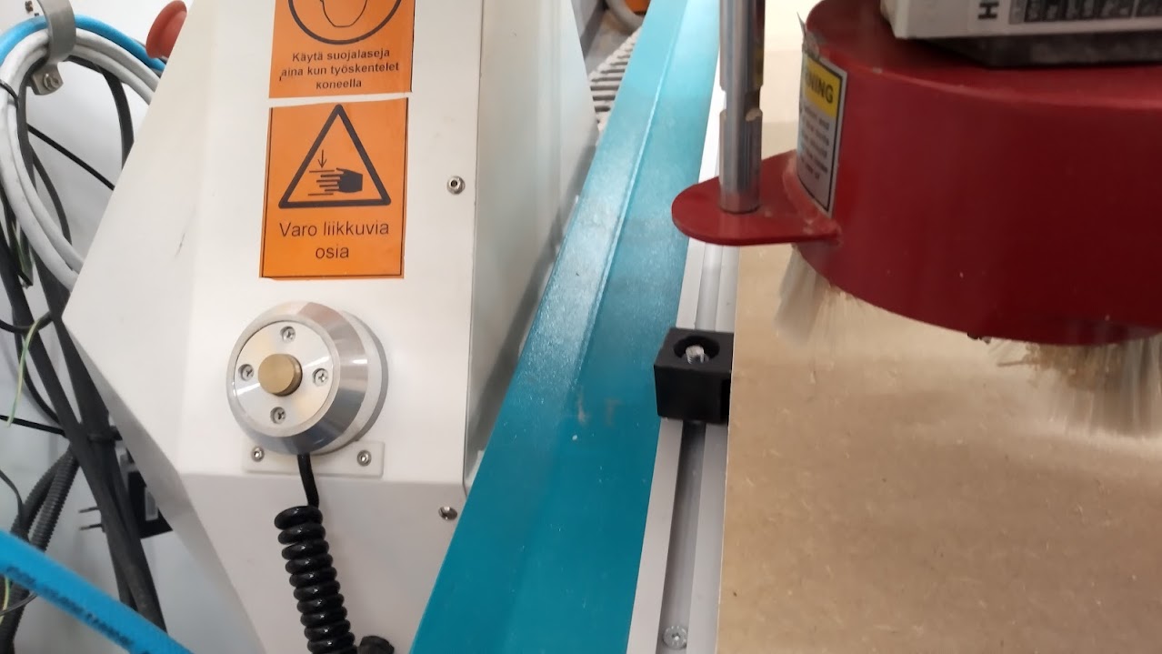
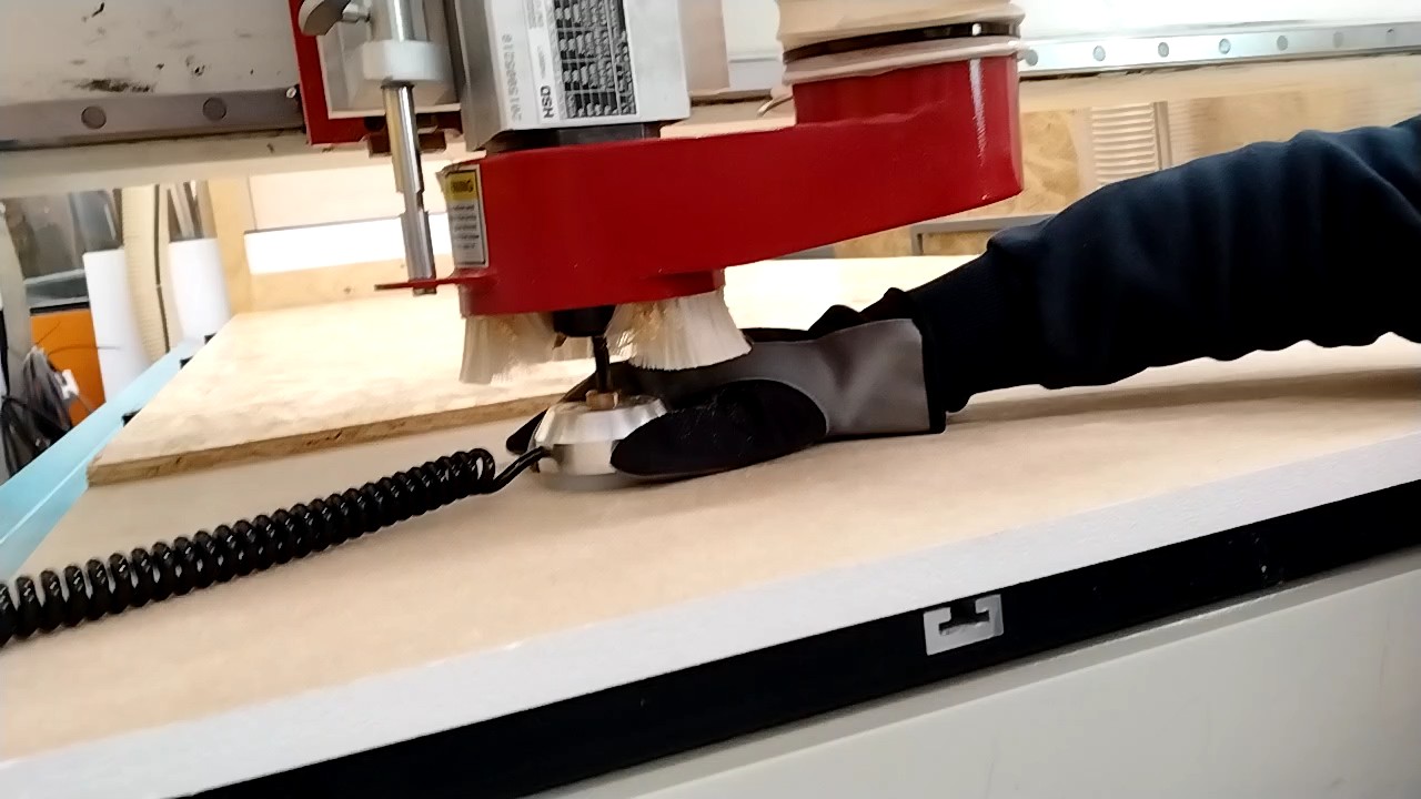
The calibrator must be placed on top of the bed and right below the tool.
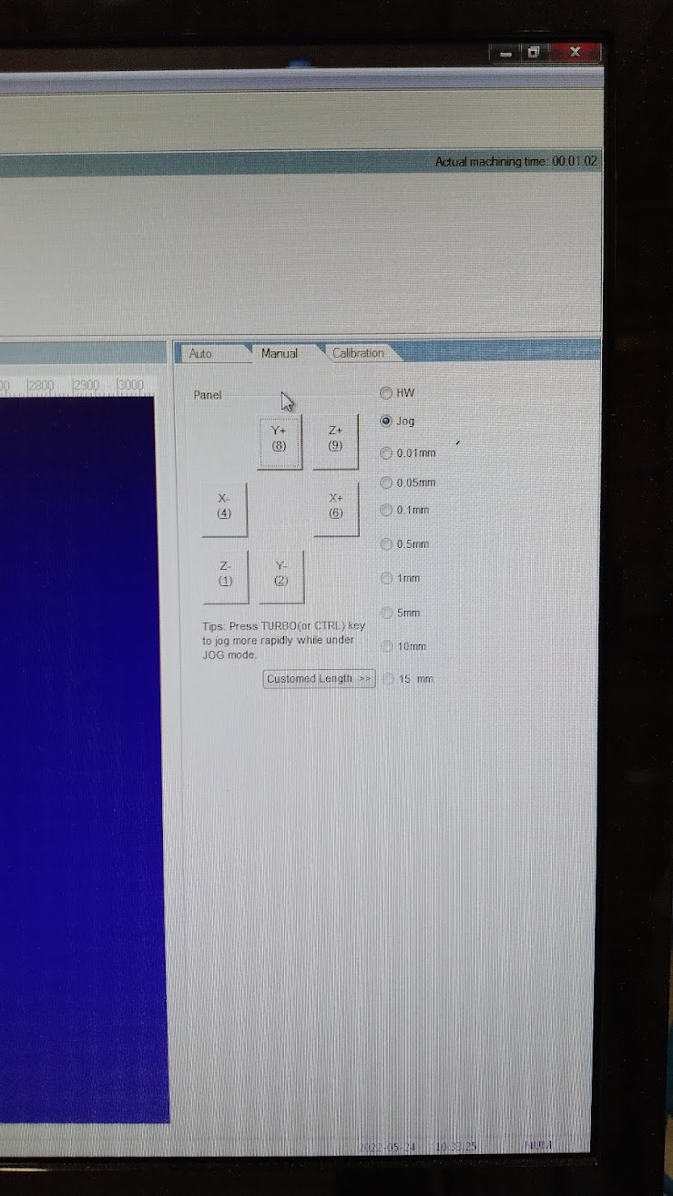
The tool can be moved using the next menu:
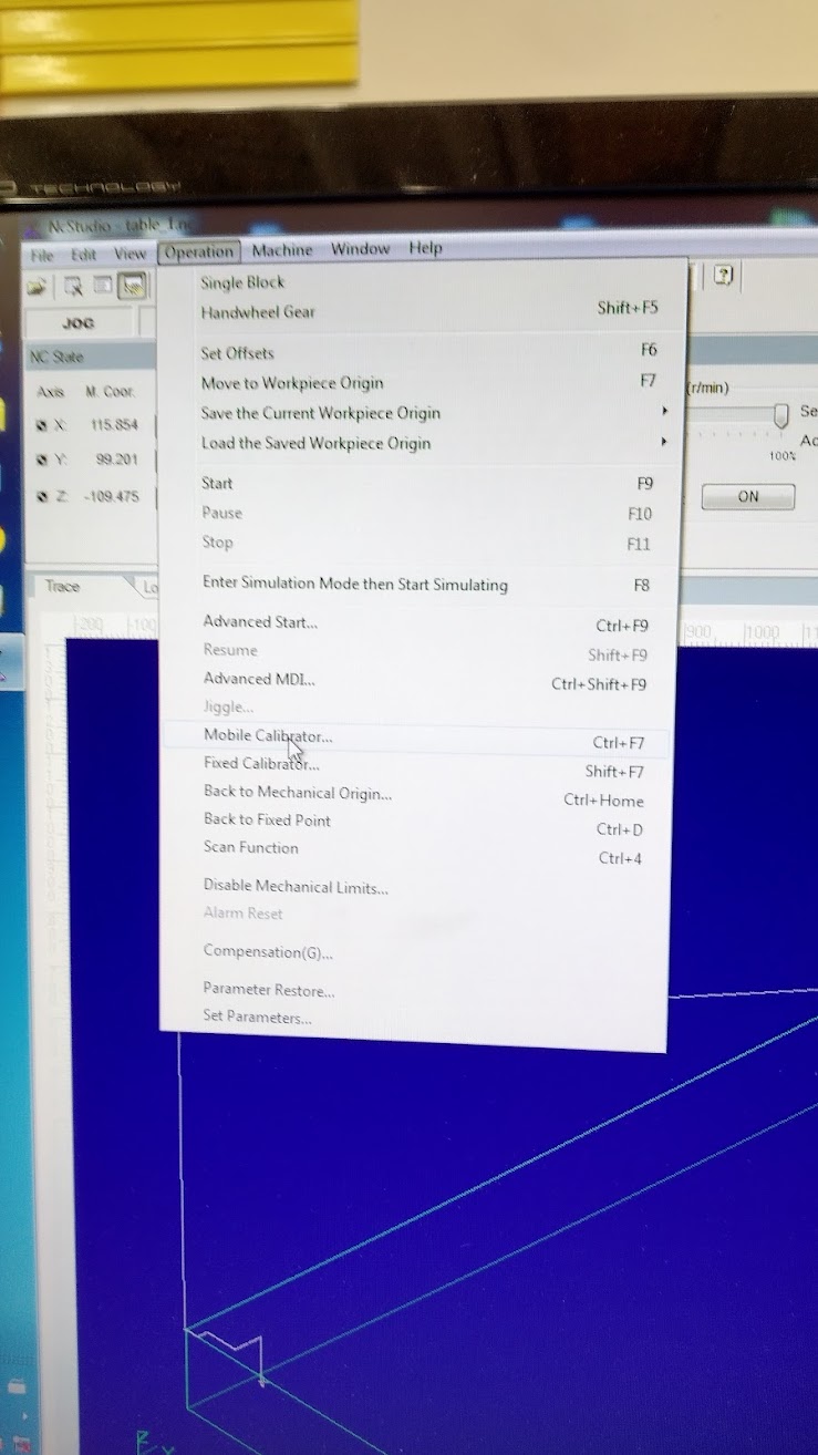
The Z-axis can be autommatically calibrated with the help of Operation > Mobile calibrator.
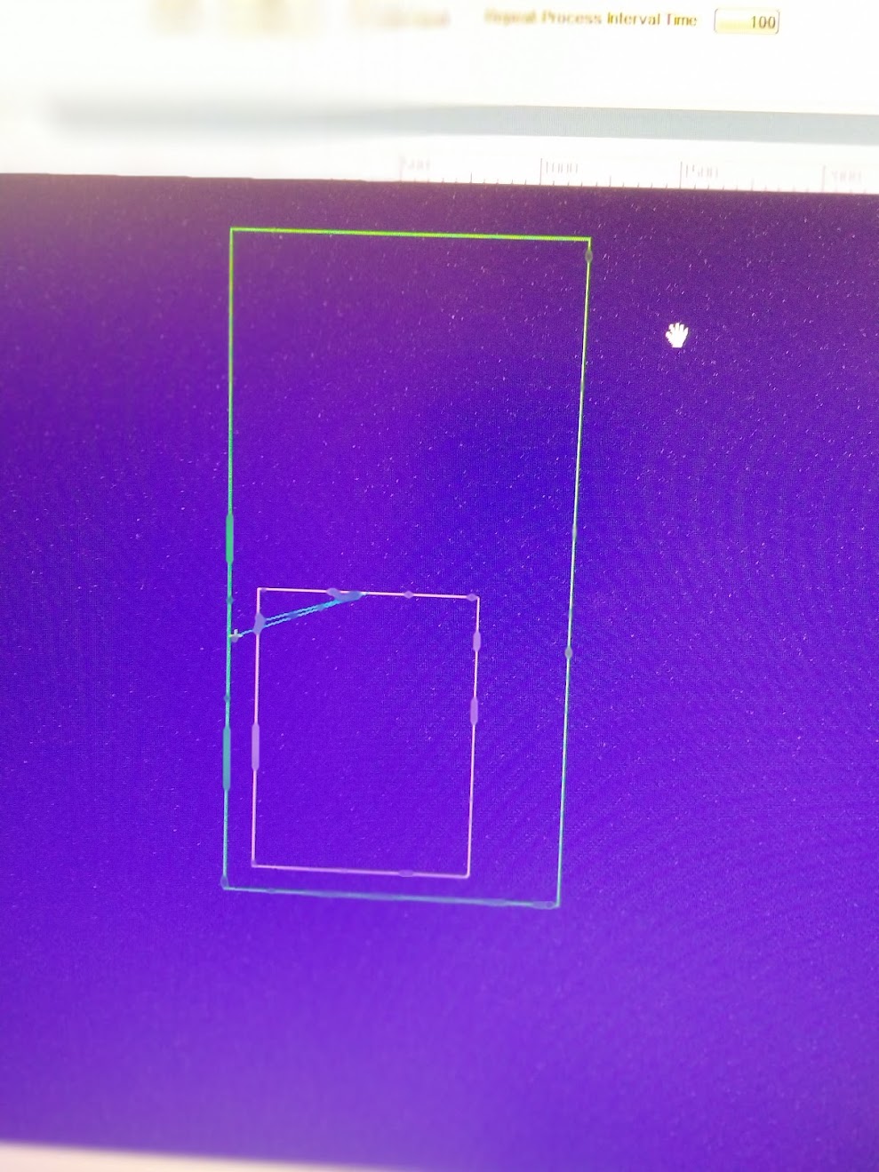
The result can be simulated beforehand to give an idea of the placement of the different toolpaths.
The result
I could not do the engraving of the world map on top due to time concerns.
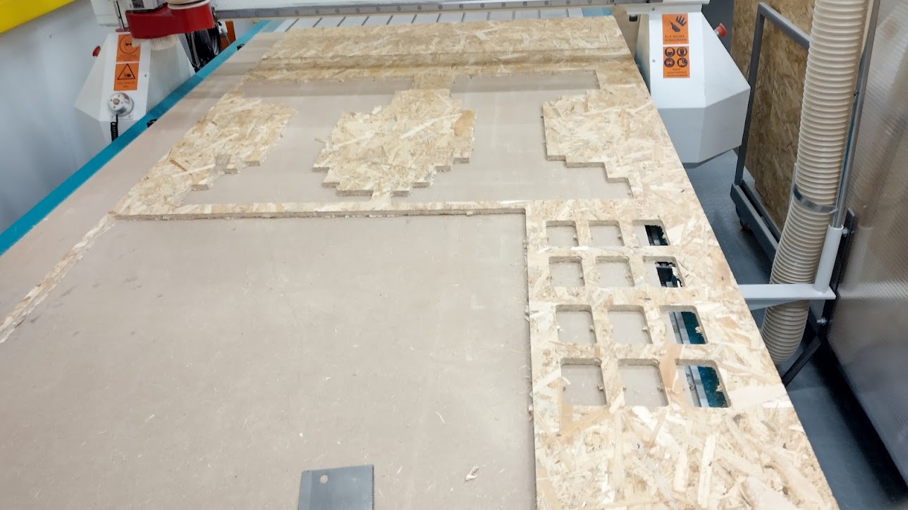
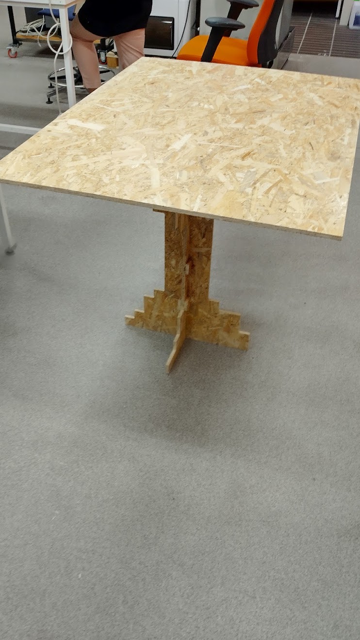
After about an hour of waiting, this was the result:
And once assembled:
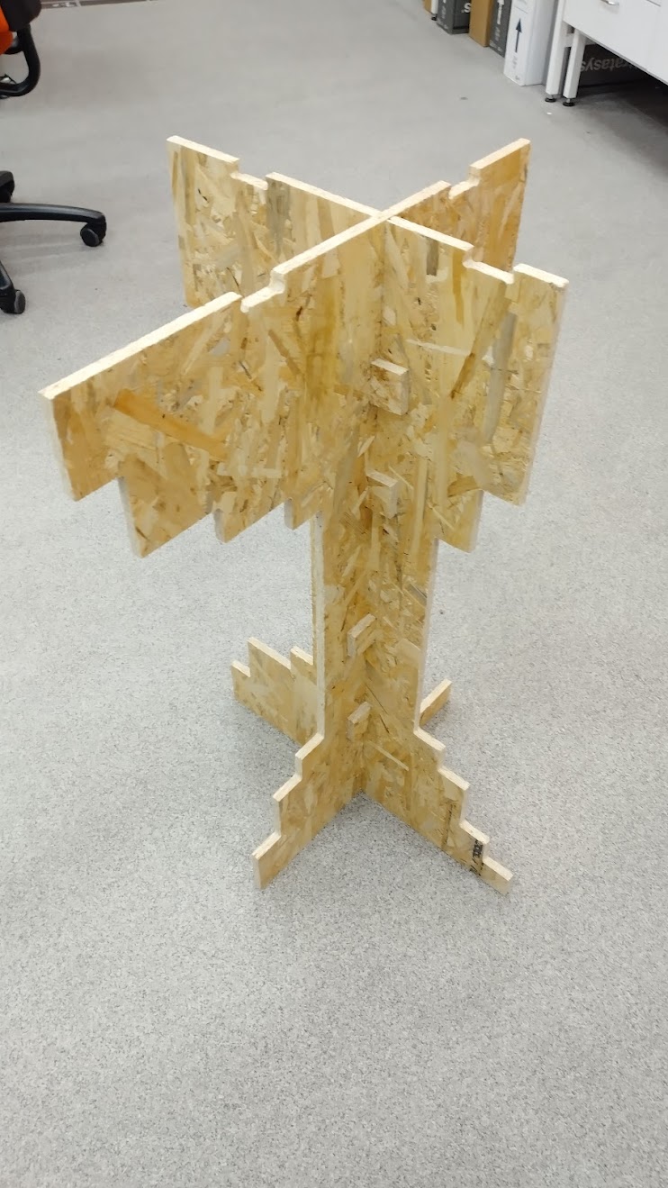
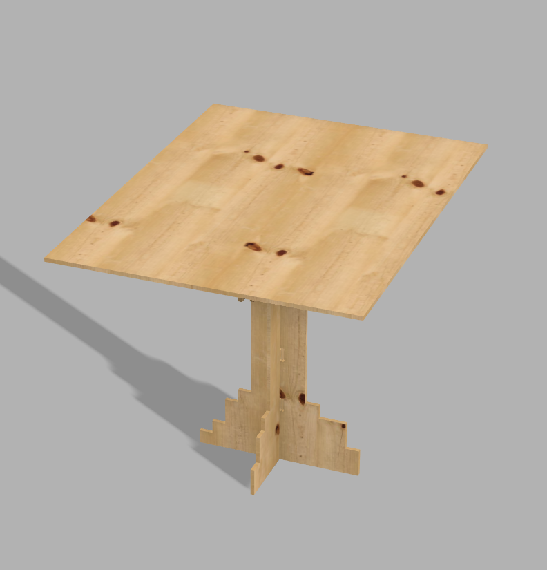
I consider this a success when comparing it to the original design.
Files
This is how the table should have looked like
NC Programs
The tabs used for assembling (Mill this two times)