4. Computer controlled cutting
This week I learned to use the laser and vinyl cutters.
Vinyl cutter
Physical Set Up
The first step is to set up the vinyl cutter, following the next steps:
-
Turn it on
- Yes, at first I forgot to do that…
-
Place the vinyl roll in the back of the cutter, unlock the cutter, and place the end of the roll underneath it.
- You can also use a smaller piece of material if you want.
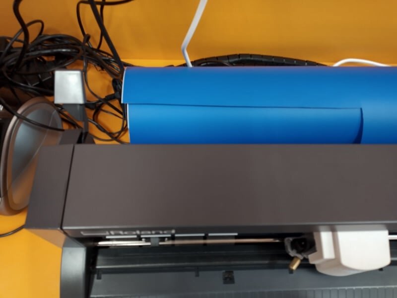
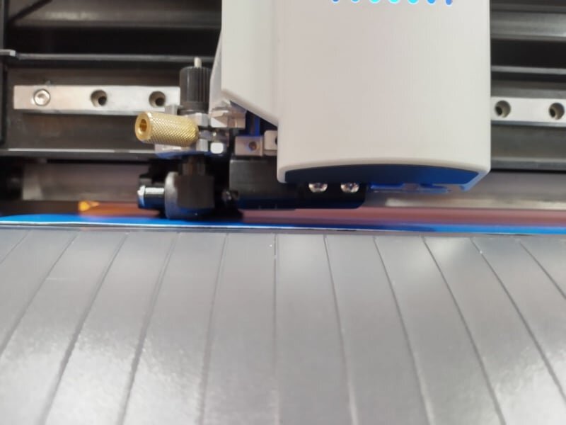
- Set the separators according to the size of the image you want to cut. Be careful to place them only under the white markings.
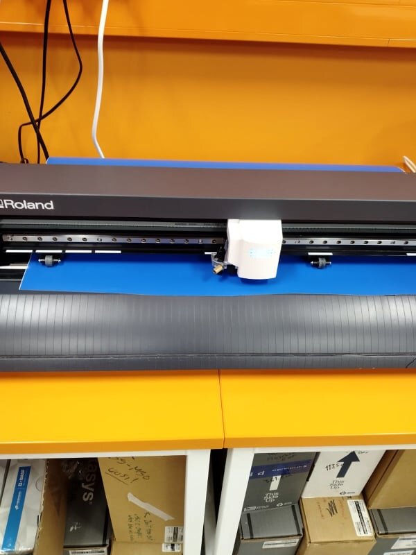
- Set the origin using the stick, just as in the laser cutter, but with a single axis. This will be the left side of the image.
Preparing your file
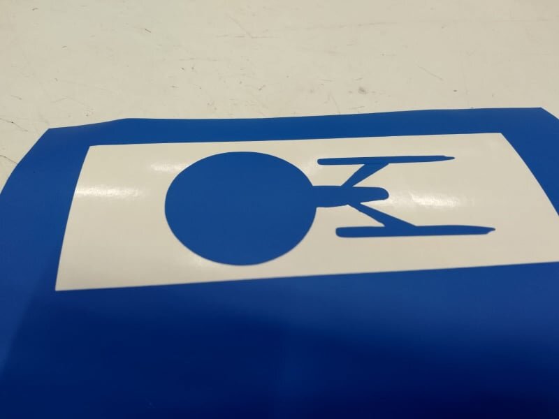
As the name says, the machine is just a cutter, and it will not engrave any fine details. Vector images are quite useful for this purpose, as the cutter only cares about the edges. In my case I vectorized the USS Enterprise, but I first had to eliminate all the lines in the middle of the picture, otherwise it will cut them and ruin the vinyl. Which happenned once.
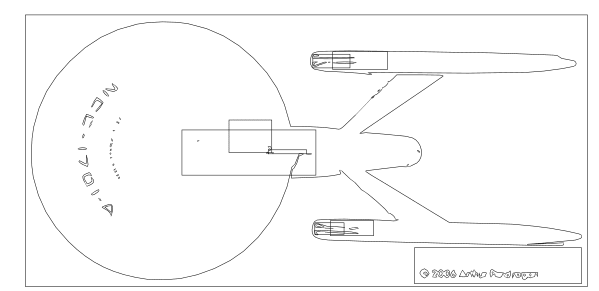
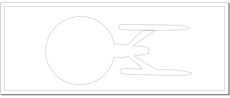
Be careful to delete all the unwanted lines…
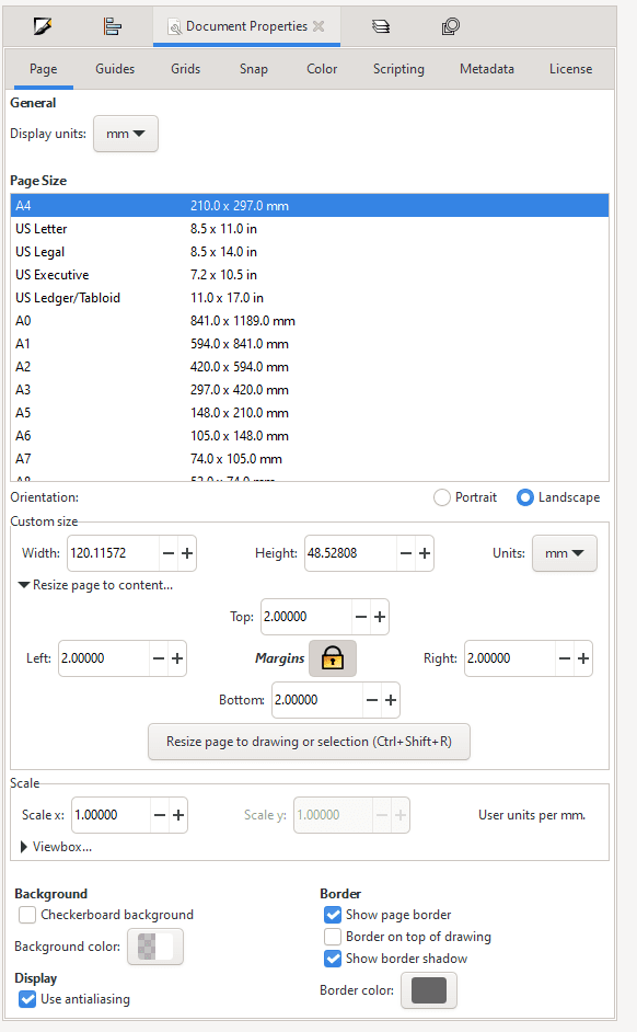
The origin must be set to the left bottom corner or you can resize the document according to the the size of the drawing. A small margin should be left AND the size of the vinyl workspace should be set according to the width of the design shown in the software, otherwise three things could happen:
-
The cutter doesn’t cut anything.
-
It only cuts the exact shape, making it difficult to remove it.
-
It shoots out half of the vinyl roll without actually using it.
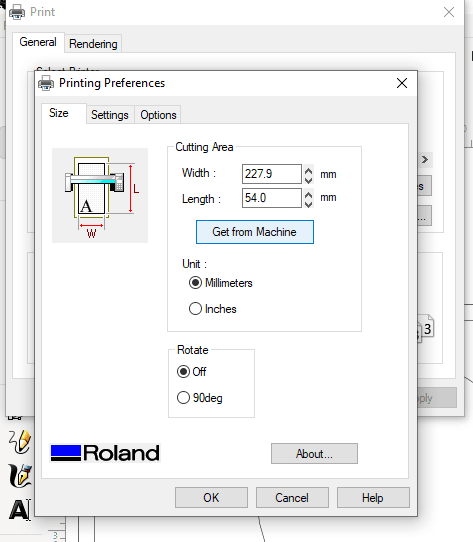
The Get from Machine button will show the measured width of the vinyl roll by the vinyil cutter.
Result
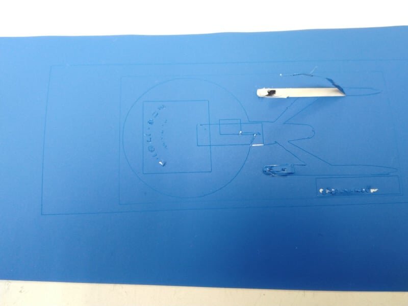
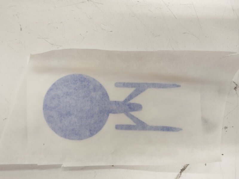
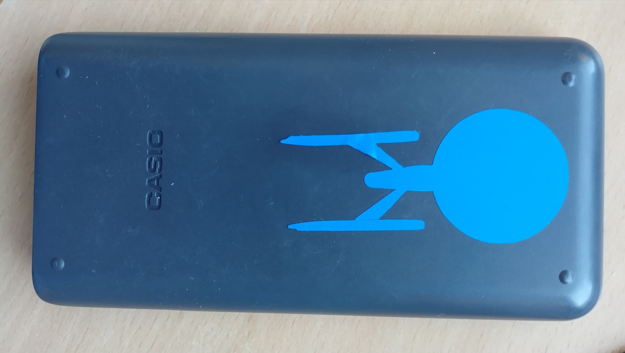
All unwanted vinyl pieces can be removed using some small tweezers, trying to use the fingers could potentially ruin the product, specially when dealing with intricate designs. The final result should be something like this:
Sticky paper can be placed on top to remove it more easily.
Laser cutter
A detailed description about the set up process can be found in the group page. This is where we learnt concepts such as kerf, speed, DPI and frequency. I designed a parametric construction kit for building a box which can be found below. This week I will skip the first steps in creating a sketch in Fusion 360, as they were already explained in the third week. The new element about this, is that I can now use parameters. These can be easily added/modified under Modify > Change parameters.

I used three parameters for this sketch:
-
m_w: The thickness of the material, in this case 3mm; which will be the thickness of the both bodies in the design AND the uncorrected width of the slots used for assembling (see below).
-
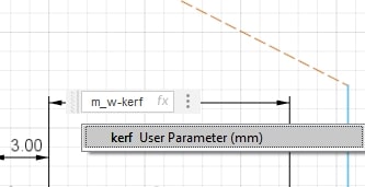
kerf: The material removed by the laser cutter, as seen below, the width of the slots is m_w - kerf. This will make the slot 0.5kerf shorter on each side, which will give the slot the actual dimension I desired. (Why 0.5 kerf? - Because the other 0.5 kerf goes onto the raw mdf plate)
-
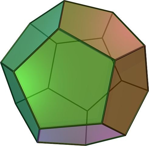
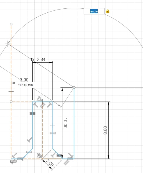
angle: The angle between any two faces in the dodecahedron, used for determining the inclination of the joints.
Parameters are essentially, just the dimensions of the parts in a sketch, this can be useful when a design will be used multiple times, each time accounting for the change in a variable. This time I decided to make a regular dodecahedron.
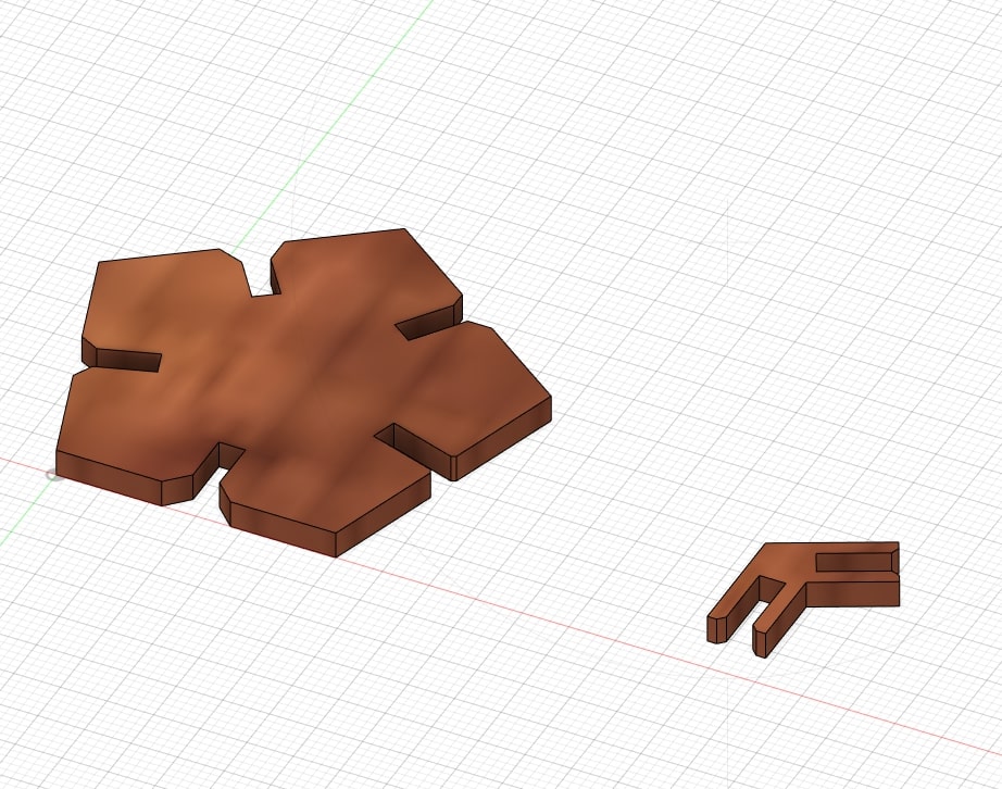
The faces
I would first have to design the faces and then some way to join them. When I started designing the pentgonal face, it was somewhat far from what it was supposed to look like…
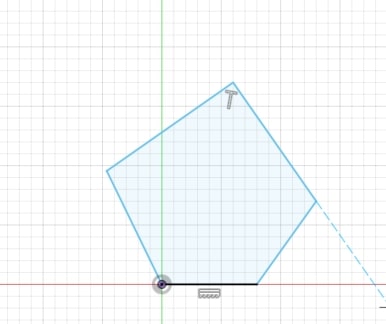
I tried using constraints.
But I certainly didn’t do it correctly.
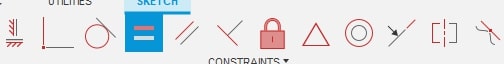
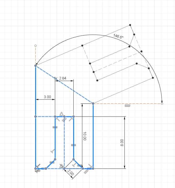
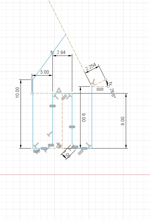
I gave up and decided to build the face using dimensions, I had to specify the length and angle of each line. This can be done by simply specifying the length and angle(inclination) of each line, or after placing the line by “Sketch > Sketch Dimesion”
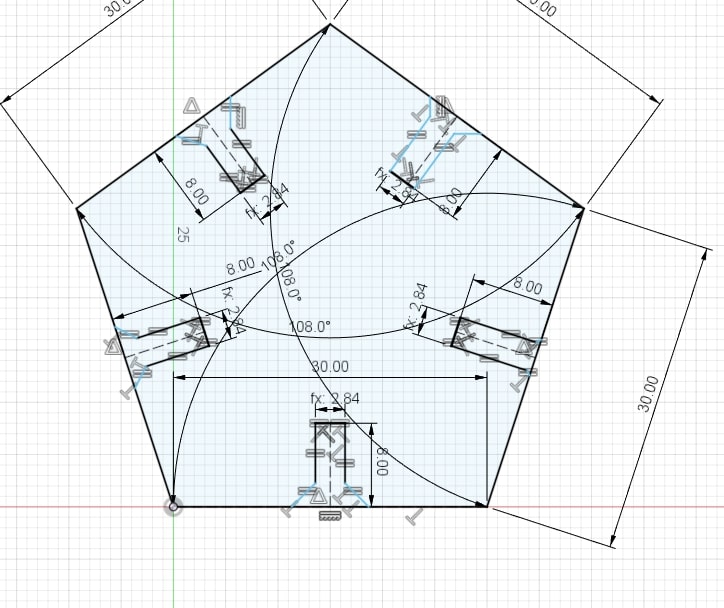
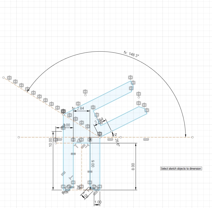
And then I added the slots to be able to connect the faces together.
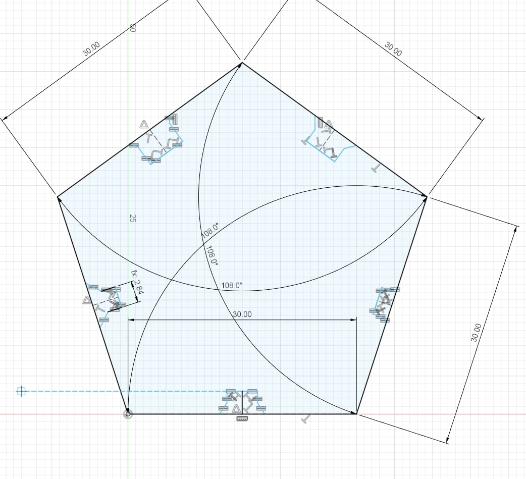
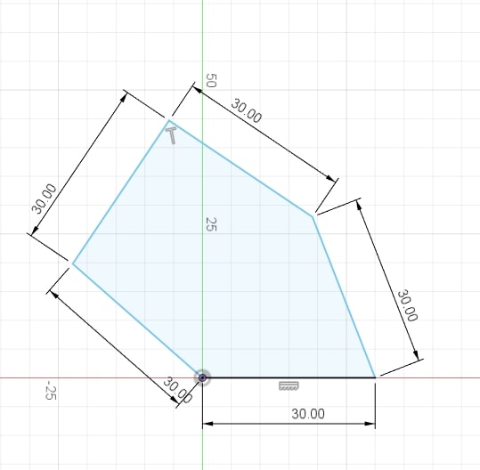
They looked quite irregular at first but I quickly fixed that using constraints and parameters.
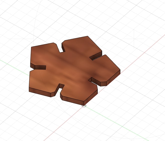
Then I extruded the shape (Create > Extrude) and gave it a texture (Right Click > Appearance > Wood)
The joints
This little pieces would lock the faces of the dodecahedron in place by fitting in the edges, just as before I made a veeery rough sketch and slowly gave it some shape using constraints.
Then I reflected this side (Create > Mirror):
And extruded it.
Seting up the cutter
In the DRAWING section of Fusion, I created a pdf of the footprint by exporting it. (Upper Right Corner)
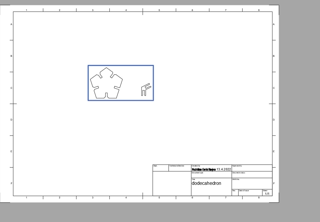
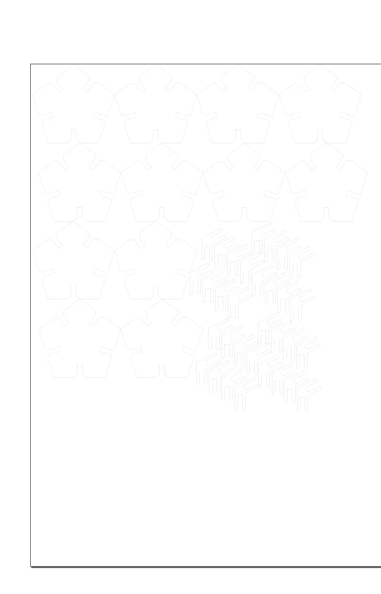
And using InkScape I copy-pasted the same shapes multiple times. (12 faces and 30 joints)
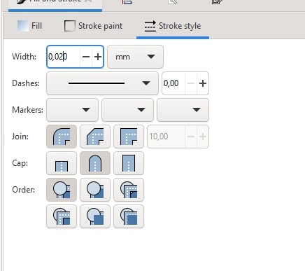
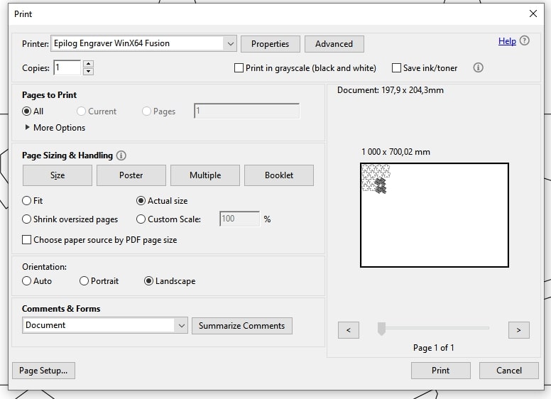
I had to make sure the lines were no more than 0.02mm thick so that the laser cutter works properly.
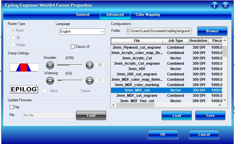
Just like any regular printer, I pressed the button print and then changed the settings to 3mm MDF Cut
The laseeer
I placed the MDF plate.
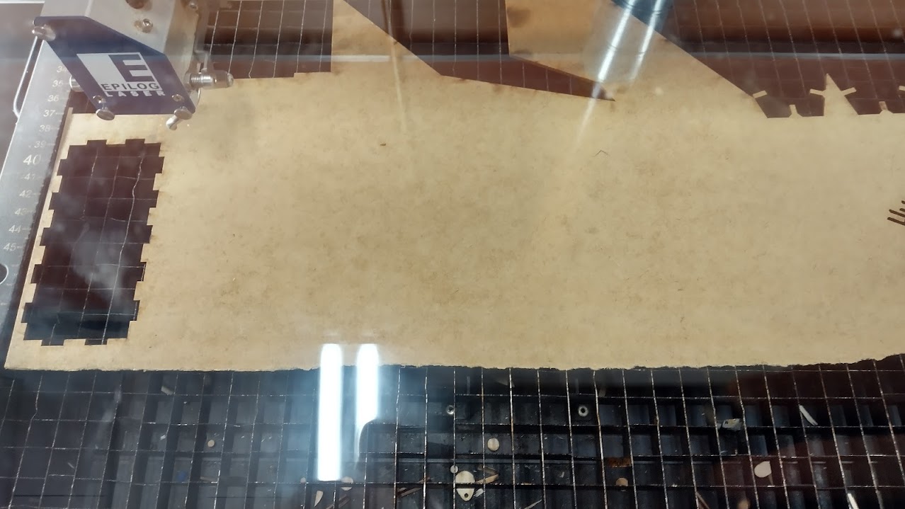
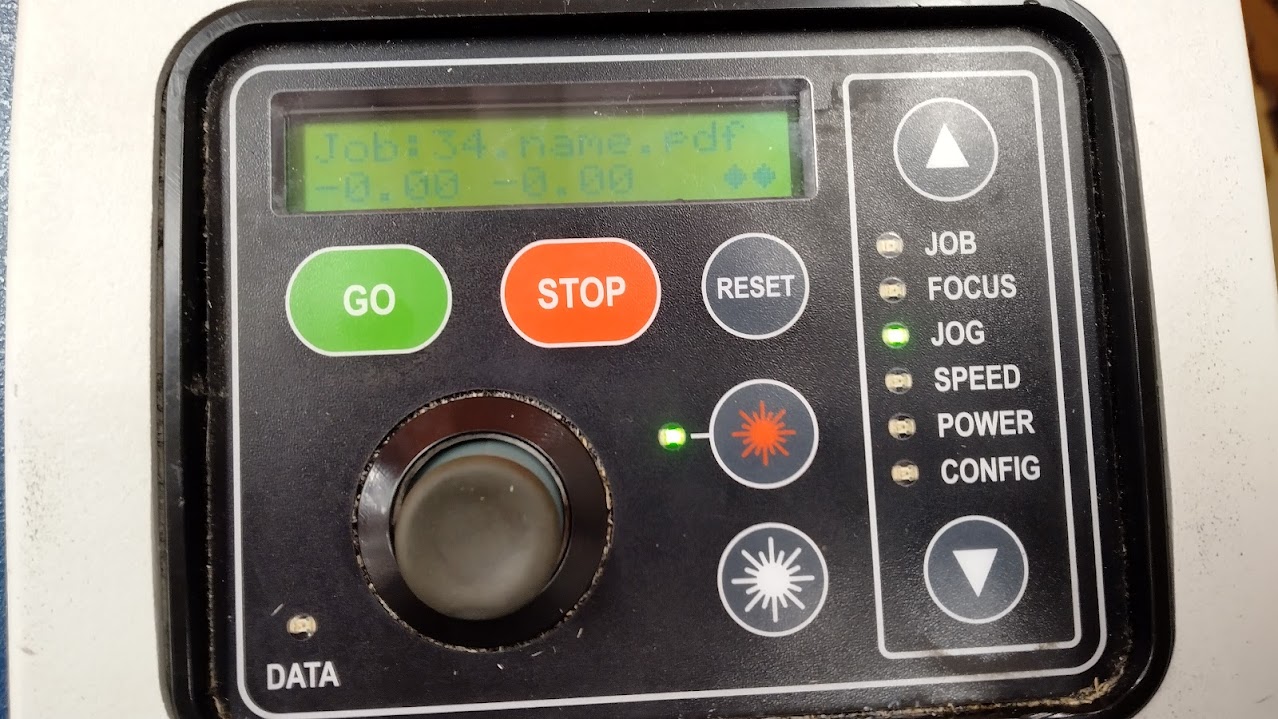
I set the XY origin and the Focus distance.
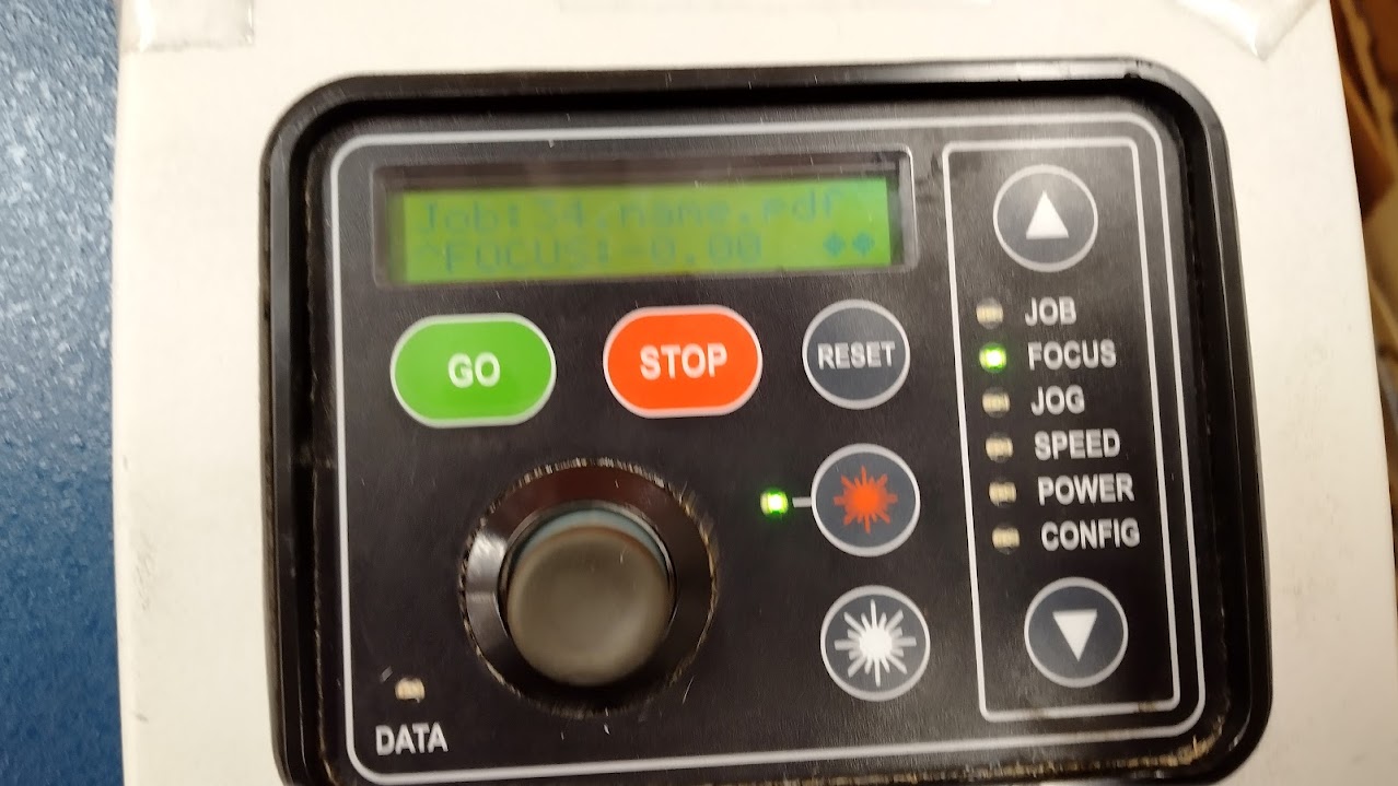
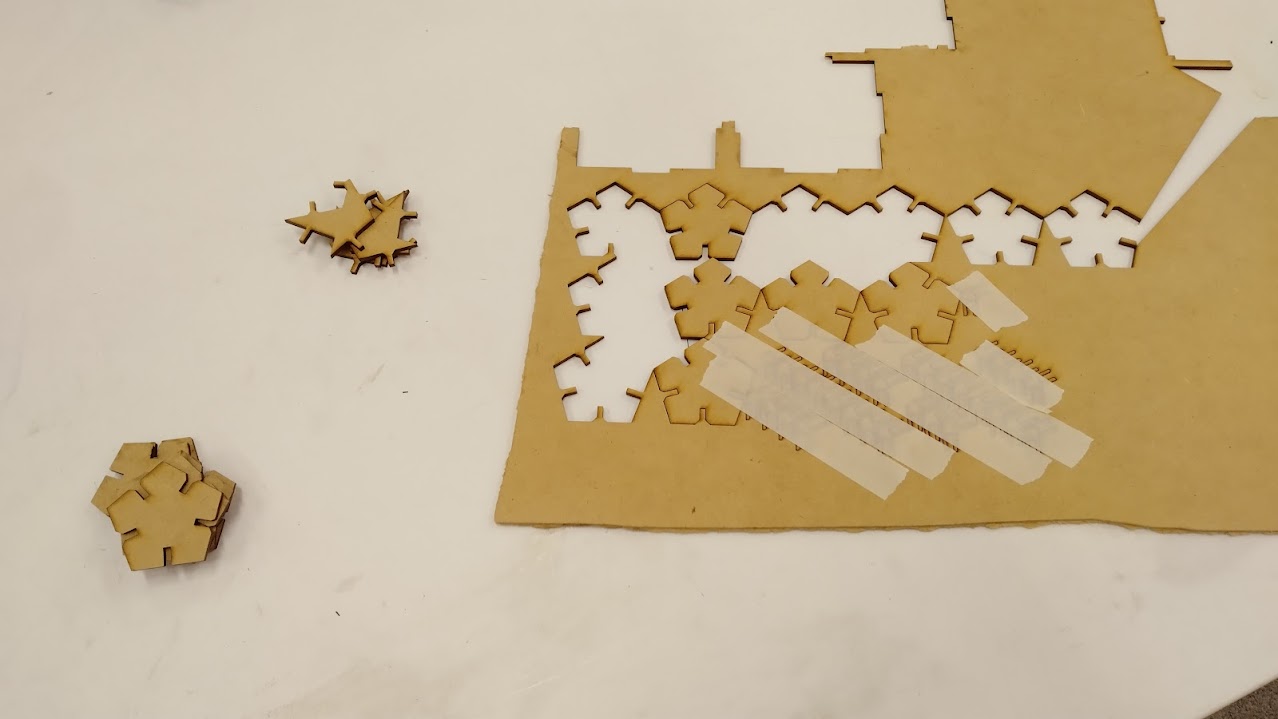
There was no engraving at all here, so it was quite quick. I had to use some painters tape to be bable to take out the joints from the rest of the board without them falling to the bottom of the machine.
For more detailed instructions visit the group assignment
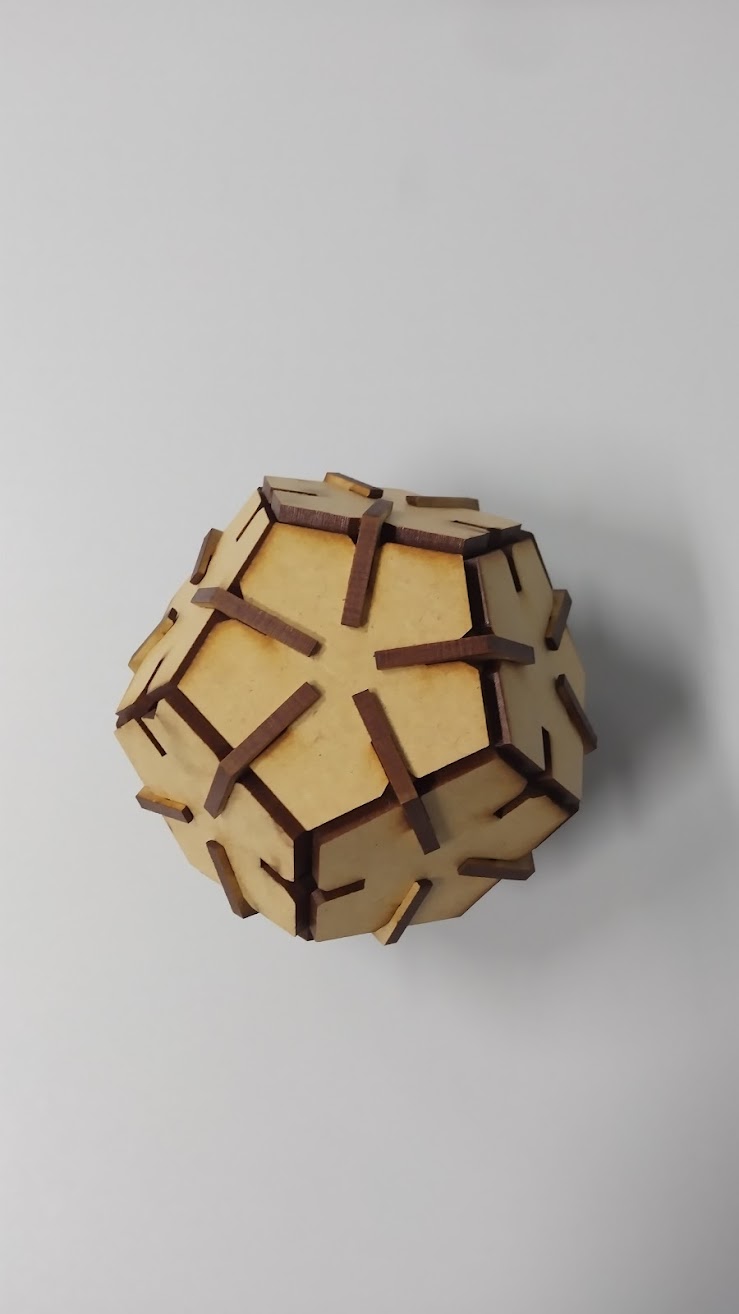
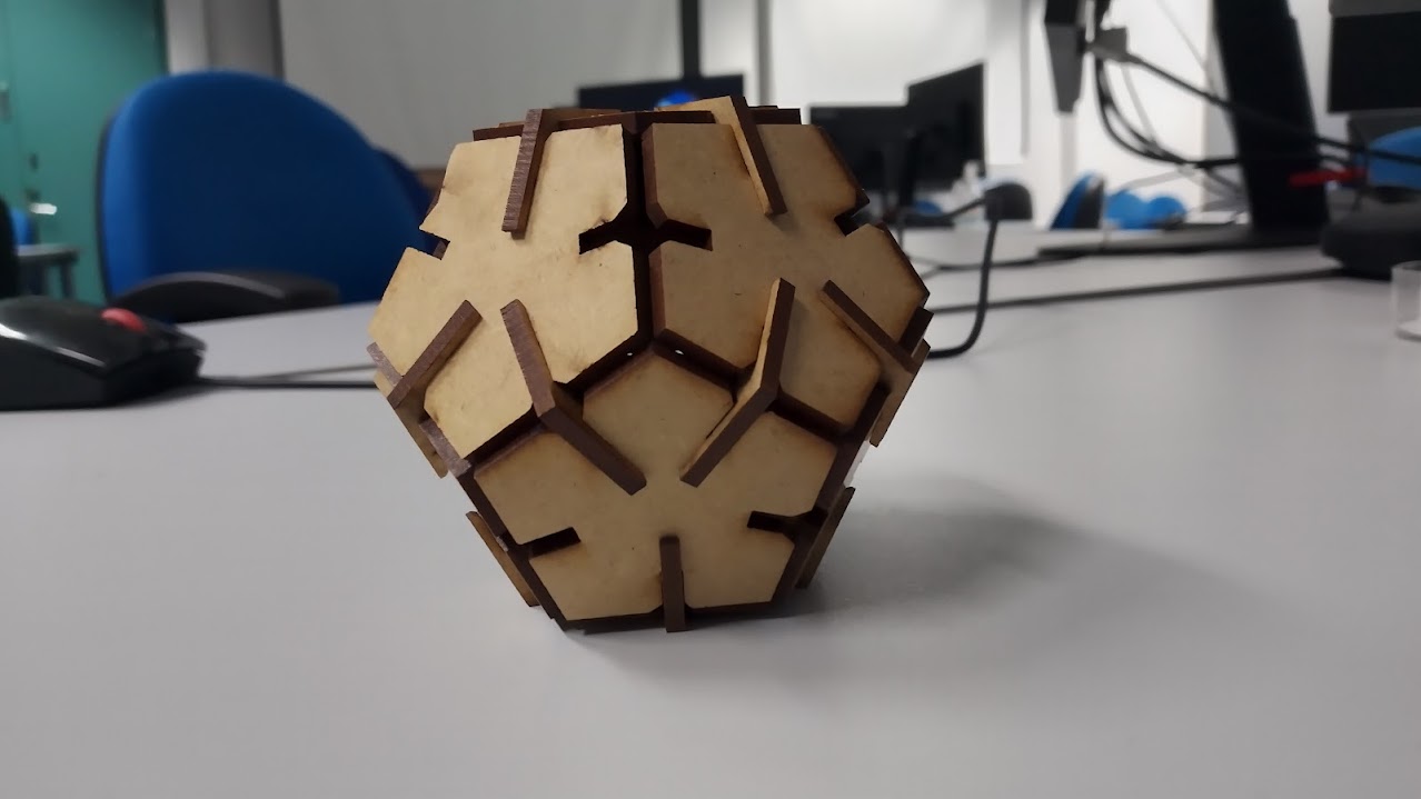
Result
This was a pretty nice shape, altough it was quite a problem to assemble it.
Useful Links
Group assignment about laser cutting