4. Computer controlled cutting
Our Homework this week
Our assignment this week is to:
Group assignment:
- Characterize your lasercutter’s focus, power, speed, rate, kerf, and joint clearance

- Document your work to the group work page and reflect on your individual page what you learned
Individual assignments
- Design, lasercut, and document a parametric press-fit construction kit, which can be assembled in multiple ways. Account for the lasercutter kerf.
- Cut something on the vinylcutter
Learning outcomes
- Demonstrate and describe parametric 2D modelling processes
- Identify and explain processes involved in using the laser cutter.
- Develop, evaluate and construct the parametric construction kit
- Identify and explain processes involved in using the vinyl cutter.
Have you answered these questions?
- Linked to the group assignment page
- Explained how you parametrically designed your files
- Documented how you made your press-fit kit
- Documented how you made your vinyl cutting
- Included your original design files
- Included your hero shots
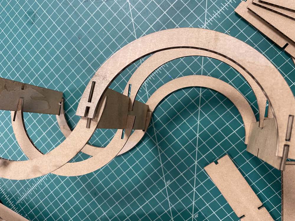
My Press Fit Construction Kit
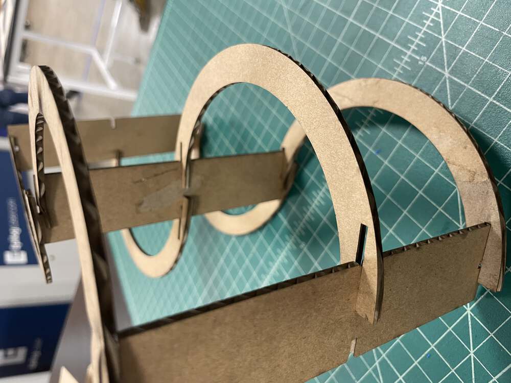
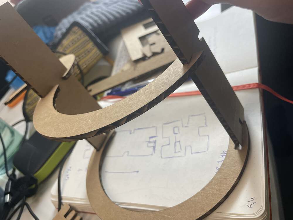
I built a pretty simple kit that ultimately still needs some tweaking…but it is a prototype for what I want to work on for make something big week. Here is my ‘hero’ shot:
And here are my files for the week.
Below, I’ll go into more detail about the journey to this kit…but first, the group project!
Group Project
Our group assignment is to characterize your lasercutter’s focus, power, speed, rate, kerf, and joint clearance and to document your work to the group work page and reflect on your individual page what you learned. I am copying some documentation of the group assignment below because we are getting a 404 error on the group page. However, it is also uploaded to our LCCC group repo!
From my fellow LCCC co-hort member Jim Hart’s site, I found the LCCC Group page from a few years ago. I used this page to better understand the scope of the group assignment and recreated the files they used for testing Kerf and joint clearance. One note I’ll mention is that Jim and I are working together remotely…so we are using different machines and are on different schedules. But we have been doing our best and I am learning a lot from reading Jim’s repo. So, our group work is asynchronous and remote. Sometimes I use ‘I’ in the group documentation but please know that it is a group effort.
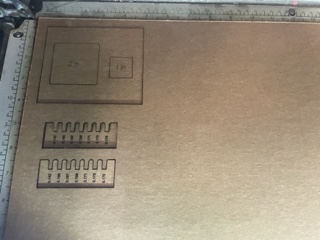
When laser cutting, some amount of material is lost due to the physical properties of the laser–and to some extent, the properties of the materials being cut. The amount of material lost in the cut is the kerf. To measure kerf, I created a one inch square and a two inch square in Inkscape, brought it into CorelDraw, cut it on the laser cutter, and then measured around the outside of each square and also the negative space remaining from each cut. You can see these images below:
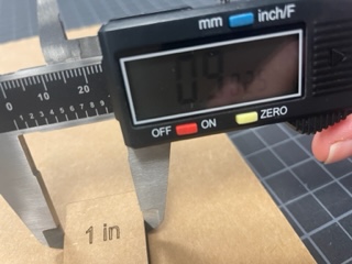
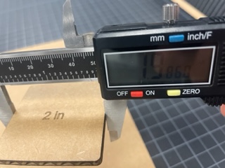
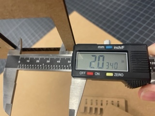
I only measured on one side for each square so my values may be a bit less precise but should give a close idea of the kerf. For the two inch square, the kerf is 2.034 - 1.986 = 0.048 inches. For the one inch square, the kerf is 1.033 - 0.9025 = 0.1305. The average kerf would therefore be 0.08925. This seems large to me, compared to the average the previous group found of 0.015 inches. My guess is that either the calipers were having issues – the battery seemed very low – or else perhaps my equipment settings were significantly different from the previous group.
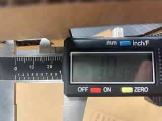
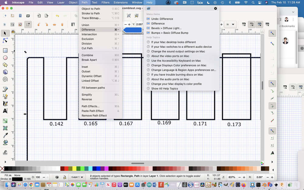
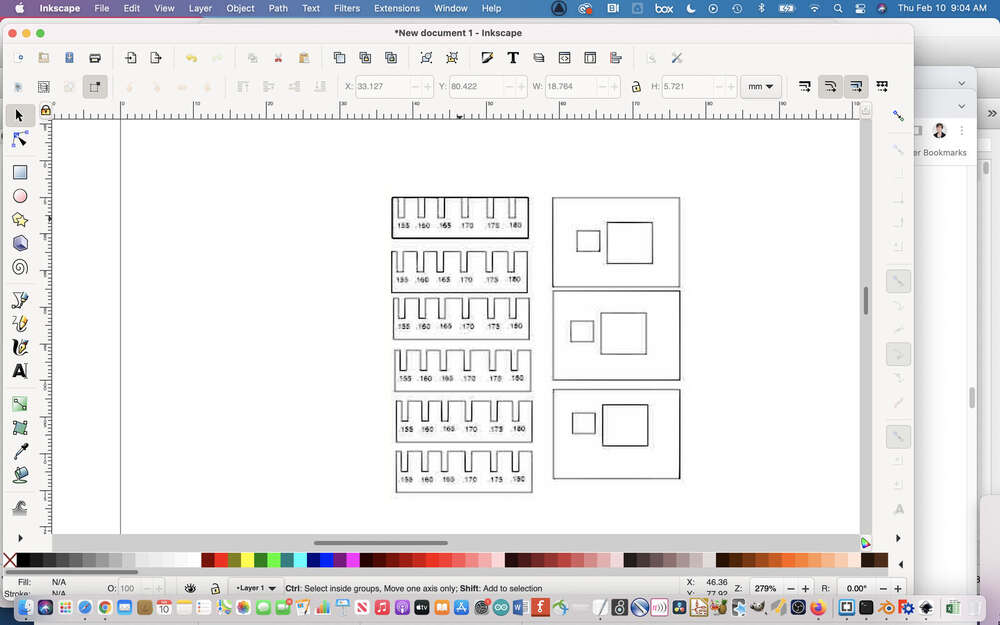
Subsequently, I worked on the joint clearance assignment. I measured the thickness of the cardboard on hand and then created a comb with the spaces between the teeth dicated by the measurement I had taken. I used both the initial measurement and then also some smaller measurements to create these spaces to see what might make the most snug fit.
Below is an image the file I created – I initially made it in Inkscape but after I moved it to the lab machines and imported it into Corel Draw it still needed a bunch of work. This process was a bit slow because I was not yet working parametrically, originally. Later, I made a parametric version in Fusion. I go into much more detail about parametric design below, so hopefully that will suffice for illustrating how I worked parametrically. I made the second comb in a bit of a rush at Think[box] and did not have time to properly document it.
Here was the first version of making the software comb as it was being built: I used the difference tool to cut excess lines:
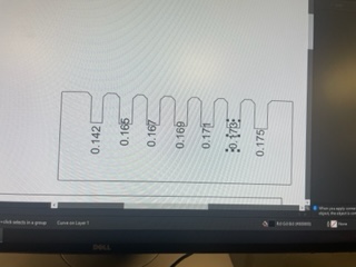
This is me adjusting it further in Corel Draw.
To do the comb joint test, you need to decide on a range of values to use for the joints. We measured our carboard to determine the widths to test:

Here is the finished version in CorelDraw:
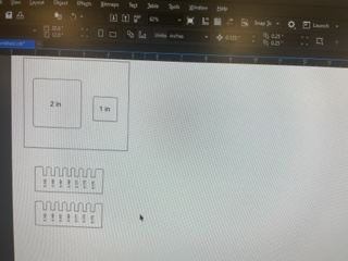
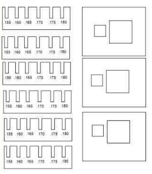
And here you can see the whole file:
LCCC uses CorelDraw to send materials to the Epilogue software, so you have to optimize your files for CorelDraw:
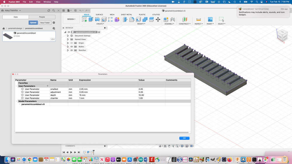
Here is the parametric version in Fusion:
The original LCCC group documentation:
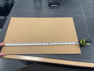
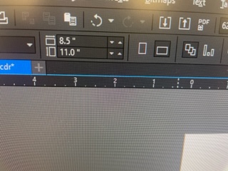
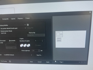
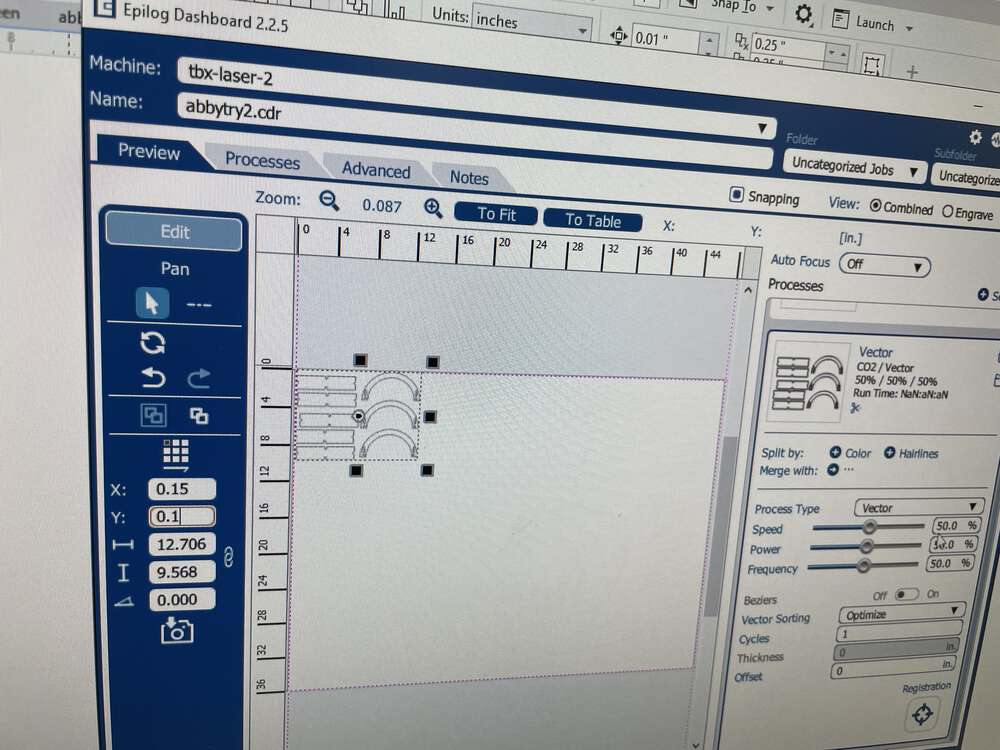
In Corel Draw, which is the program we use to talk to the laser cutter, it is important to tell the laser cutter the correct size of the material you are going to use:
First measure the size. Then enter the values into the software.
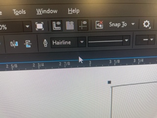
It is important to make sure that everything you want to cut is set to hairline:
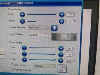
In the Epilog software dialogue, you can define all sorts of settings including what you want your laser to do, The first time around, we set it to combined raster and vector, since we wanted to cut the comb and also see the size of the cuts rastered on the cardboard. This took forever and wasn’t super effective, so we subsequently used vector scoring instead.
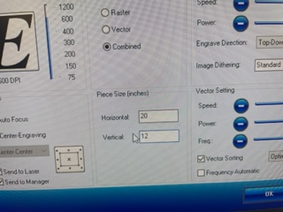
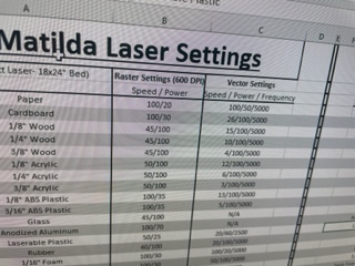
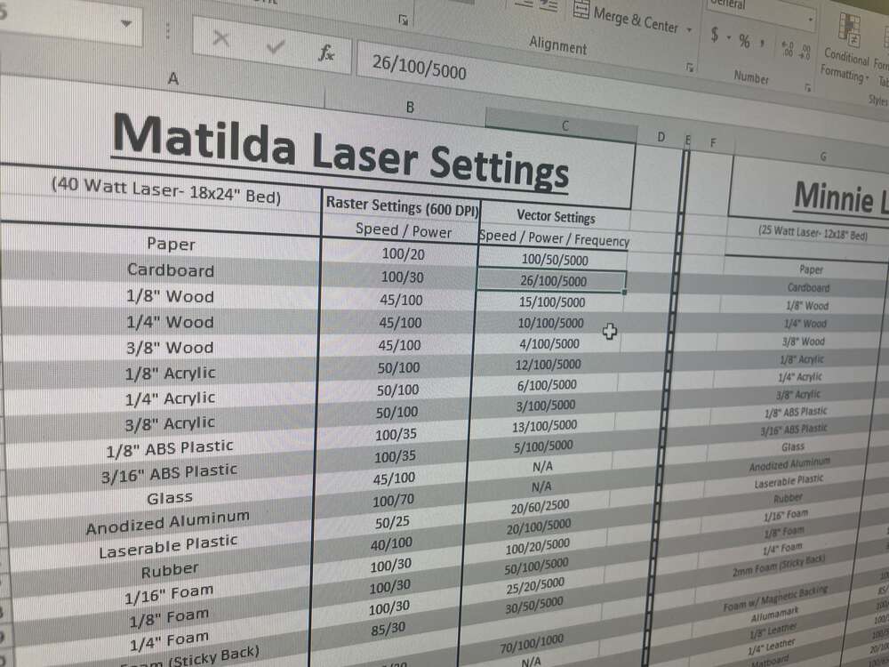
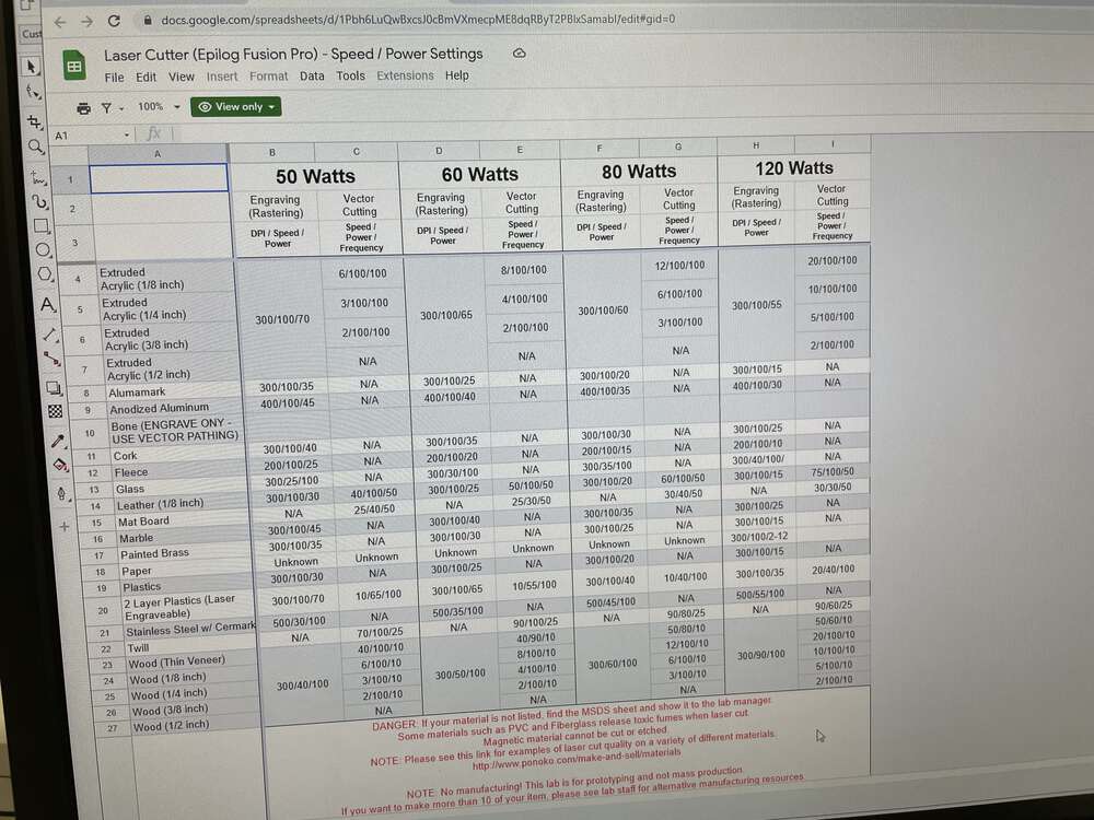
You also need to assign settings for speed, power, and frequency based on the materials you are using. Thankfully, LCCC has a handy cheat sheet so we knew what settings to use for cardboard.
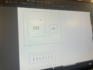
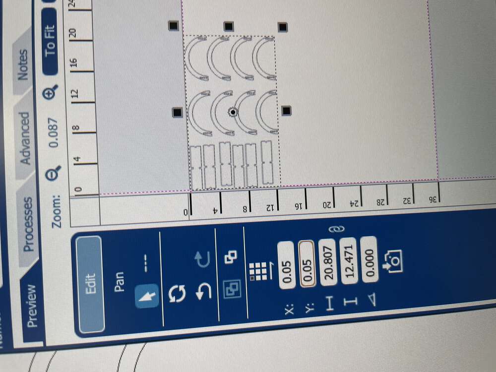
Here we are checking to see if the comb and kerf tests are set to be in the proper defined area:
Here is the final digital file:
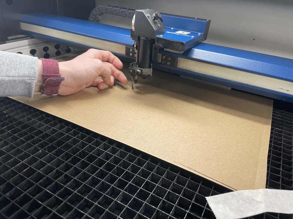
Now it is time to use the laser cutter!
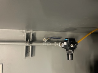
It is important before running the laser cutter to make sure that the airflow is on:
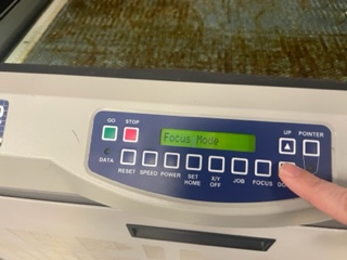
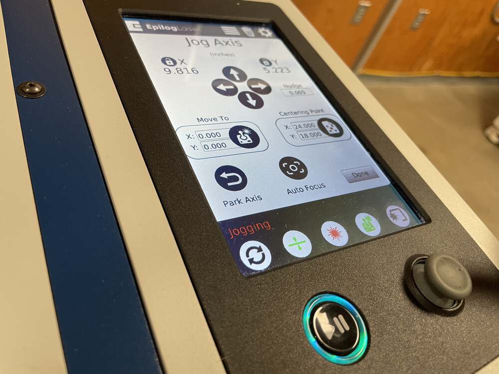
Using the laser cutters user interface in focus mode to raise and lower the bed to adjust the laser focus.
First you need to flip the little magnetic autofocus tool down.

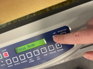
Then you need to adjust the height of the bed until it just touches:
Continuing to adjust the focus but now I raised the bed:
To exit focus mode you hit the reset button:
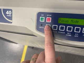
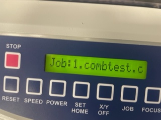
And then when you see your file name, you can tell it to go!
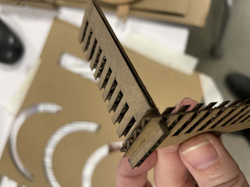
We cut the materials!
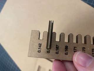
Here is a close up of the laser cut comb with vector-scored measurements:
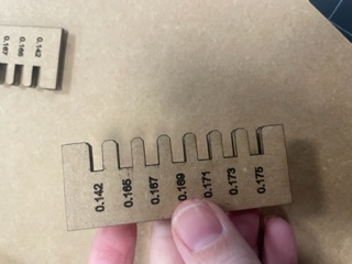
It fits! 0.165 was the magic number.
During global open time, Adrian showed his example file where they tested the speed and focus for the laser cutter. It looks amazing and you can find it here. I didn’t get to test this because I didn’t have enough time at the lab. I hope to be able to test it subsequently.
Parametric Design in FreeCAD
Last week, I followed Neil’s brief Fab Academy video on parametric design to get a taste for the process in FreeCAD. But I was still confused about how to apply this to the types of geometries I knew I needed to make in order to make the press fit construction kit I need to make for this week.
I downloaded the example joints file we saw in class and selected the different joints to look at their properties. I saw that the section with constraints had different values that were being controlled parametrically.
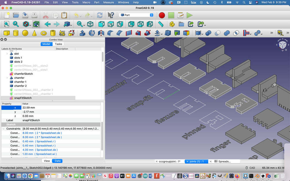
I was still confused because no matter how many times I tried to add different constraints using the tools in the Sketcher workbench, no constraints were popping up in the modeling dialogue that I could work with. I did some searching and found this video which finally helped me understand how to work parametrically in FreeCAD a bit more reliably.
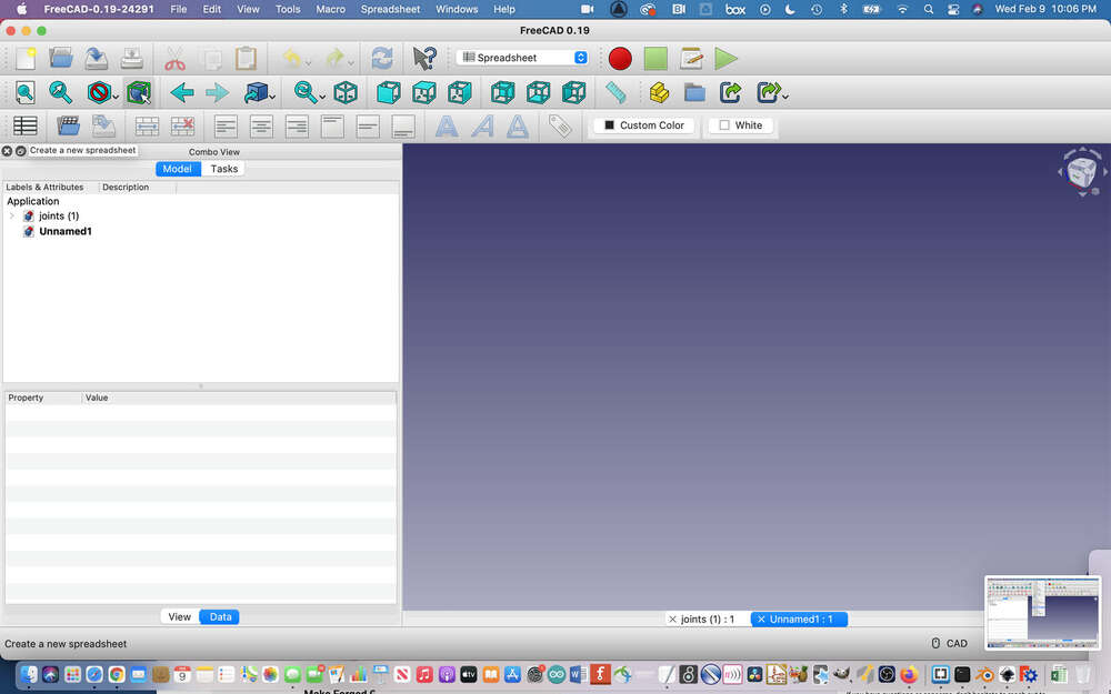
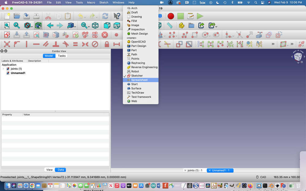
I toggled over to the spreadsheet workbench:
I made a spreadsheet in the spreadsheet workbench:
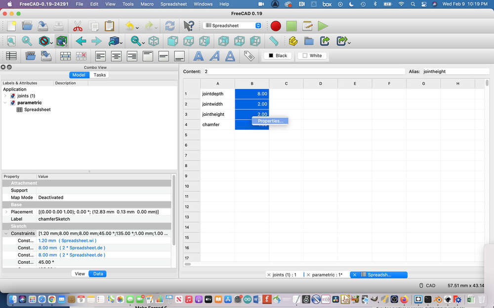
I assigned the unit value to mm:
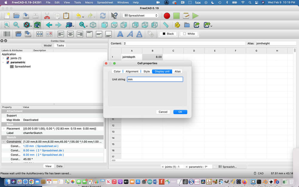
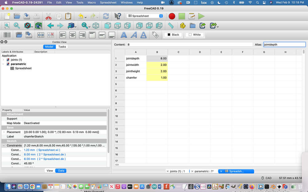
I added aliases to my values:
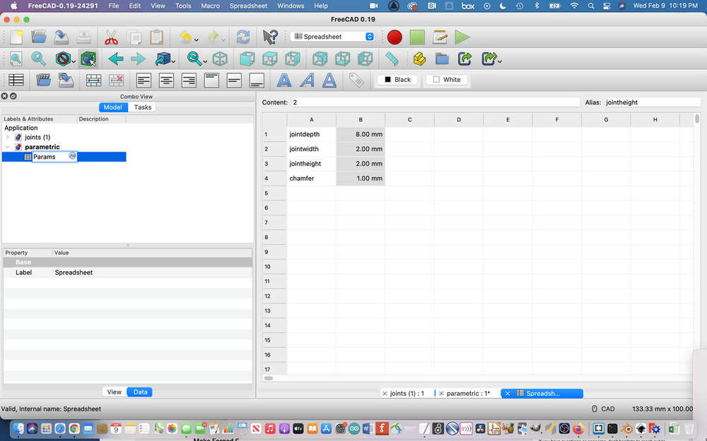
And renamed the spreadsheet:
I added a distance constraint:
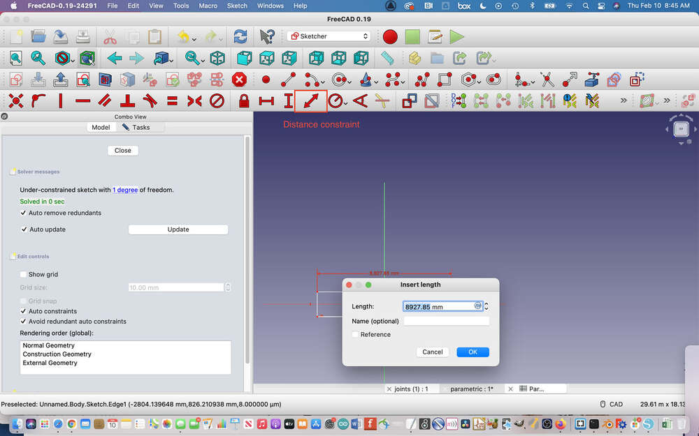
And tried assign a parametric value to the distance constraint from the spreadsheet:
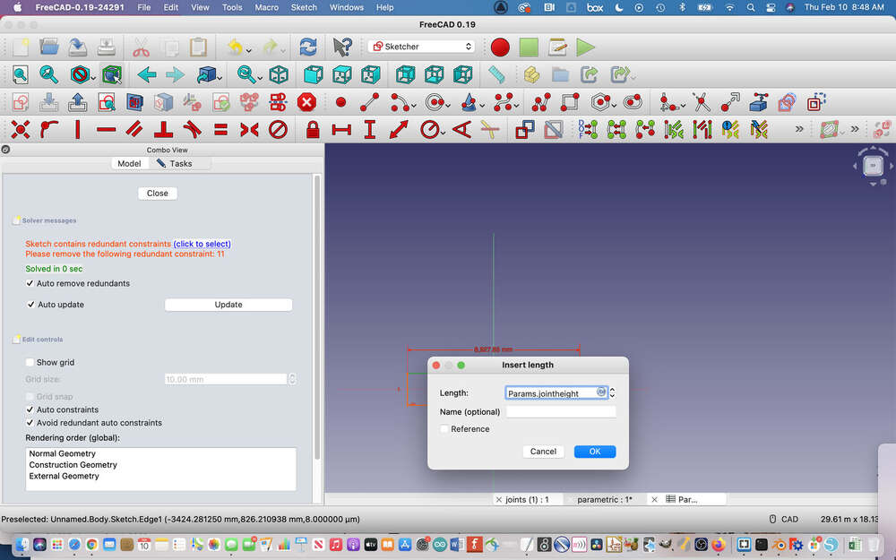
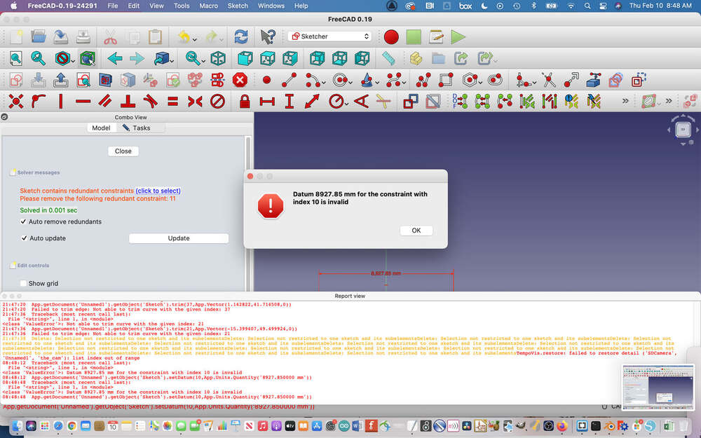
It didn’t work:
I also sometimes ran into redundant constraints:
As you can see, I was still struggling a bit and when I visited LCCC on Thursday to work on the group project, I spoke to my instructors about CAD software options for parametric design on a Mac. They recommended that I switch over to Fusion 360. I decided to go ahead and do so despite needing to start from scratch with a new piece of software and I am glad that I did. I think FreeCAD is a bit difficult to start out with as a beginner. I still really like Blender and I want to make sure to try to keep up with it, but for parametric design Fusion 360 is much more intuitive to use than FreeCAD or Blender.
Designing My Press Fit Construction Kit in Fusion
So, although CAD week was last week, I spent some time this week learning Fusion from scratch. I began by following the Lynda.com introductory Fusion tutorial.
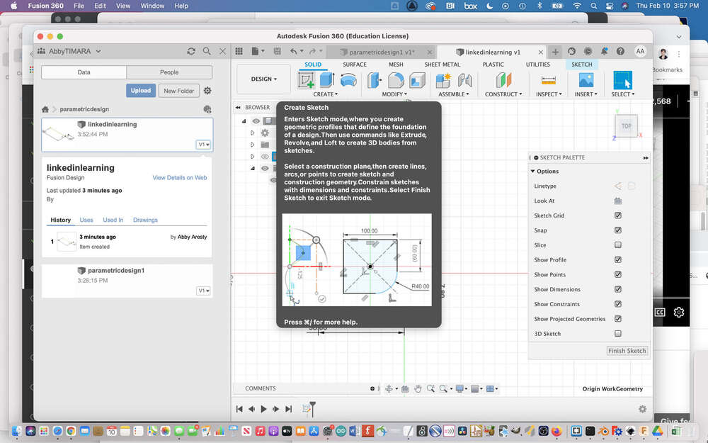
I learned about the workspace.
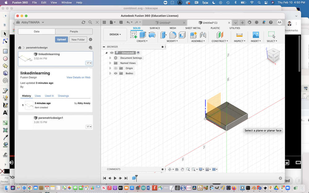
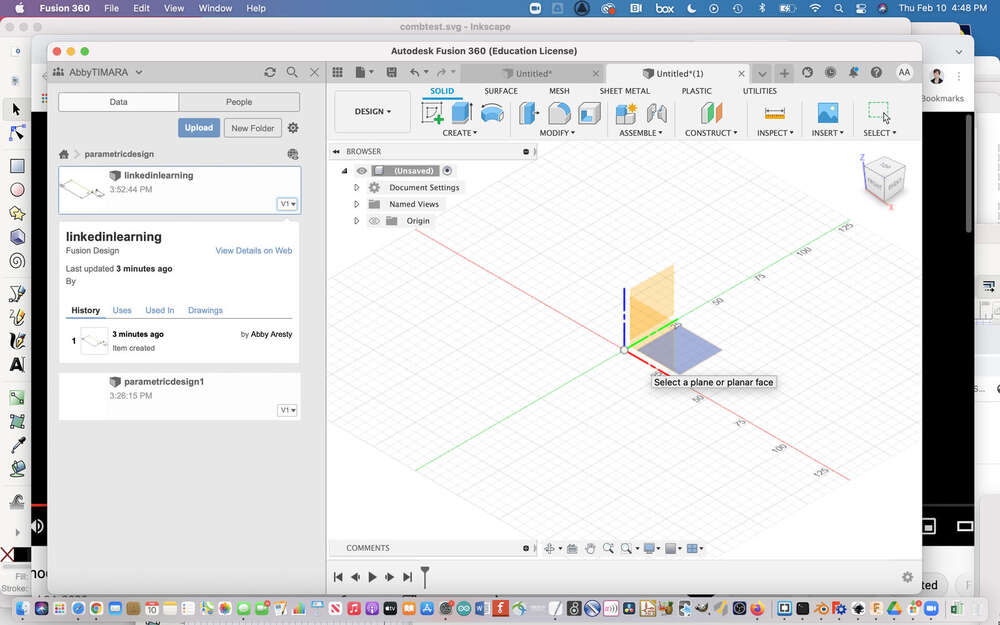
I got familiar with selecting different planes:
And I learned how to use one object to make a cut in another.
I found the extrusion tool.
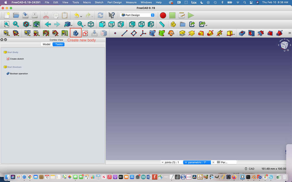
I learned the difference between creating a new body vs. using extrusion to cut an existing object:
And made my first parametric joint! I’ll include more documenttion on the parametric design process in Fusion below.
For my press fit construction kit, I was inspired by this instructables tutorial. I also want to make something that I might be able to use as the basis for my ‘make something big week,’ assignment and this design felt like a good starting point for what I want to make.
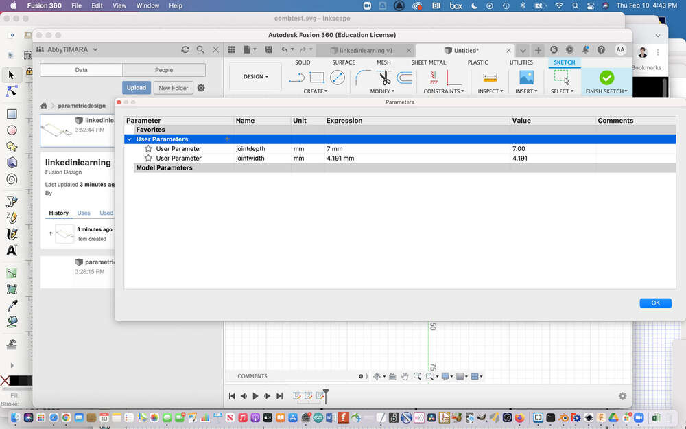
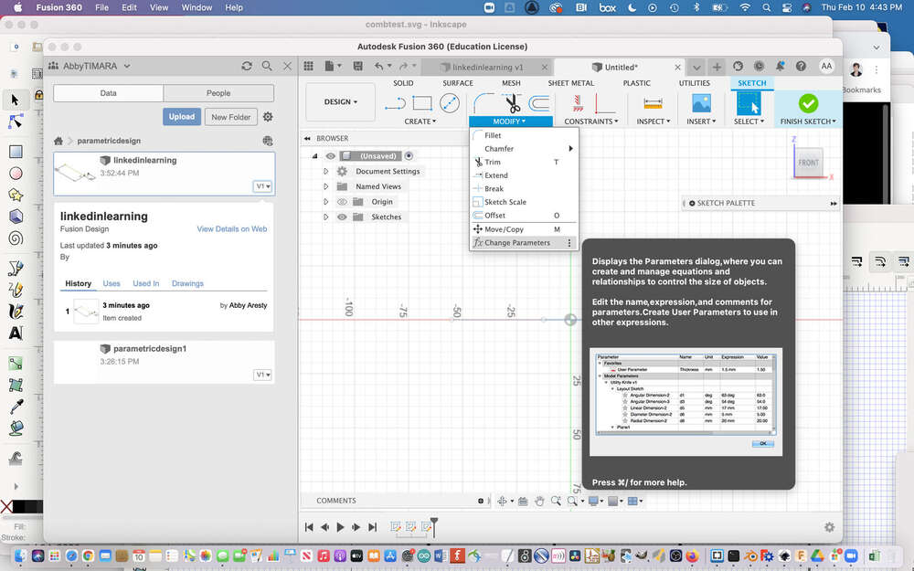
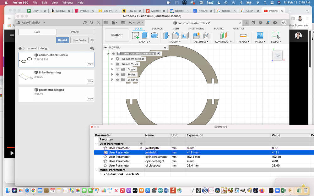
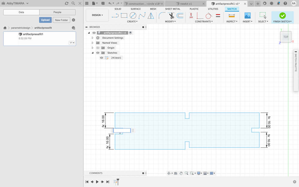
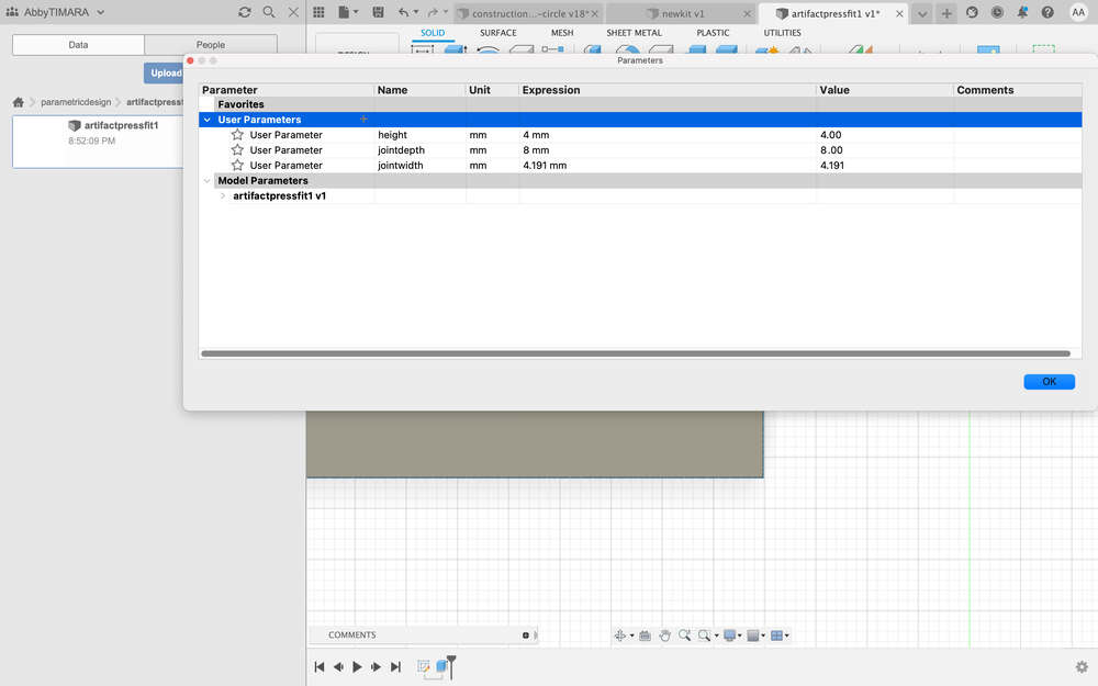
Using the spreadsheet to facilitate parametric design is relatively easy in Fusion. You simply go into the modifiers menu and choose modify parameters. You then can define variable names and values. Then, when you are defining different dimensions as you sketch in fusion you can simply reference the relevant variable name and voila, you have a design that can easily be adapted on the fly!
I began by determining the parameters I cared about, including the depth and width of the joint. Later, I added a value for chamfer and the height of the material.
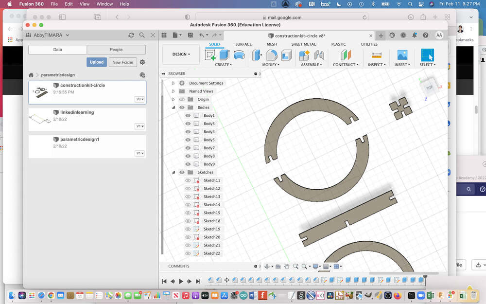
I spent a lot of time creating new sketches:
One thing I hope to improve is my organization and workflow as it relates to sketches, bodies, components, and etc. My project started to feel really disorganized and from watching a variety of tutorials I got the sense that some people design each individual part in its own file and then import them into a main file to assemble them. I hope to work towards this workflow subsequently.
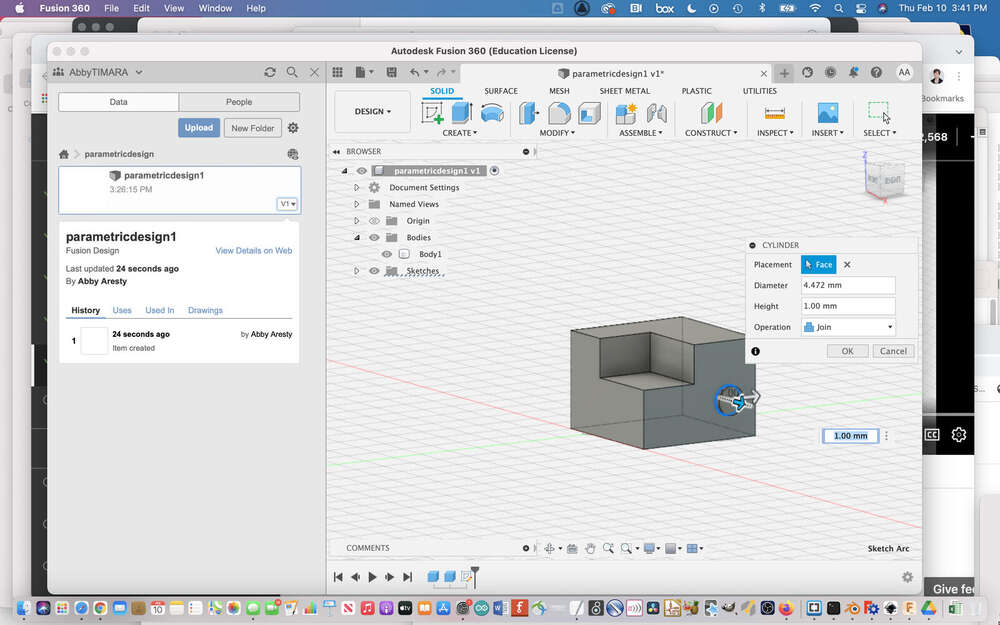
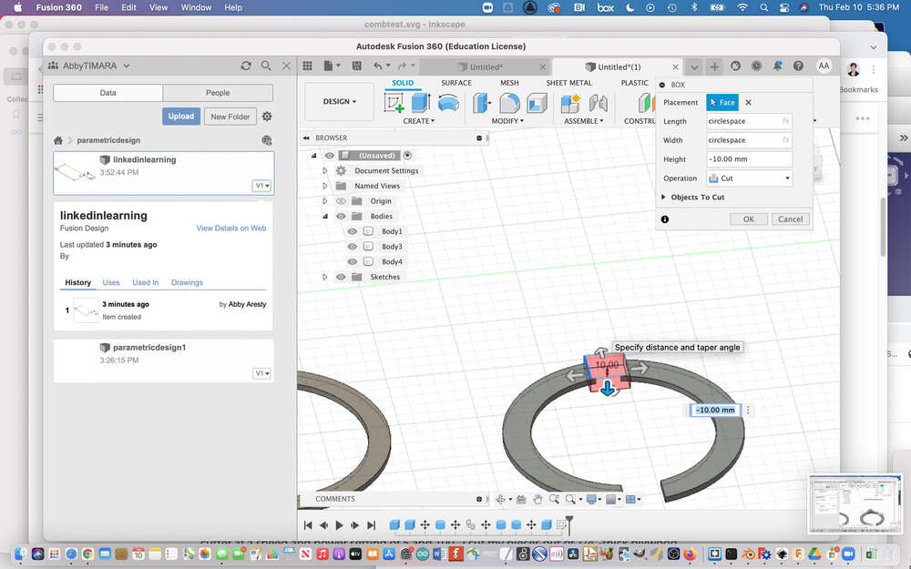
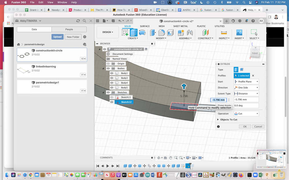
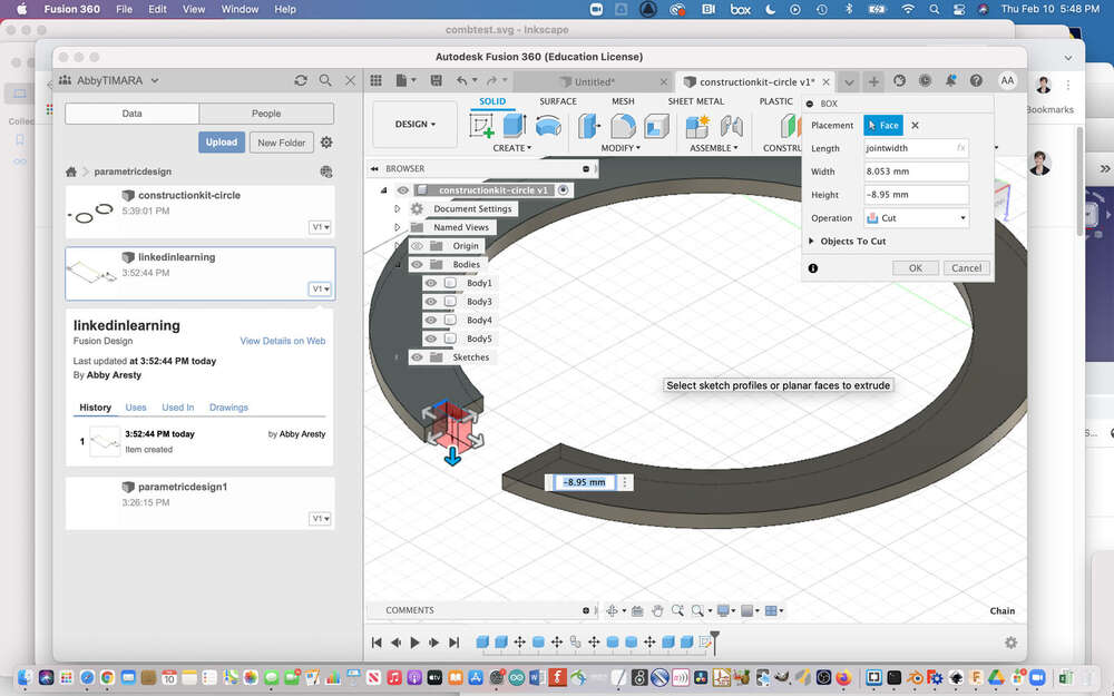
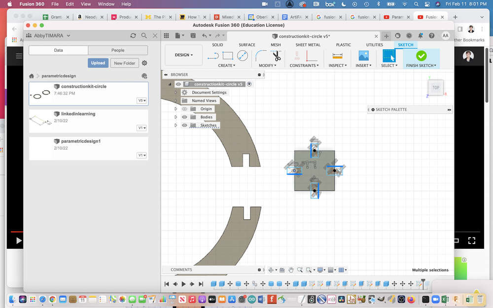
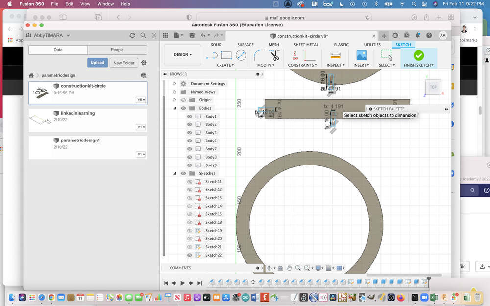
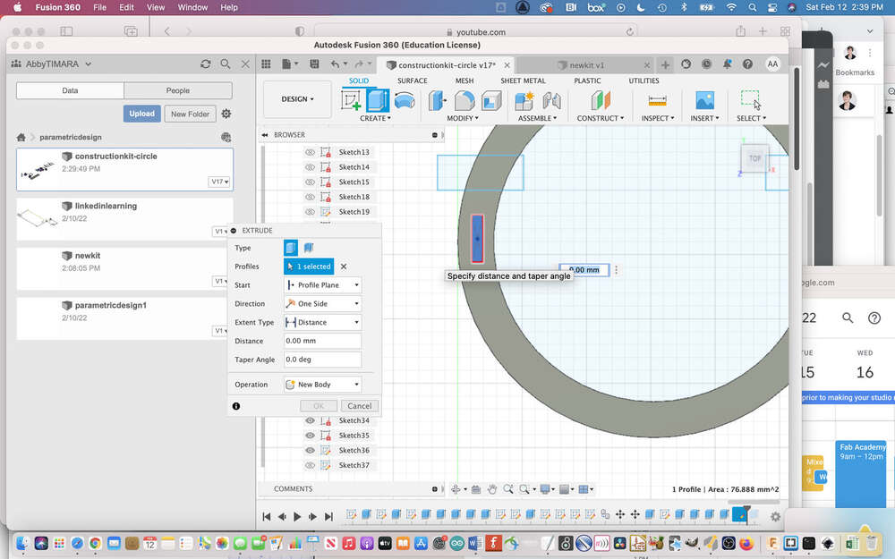
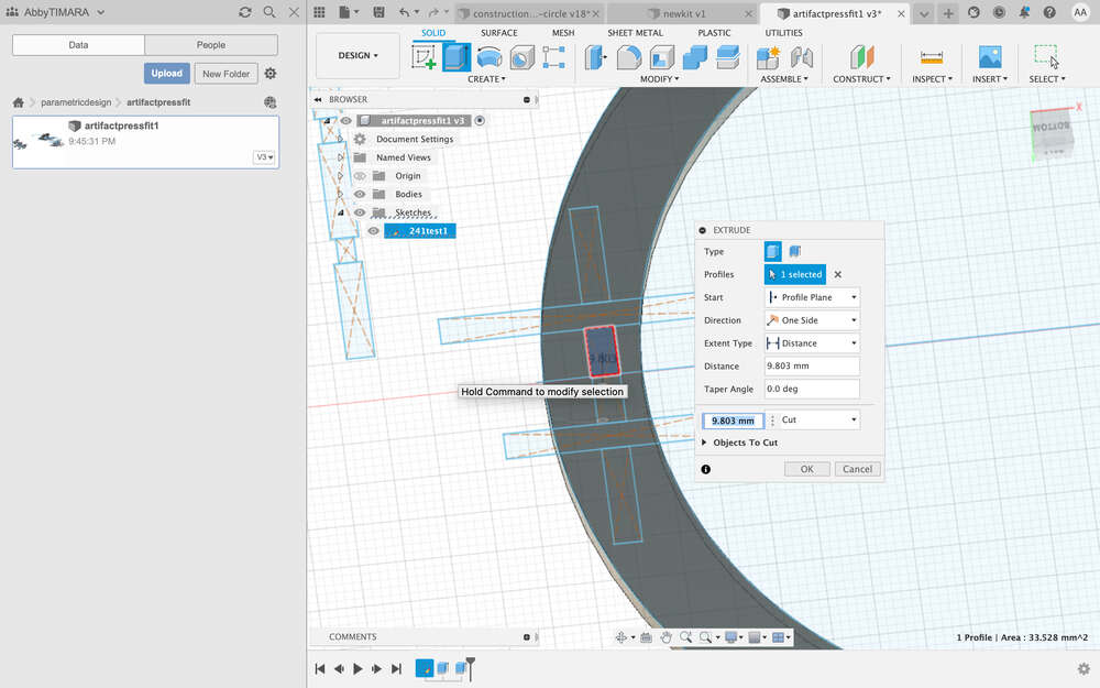
Next, I made two concentric circles, joining them and extruding the surface. I then used a box to cut the circle on both sides.
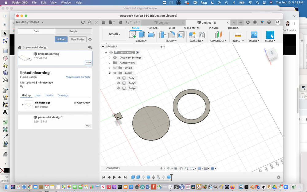
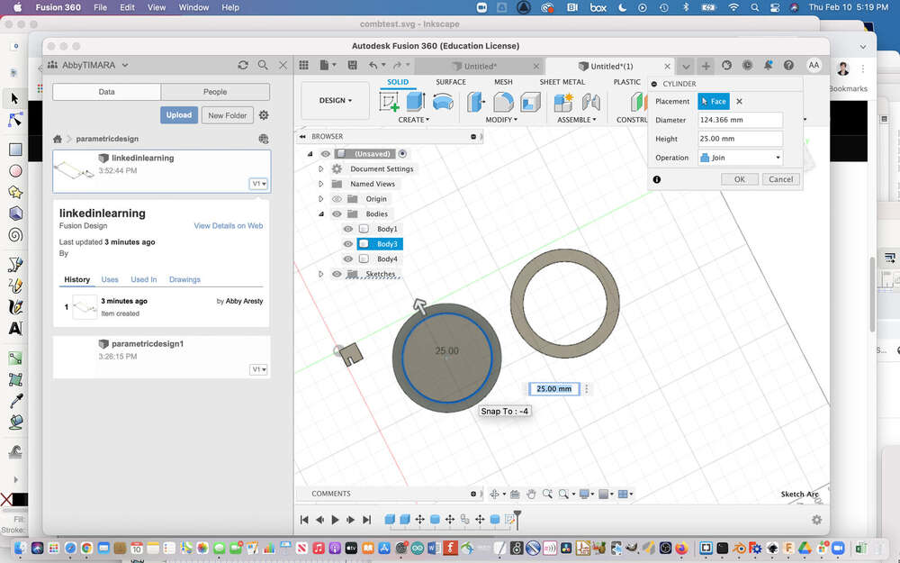
I extruded the object – but wait, that is the wrong way!
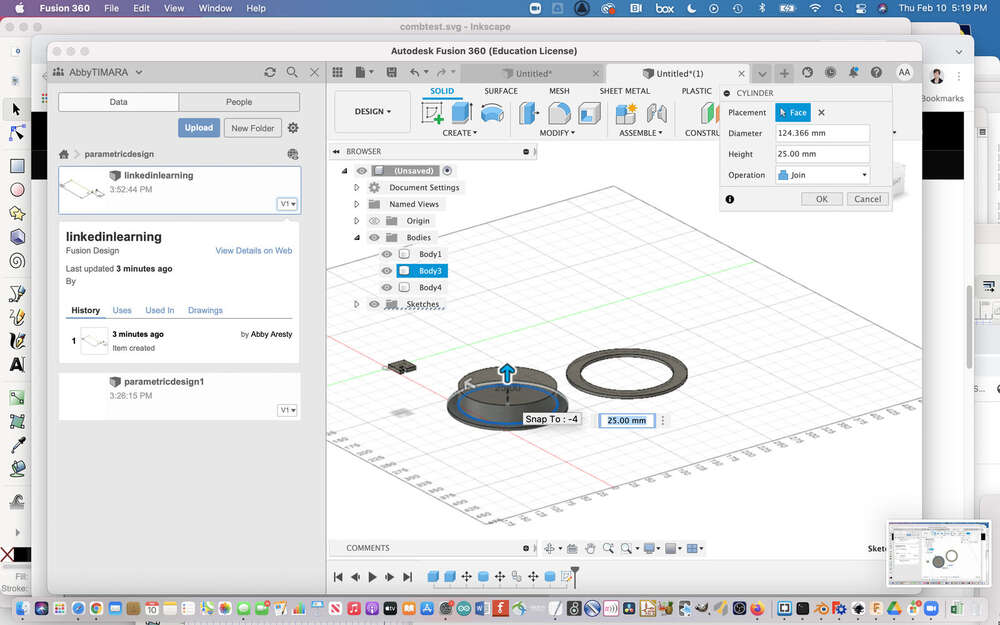
This is better:
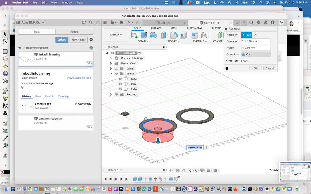
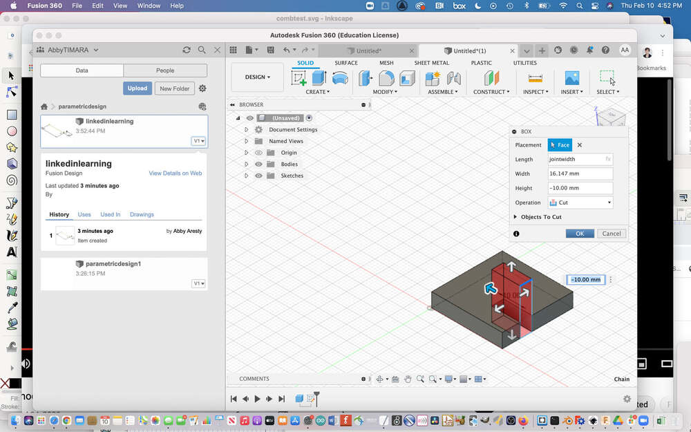
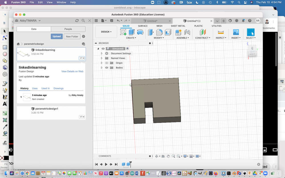
I used a square to cut the circle:
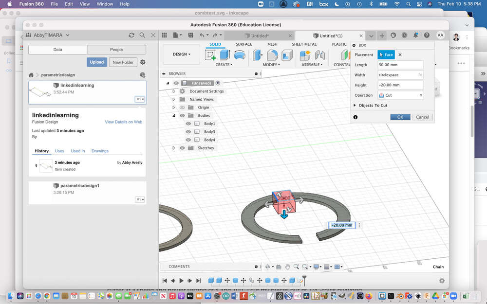
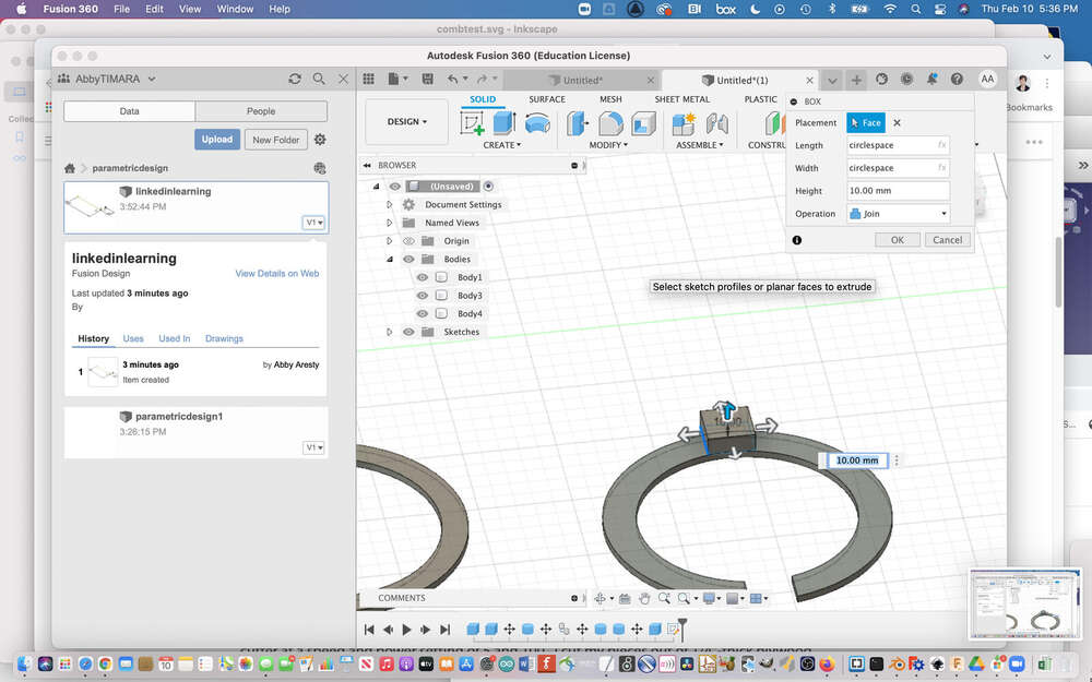
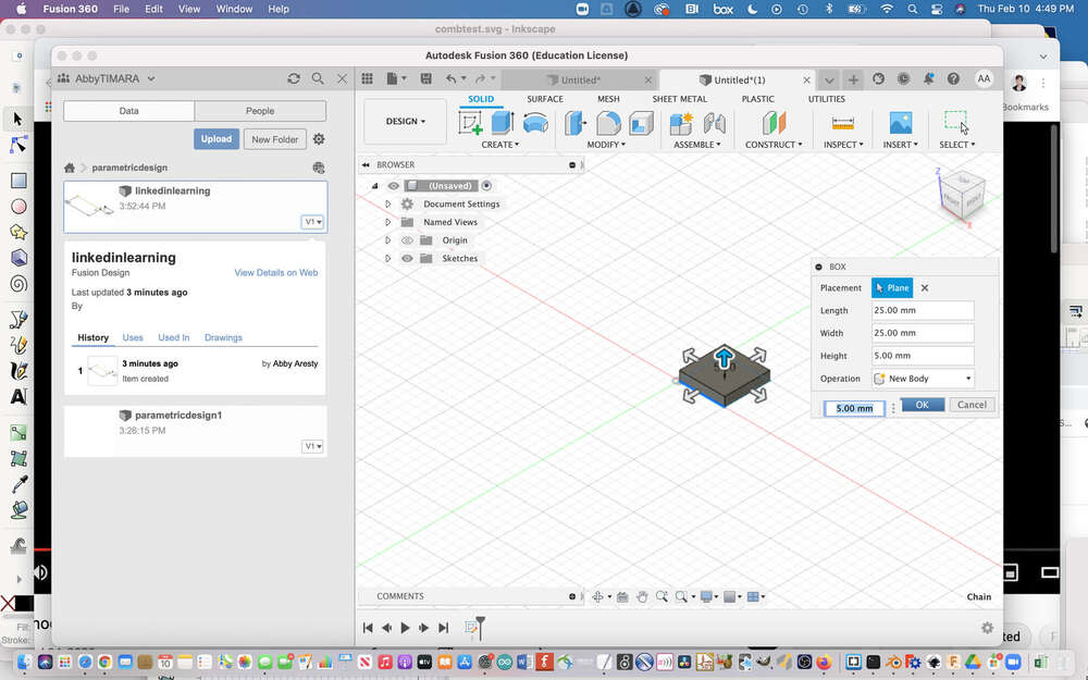
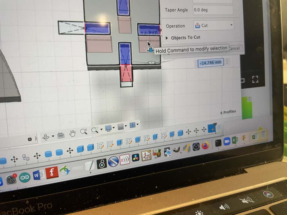
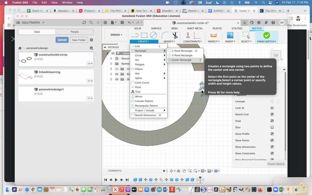
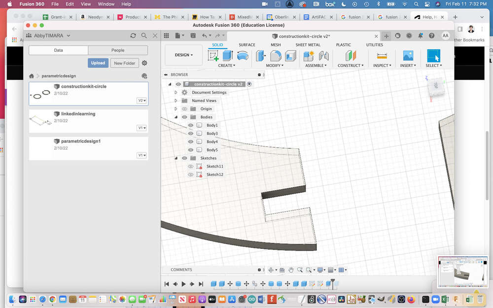
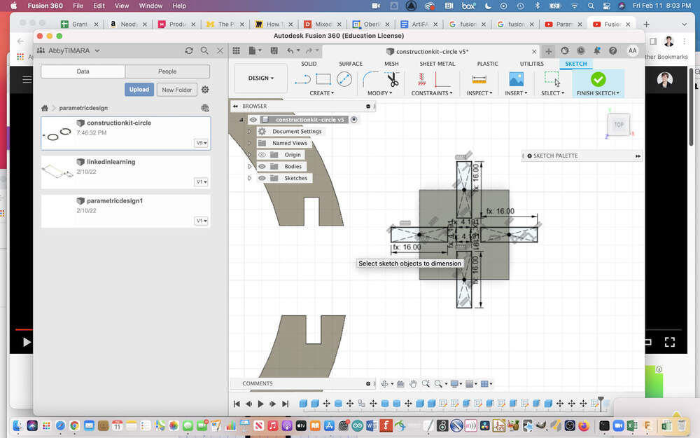
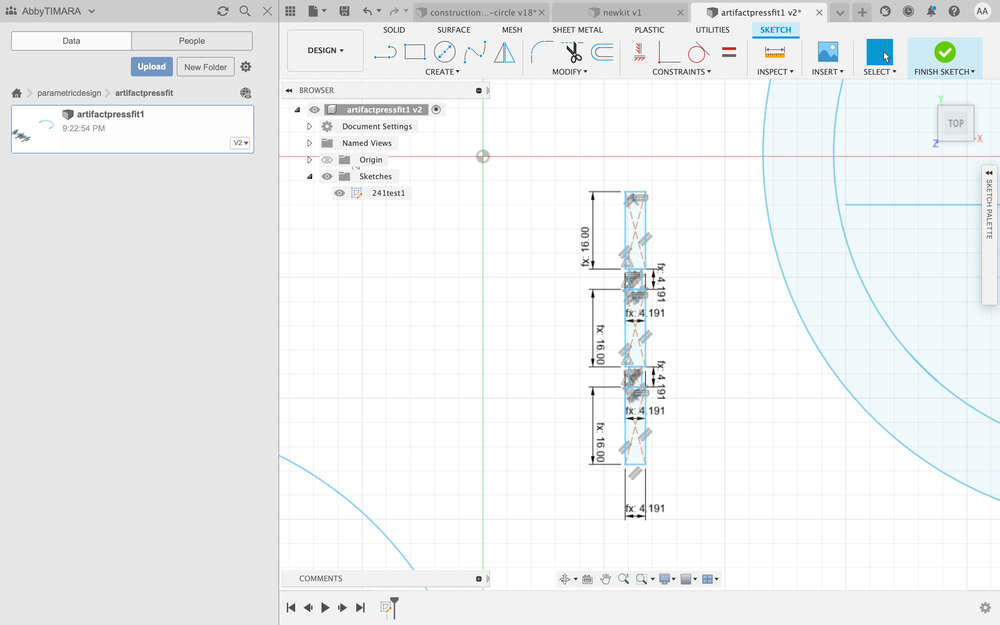
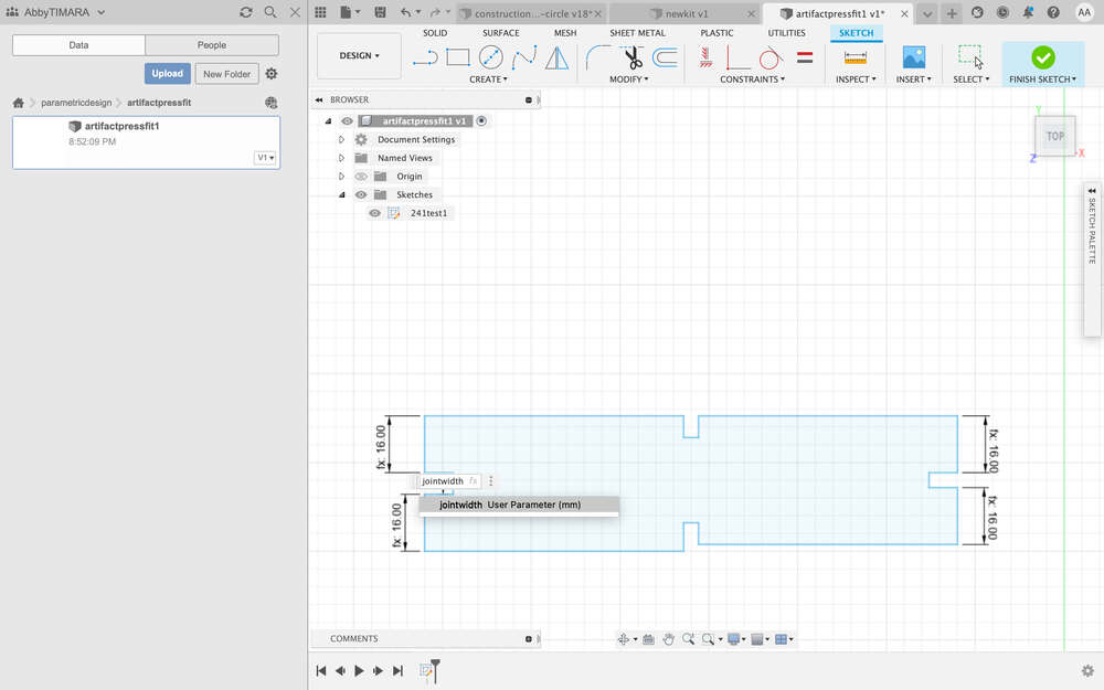
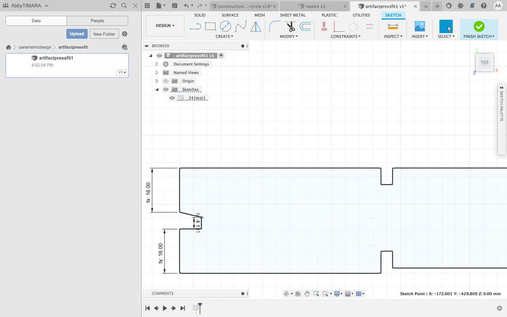
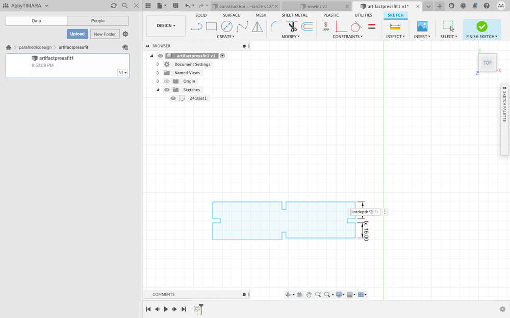
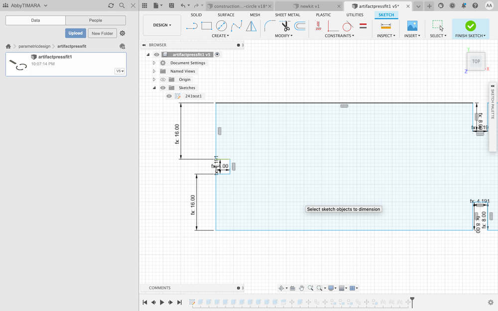
Then I created a new sketch and used center midpoint rectangles…
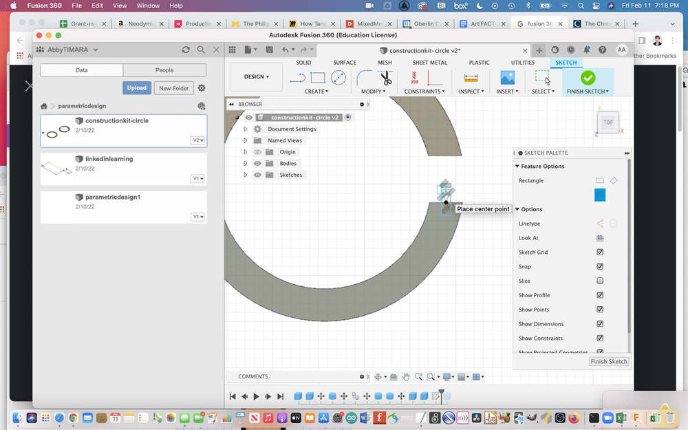
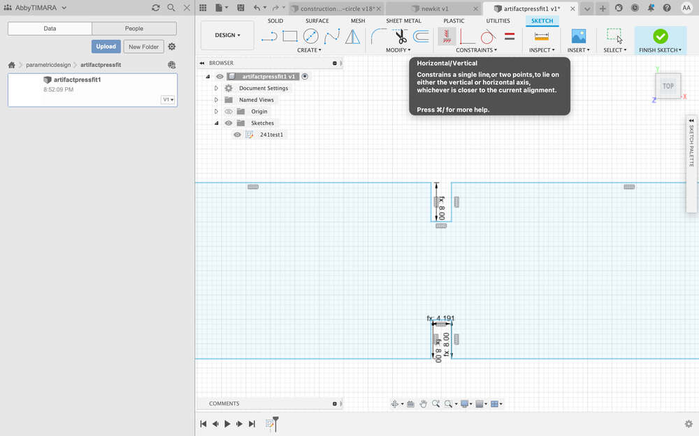
…that I sized parametrically – referring to predefined values for the joint width and jointdepth…
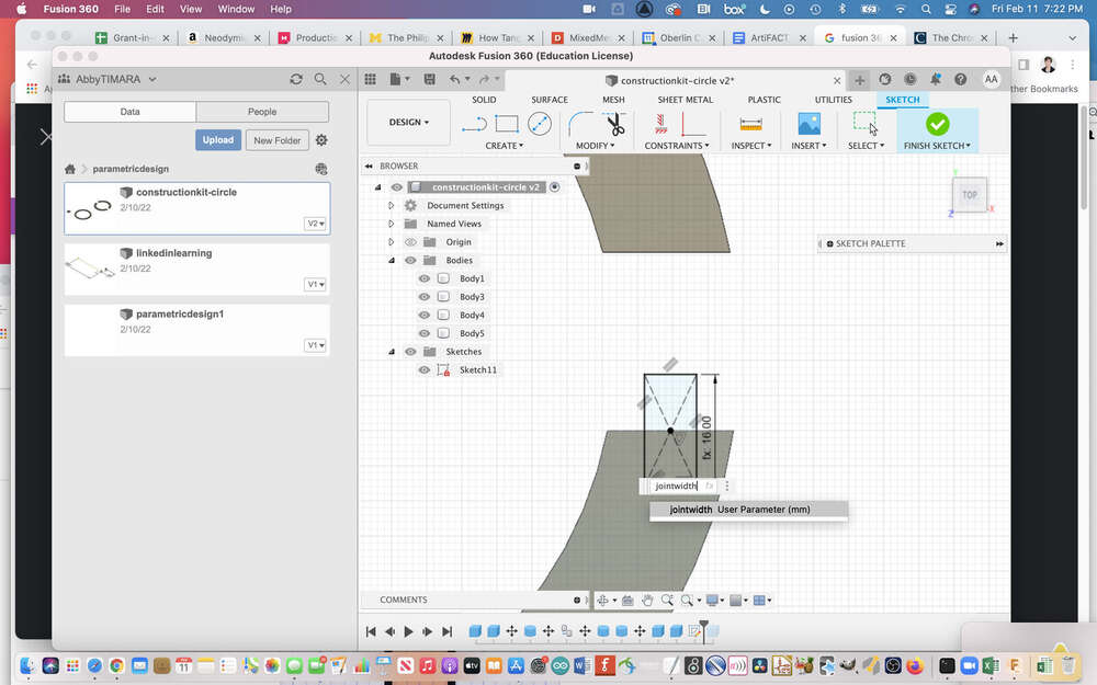
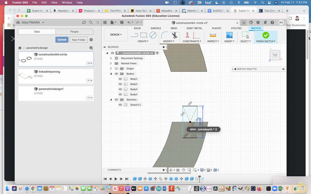
that I had set previously under modifiers > change parameters.
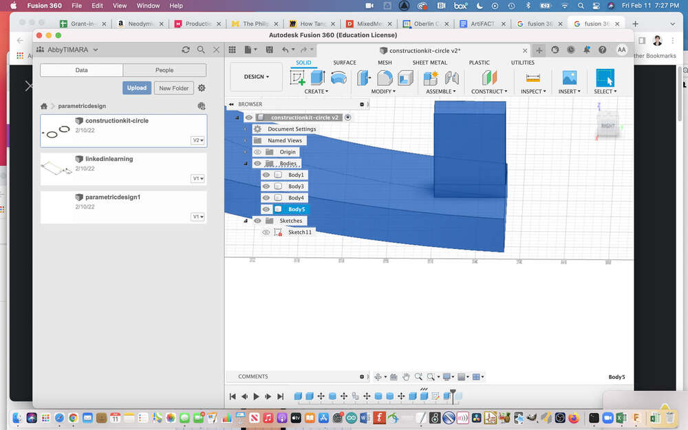
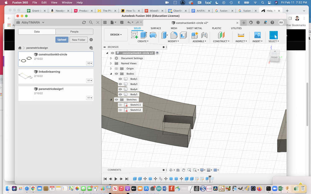
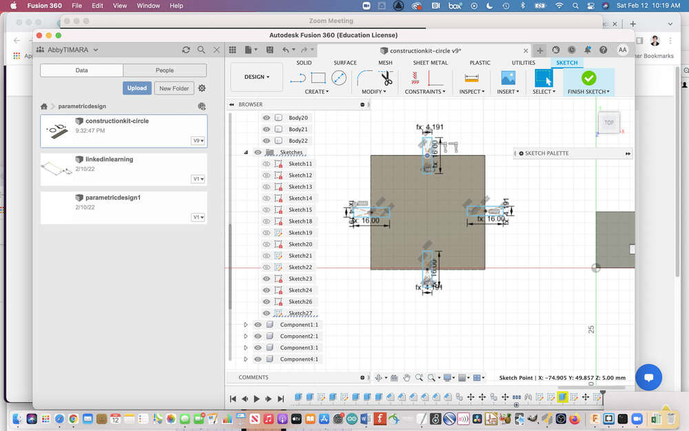
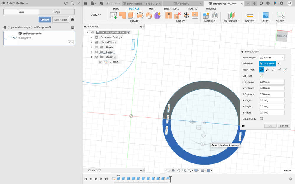
 Here is a view of the spreadsheet and the semi-circle component a bit later in the process:
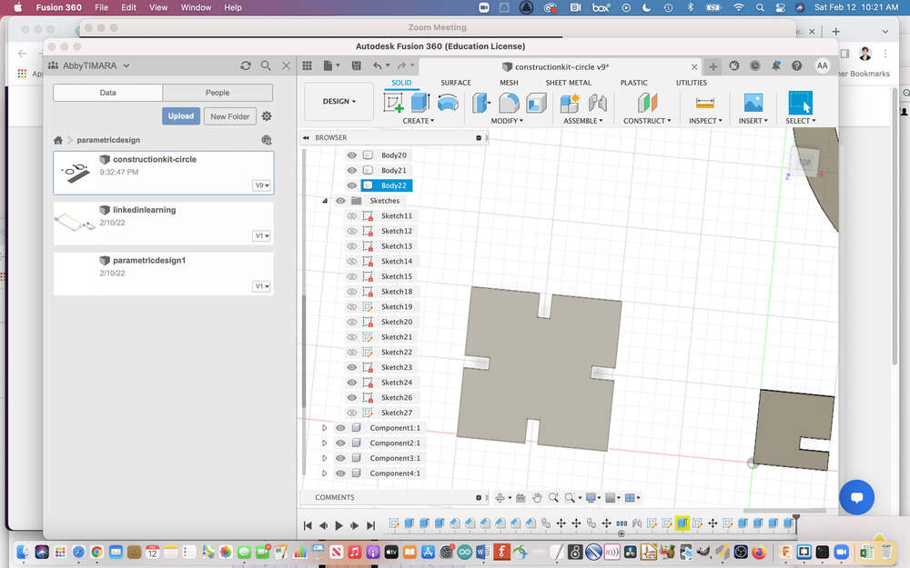
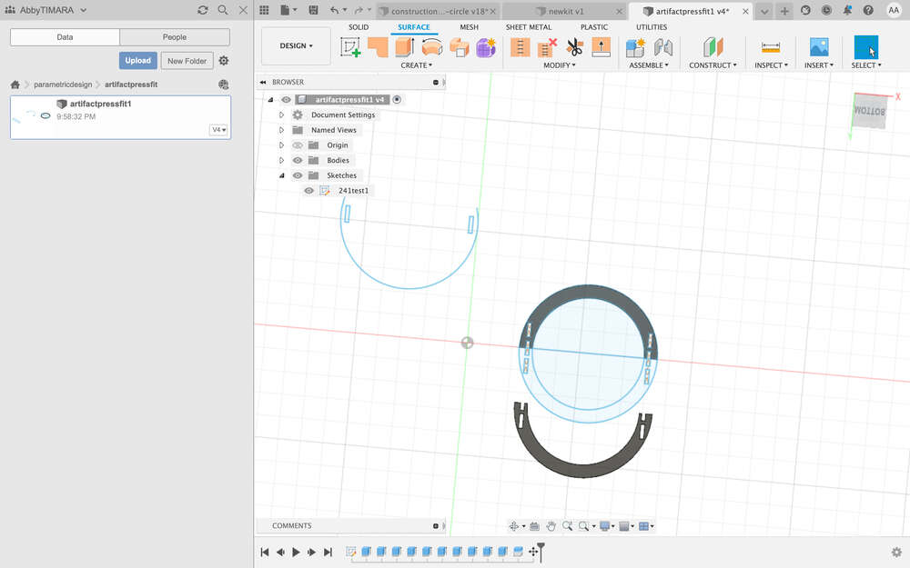
To make the semi-circle component, I made a chamfered joint:
And then extruded the object and used it to cut the semi circle:
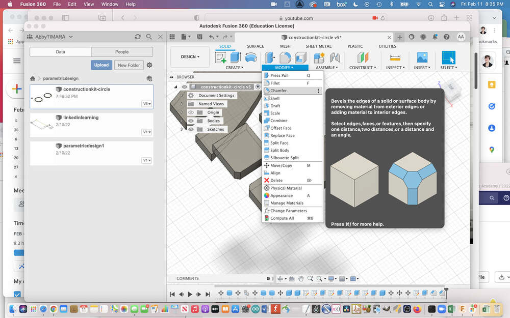
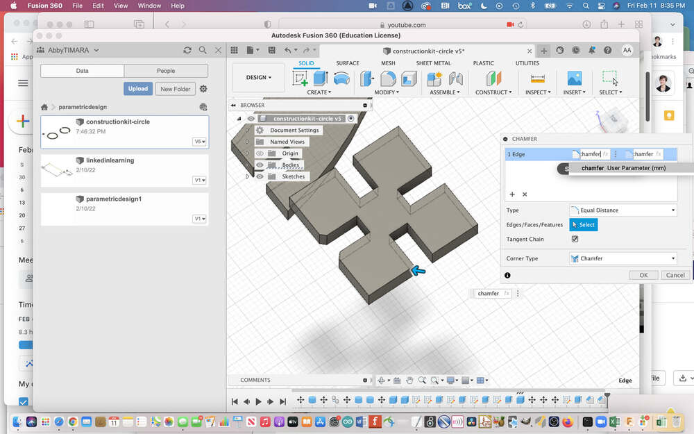
I chamfered all of the edges to make joints that would more easily fit together. You can find chamfer under the modifier dropdown menu:
You have to select the edge you want to chamfer:
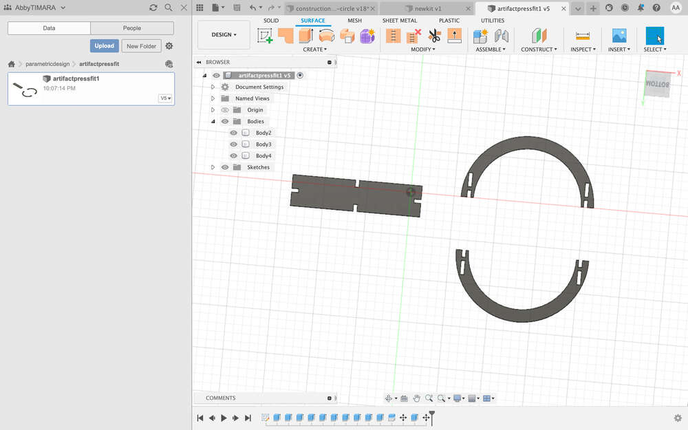
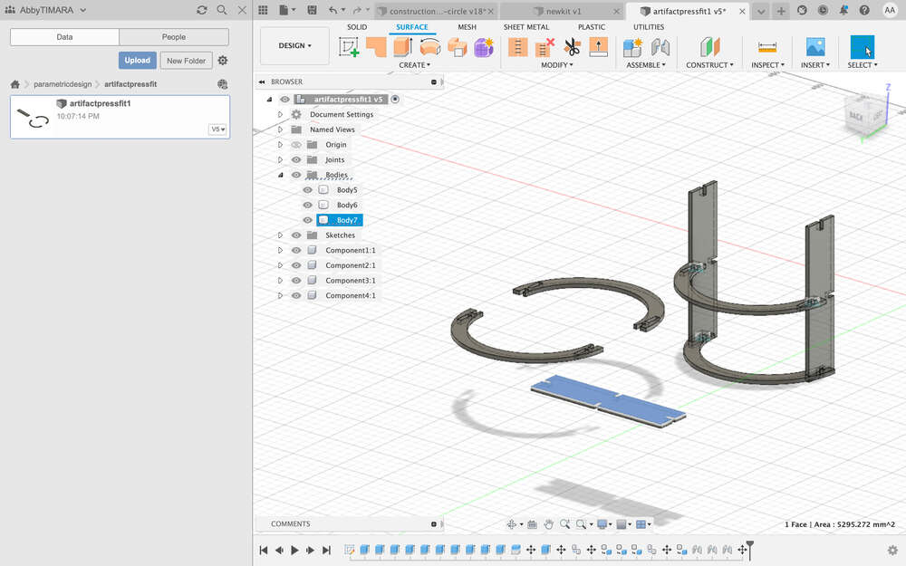
This was my first set of components:
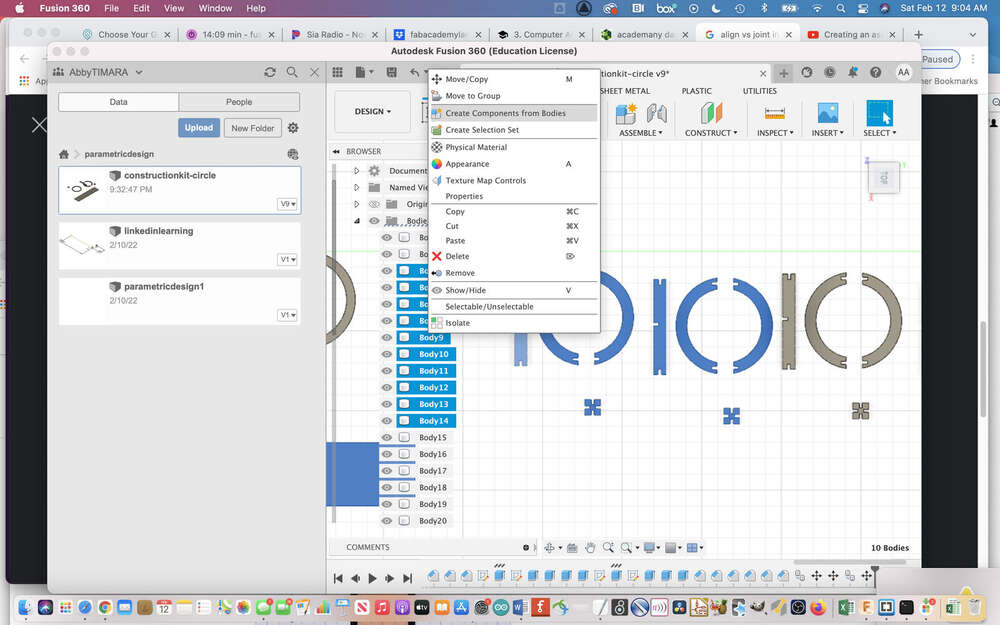
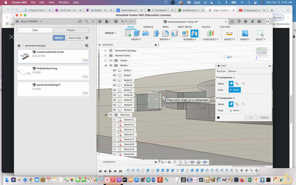
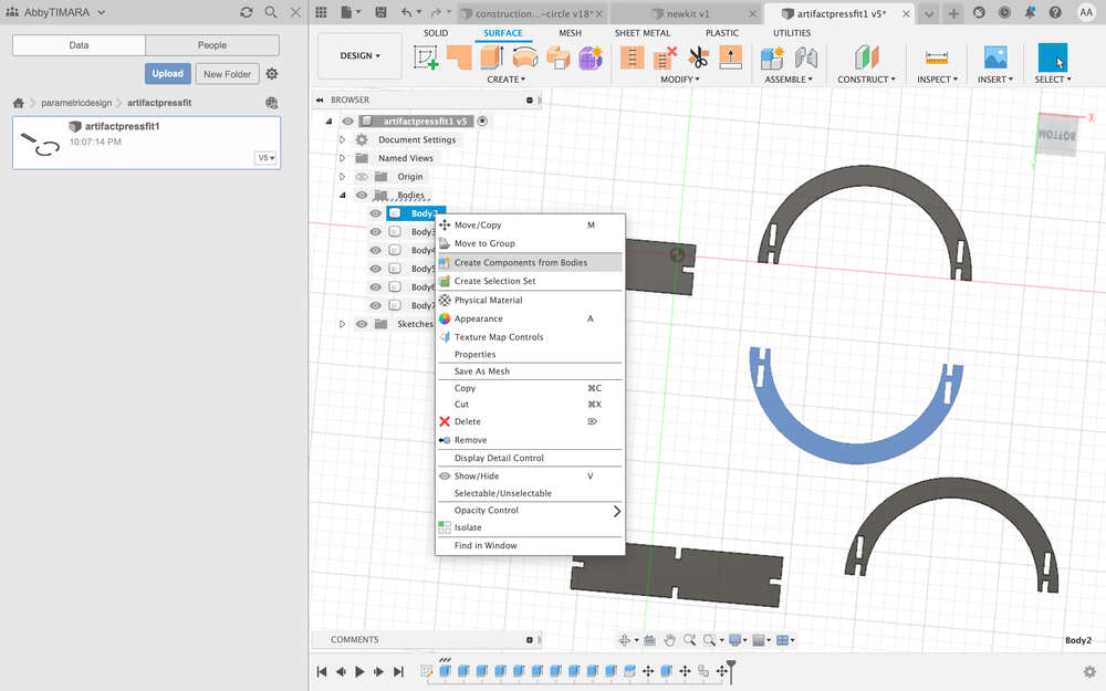
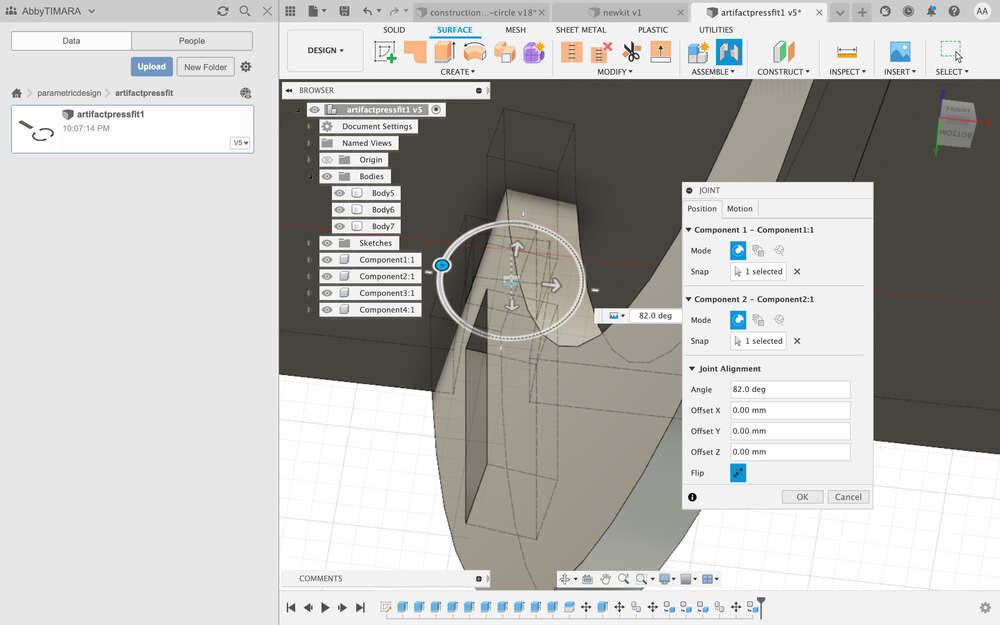
Having made the components, I tried out the joint object to assemble objects and to see how they would fit together. First I converted objects to components:
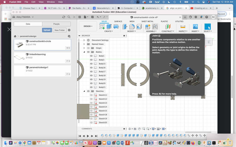
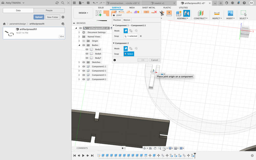
Then, using the ‘joint’ tool which is right above where it says ‘assemble’ on the right:
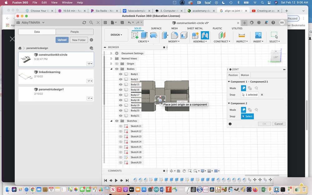
I selected the faces I wanted to join:
It ended up assembling in the wrong rotation:
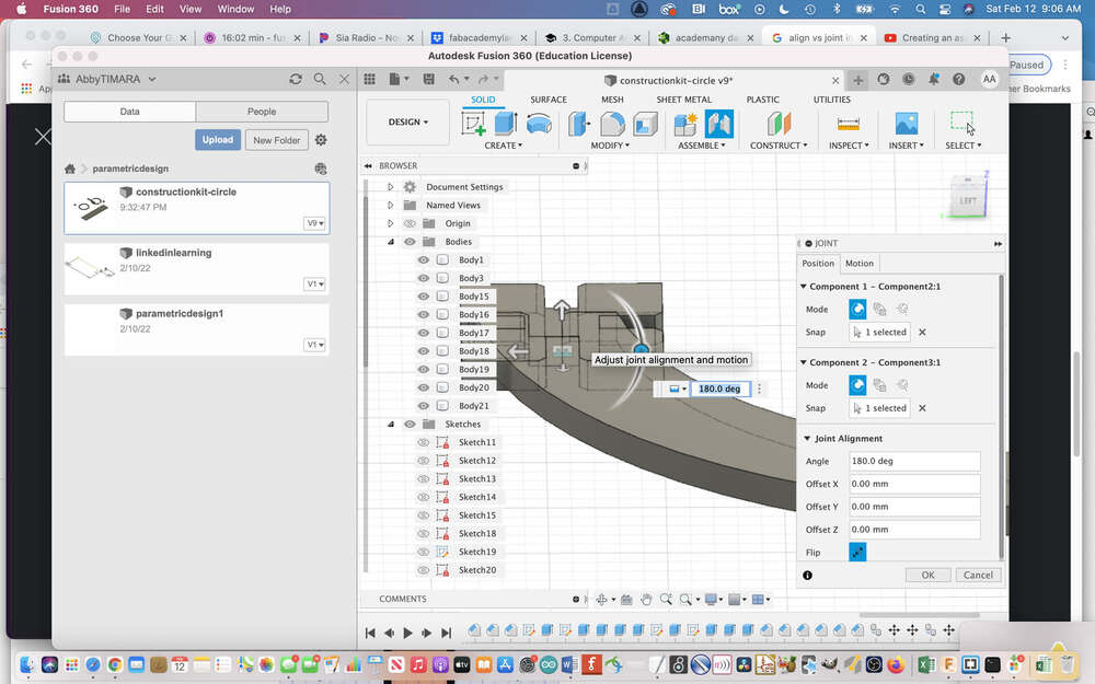
After rotating it still needed some adjustment:
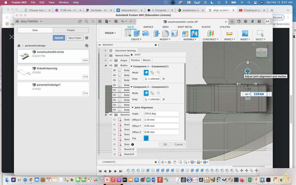
That is better:
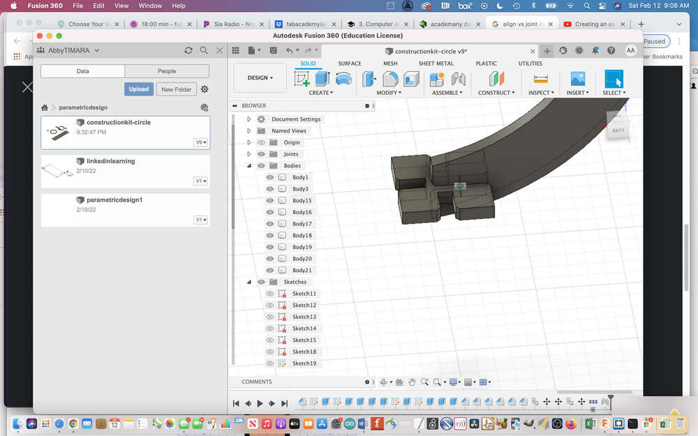
But is how I realized that the square kit component I had created was too small…it does not account for the depth of the joints in the other kit components:
So I made a bigger square connector.
To make the notches, I used the center point rectangle which you can find in sketch mode under create rectangle.
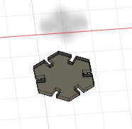
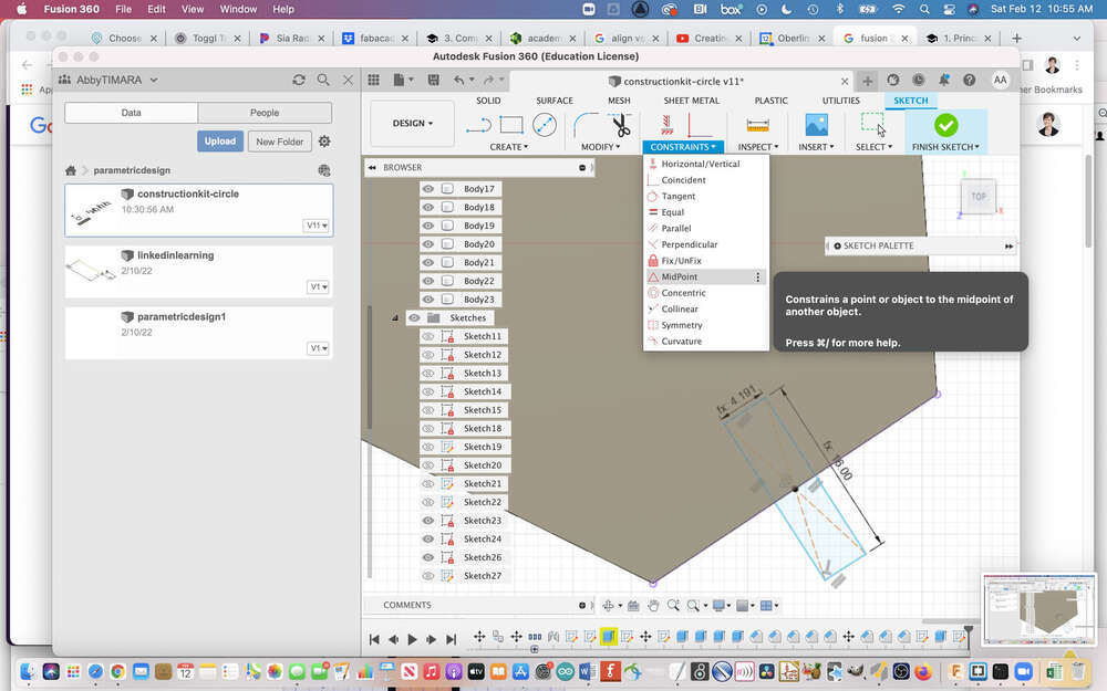
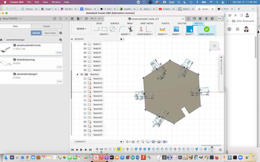
For good measure, I also made a hexagon connector:
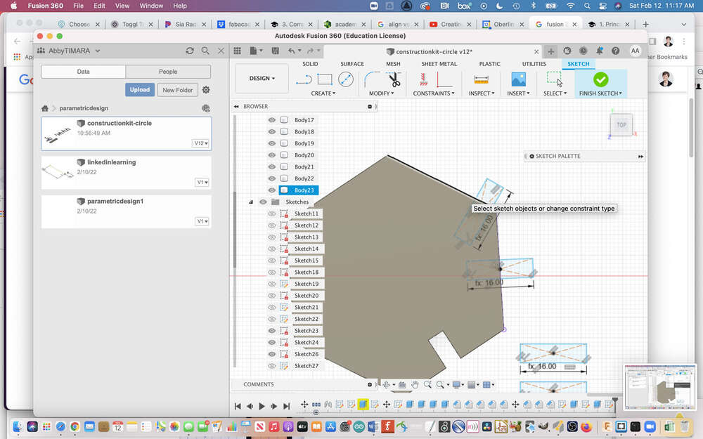
This is when I learned about the midpoint constraint, which I had been searching for for awhile - hooray!
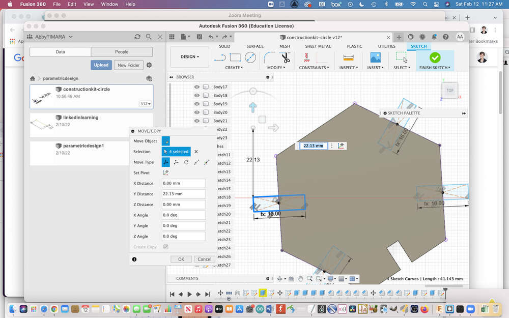
After attending the parametric design recitation, I realized I should have just been making triangles around a circular path…this would have saved a lot of time! Oh well, live and learn.
This helped me to align all of the joint notches correctly.
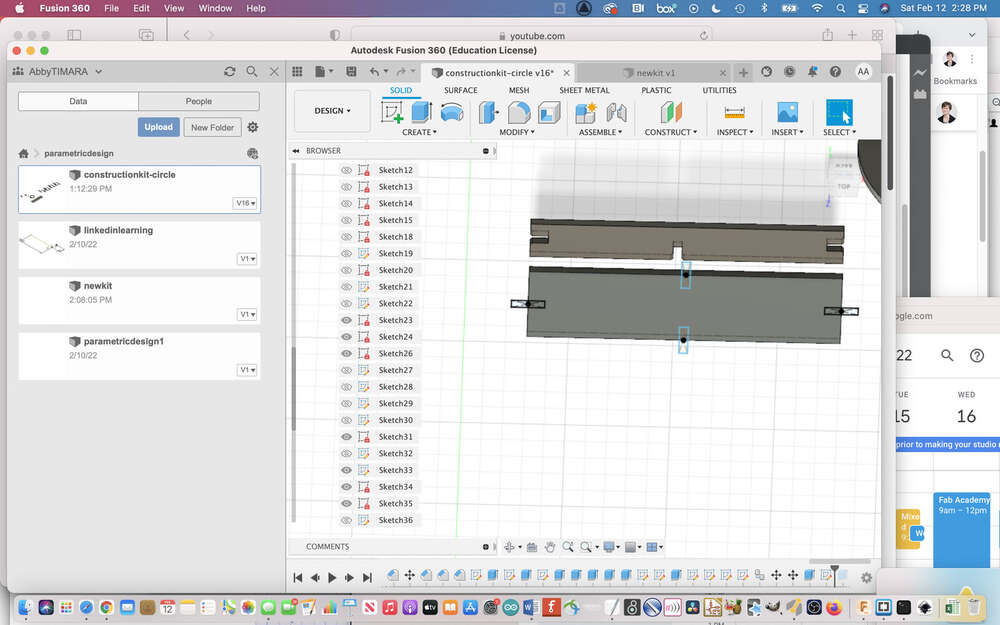
Initially, I made a single long thin piece that I hoped I could use as a frame of sorts:
Later, I tried making a wider long connector with notches on both sides that I thought might be more flexible.
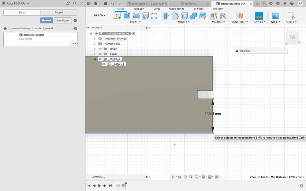
I thought about making a different type of joint–essentially just a hole–to allow me to connect a semi-circle at the top of my kit…I used the inspector measurment too:
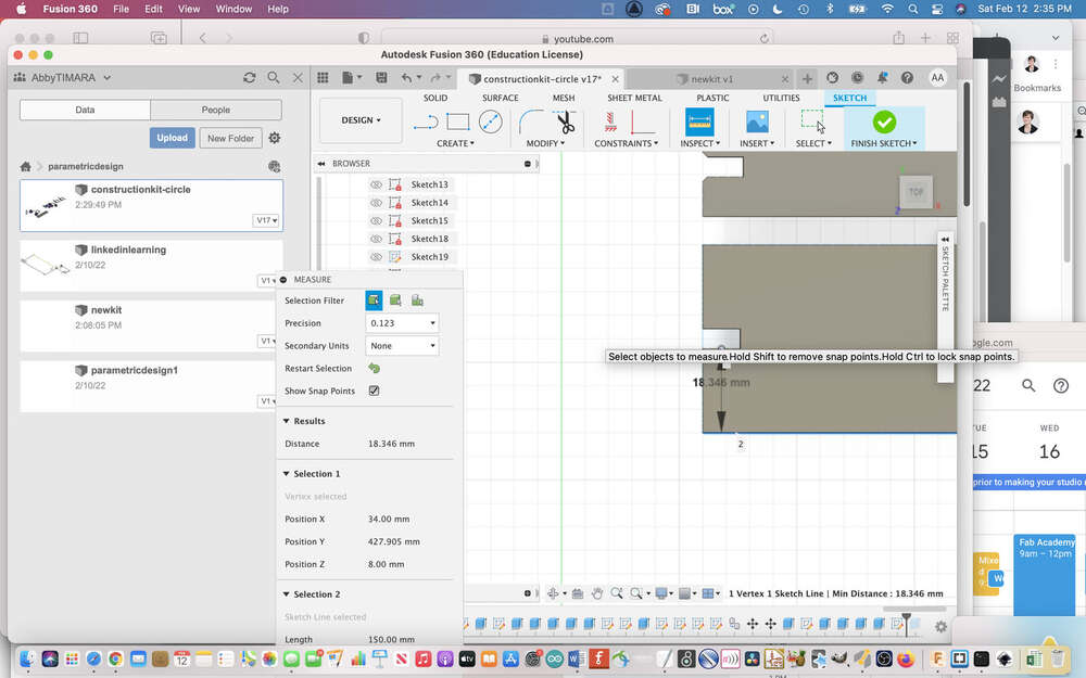
I made a semi circle with a hole to connect to the top of the long frame:
Here is the second prototype of kit components I designed:
Compare this to sketches of the first set of parts – I originally planned on many more components:
Laser Cutting
We learned about laser safety during the global session on Wednesday. The biggest single takeaway was to never leave the laser cutter unattended. A second takeaway was to be very careful about the materials you are cutting, since some can release toxic fumes.
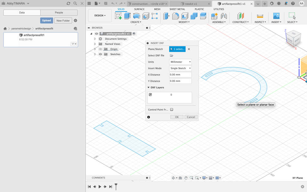
With this in mind, I cut a first set of components at LCCC on Saturday. I learned the process to go from Fusion to CorelDraw to make the cut. Unfortunately, I didn’t save the video I watched and I can’t find it now…I was rushing to get things done within lab hours so I did not do as good a job documenting as I went! In any case, the steps involved selecting the relevant faces of objects I wanted to export, hitting p to pull up the project menu, exporting a sketch, and then exporting to DXF. I know Neil said DXF is not ideal, but others locally have said it is fine for this purpose.
Here are some photos from using the laser cutter at LCCC:
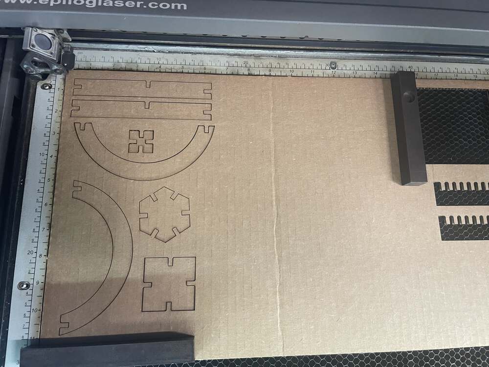
Based on the components I made, I determined that:
- I needed my press fit semicircle to have both a notch and a hole
- The square and hexagon components were not going to be particularly useful for what I wanted to do.
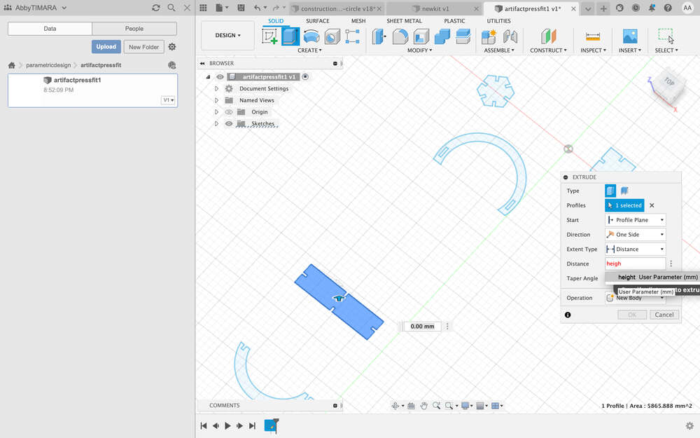
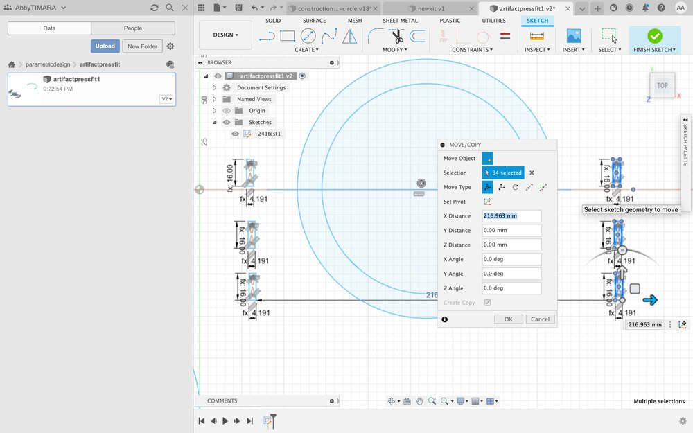
I set about creating a new set of components in Fusion. Here I am making the rectangles parametrically that I will use for the joints:
You can see them next to and then atop the semicircles in which they will be placed:
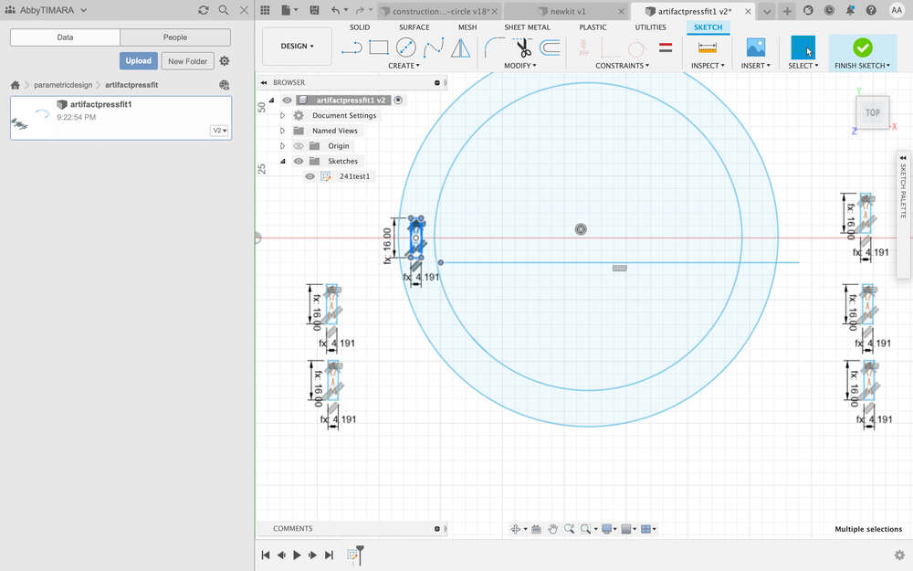
Next I worked on aligning these rectangles on the semicircles in preparation for using them to cut the body of the components.
Here are the semicircles, almost ready for action:
Here you can see what the component looks like:
When I was working on creating the larger straight piece for the kit parametrically, I ran into some issues related to the constraints that needed to be in place. As a result, I got some funky unexpected shapes, with some parts longer or wider than others:
And the occasional angle issue:
So I worked on adding some other constraints to solve the problem:
I also took some measurements to help decide whether I wanted to add parametric dimensions to other parts of the sketch.
And I decided to constrain the width of this component to be 2x the jointdepth variable.
Here are some of the finished parts:
To assemble the objects using the joint tool, you have to make them into components:
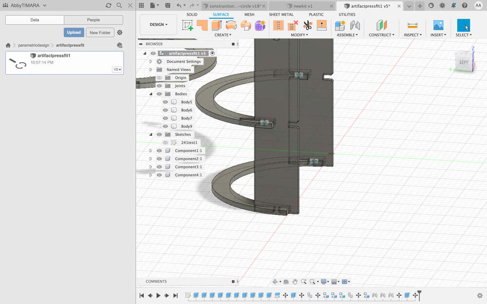
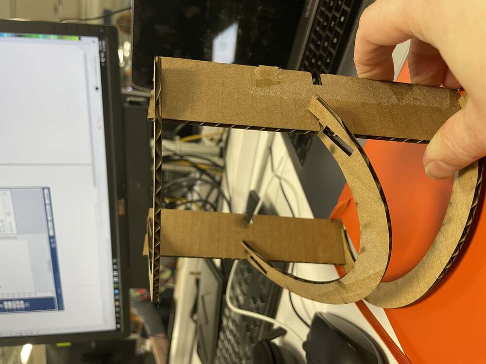
You can then use the joint tool to select the faces that should connect:
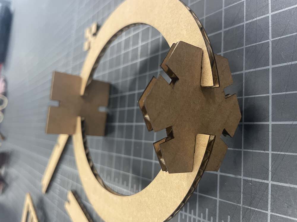
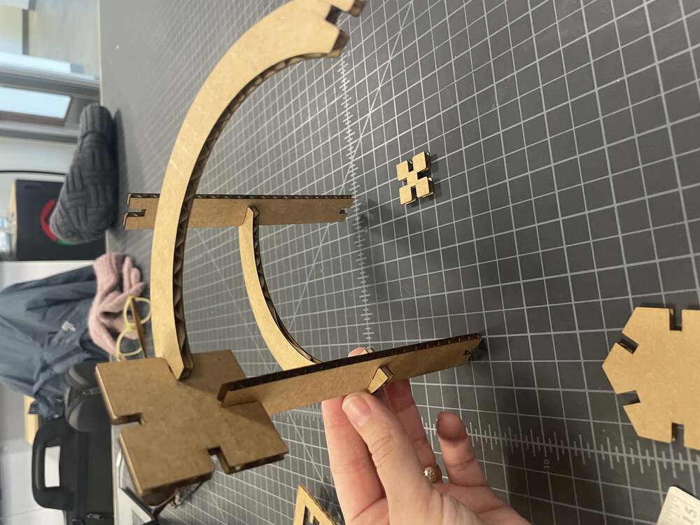
Here you can start to see what the kit might look like assembled.
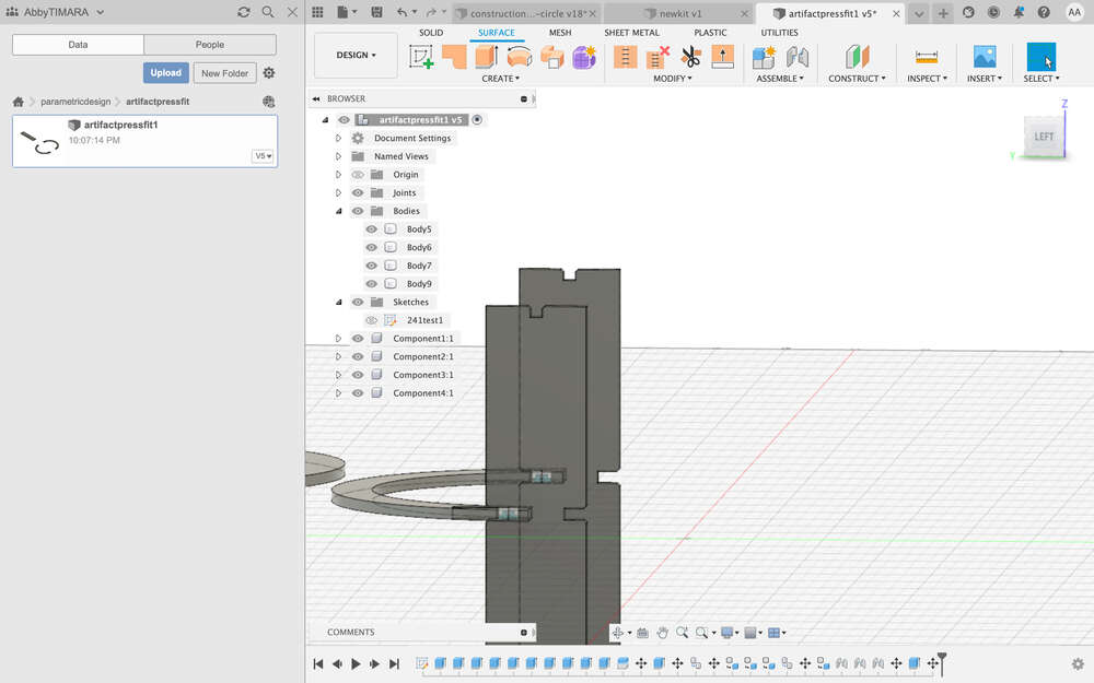
Here is a close up of one of the joints:
There are several issues…one is that instead of having a hole joint in the semicircle, I think I need some sort of snap-through pass.
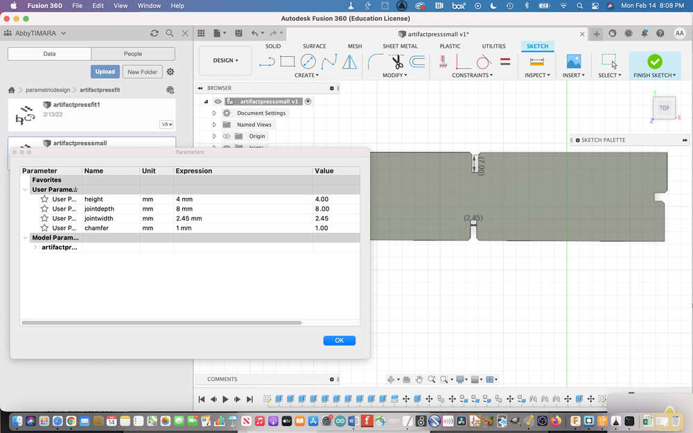
I was very glad that I had made my design parametrically because when it came time to cut my third prototype, I had to use different, much thinner cardboard. So, all I had to do was edit my spreadsheet and everything adjusted automatically!
Although, as you can see, I must have made a mistake somewhere because one edge of my part was longer than the others. I wish I could say I solved this, but the clock was ticking and I had to get the part cut before I had to leave the Fab Lab so I just called it good enough for now.
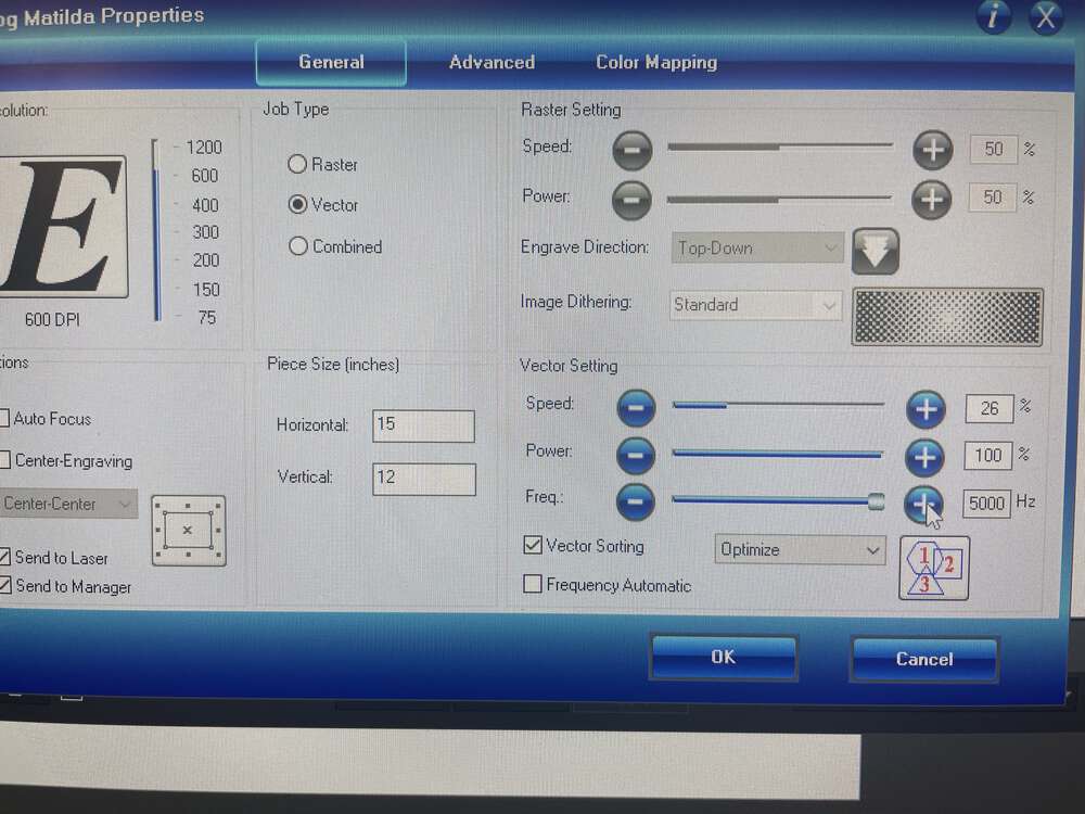
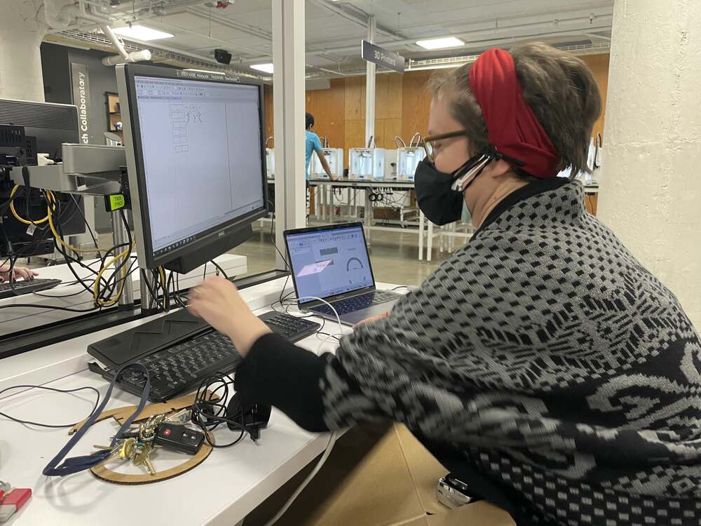
Here I am at Think[box] preparing files with the proper settings.
They have a spreadsheet with many different material types. I was instructed to use the setting for ‘mat board’.
I was excited to try out the gigantiic lasercutters at Think[box]
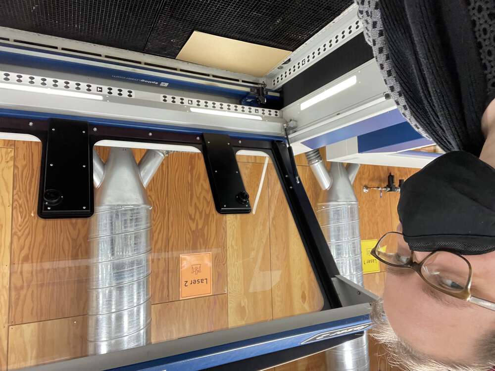
The controls are fancy but the process is similar…you need to double check that the size of your proposed cut fits on your material. You also need to use the autofocus magnetic key, letting it dangle and just touch the surface of your material, adjusting the bed until it is right, before removing the focus key and setting up the machine to cut.
Hit play to watch it go:
And weep when you realize you forgot to actually measure your new cardboard and adjust the settings in your design.
Make a new comb super fast – this time, parametrically in Fusion
And make a kit that fits together better! Not perfect, but definitely an improvement.
Lessons Learned
One thing that I learned this week is that the process of moving from a file you have prepared to actually being able to cut the file in a laser cutter takes time. Sometimes it takes a lot of time, particularly if it is a newer process. Because of my day job, I’m somewhat limited in the time I can spend in the lab. I wasn’t happy with where I had left off on Saturday. I knew I wasn’t going to be able to get back to LCCC during open hours before Wednesday so I decided to visit another local makerspace, the Think[box] where a friend of mine works. I thought I would be able to do several different things at the Think[box] but at the end of the day, I was rushing just to get my updated files cut, because it took me too much time to transfer them over and to get the new width on the different cardboard I was using.
I also learned how important the details are in fabricating objects and how helpful prototyping is to making errors and potential issues clear. I’m glad to have had a chance to do some prototyping this week and have ideas and plans for next steps!
Vinyl cutting with a consumer craft cutter
While many labs are equipped with large industrial vinyl cutters like those manufactured by Roland, my experience is with consumer-grade craft cutting machines like the Silhouette Cameo and the Cricut Maker. These machines are amazingly versatile. You can use them to cut vinyl, paper, craft foam, some fabrics, and copper tape, among many other materials. You can also use them to assist with processes ranging from making vinyl decals, to screen printing, to making temporary tattoos, foiling, drawing, and much more.
What is all the hype?
I purchased a Sihouette Cameo 3 for my department in Fall 2019. For the next couple of years, this machine – along with a Cameo 4 I purchased for myself later that year – was the only digital fabrication tool we had on site. I had to go across campus to use a 3D printer, and to LCCC to use a laser cutter. As a result, my students and I spent a lot of time experimenting with pushing the limits of our machine. We used the machine for class labs, for community-engaged work, and various creative projects.
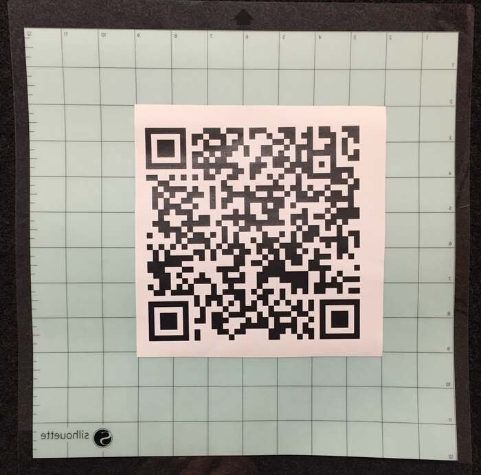
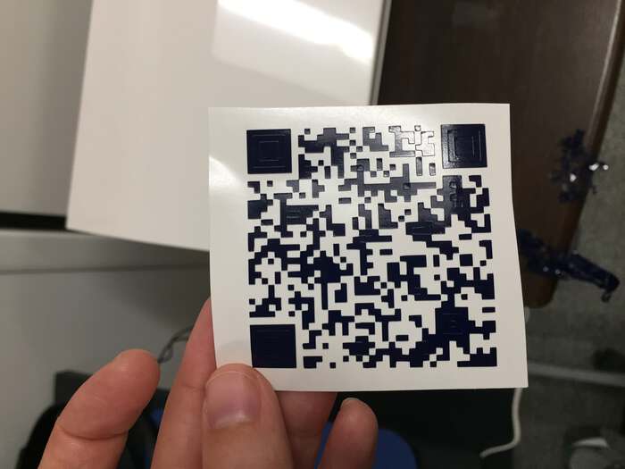
For example, I taught a class on Reimagining Maker Cultures in which an early lab involved the collaborative development of a ‘rare meme’ collection, featuring geo-located memes accessed through vinyl-cut QR codes.
Here is the Silhouette file of an example QR code I made for my students. No meme here, sadly, just a photo of myself in the TIMARA studios:
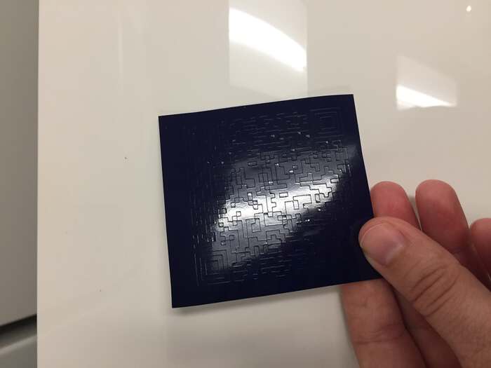
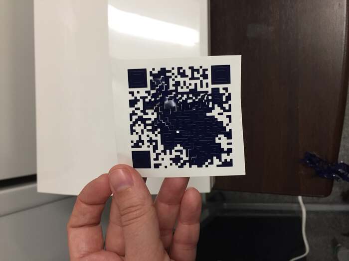
Here, the QR code after I cut it but before I weeded it:
Weeding the qr code:
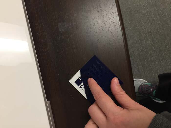
After removing the first pass:
Parially weeded QR code:
Fully weeded QR code:

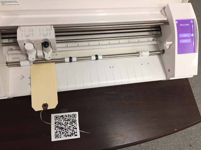
We added tea-stained ‘rare meme’ tags that we printed in the letterpress studio. This is a blank tag without any printed materials, but it gives you the idea:
I will say that weeding this test QR code went very smoothly. When I subsequently invited students to create and weed their own QR codes, the results were very mixed. It took some folks an inordinate amount of time to complete this task…so, I have never assigned this particularly project since.
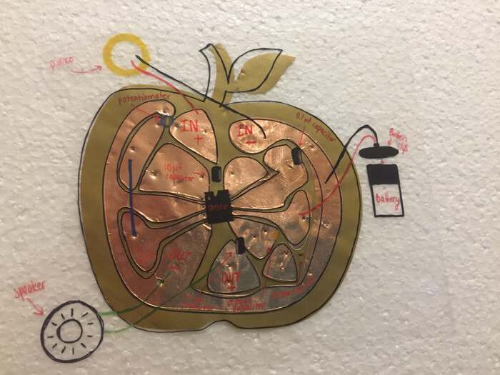
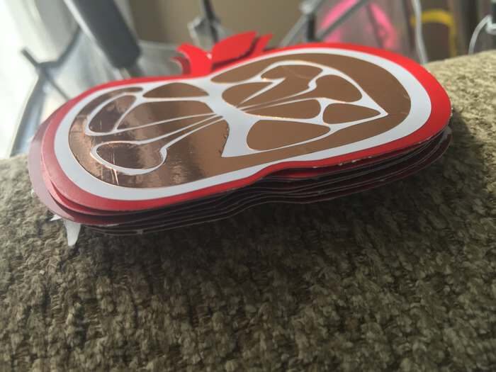
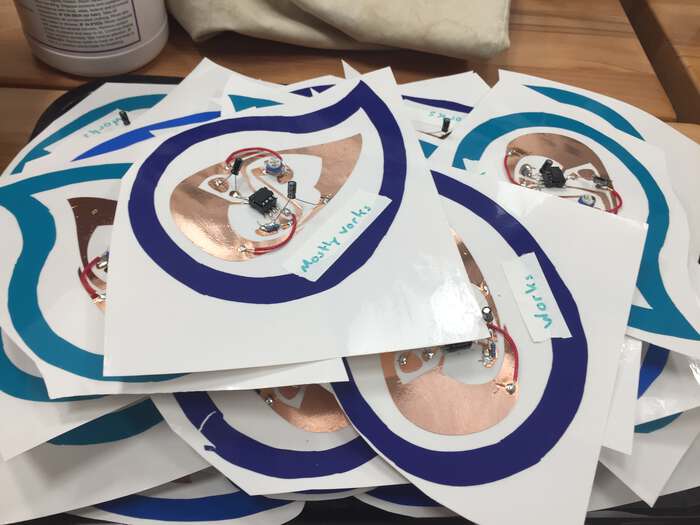
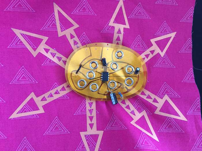
Later, we used the craft cutter to cut copper tape circuits like the Apple Amp and Orange Synth, both designed around an LM386 Op-Amp chip:
Apple amp with circuit. The wonderful illustration overlay is by Rachel Gibson:
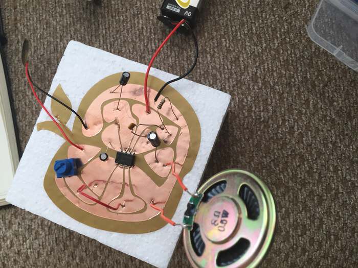
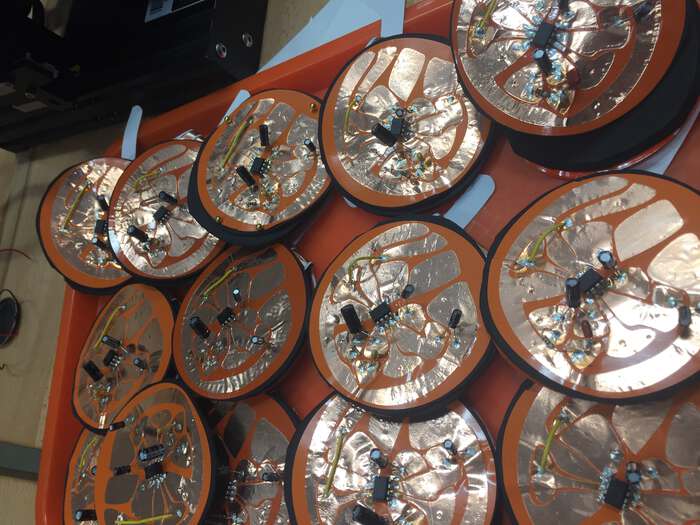
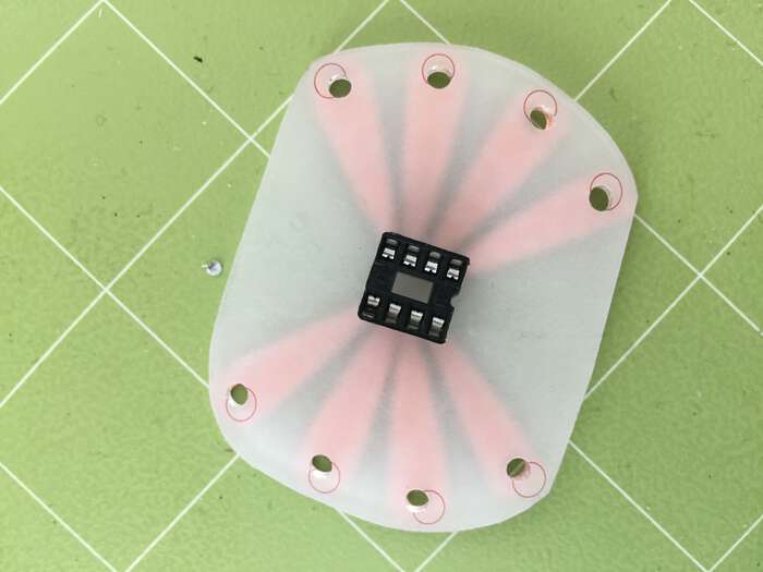
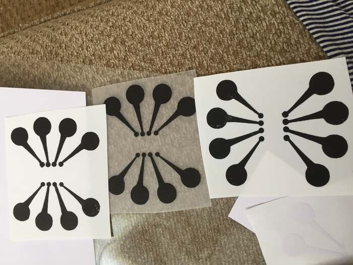
Apple amp substrate and traces, getting ready to get boxed up in kits for campers:
Orange Synth:
Thanks to Rachel Gibson for making this excellent documentation of how to make an orange synth:
Here are some of its squeaky sounds:
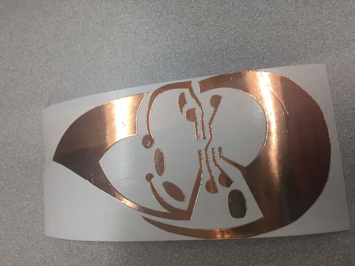
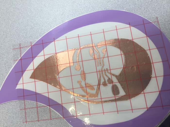
We made a raindrop-shaped circuit using a 555-timer chip to make soft (solar-powered) dripping sounds.
raindrop design
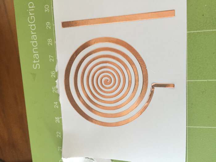
We also cut copper spirals to serve as electromagnets in paper speaker designs:
We cut copper fabric with a heat n’ bond backing that allowed us to iron it down to a separate piece of fabric:
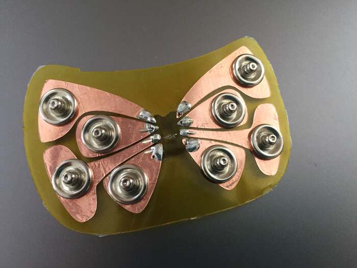
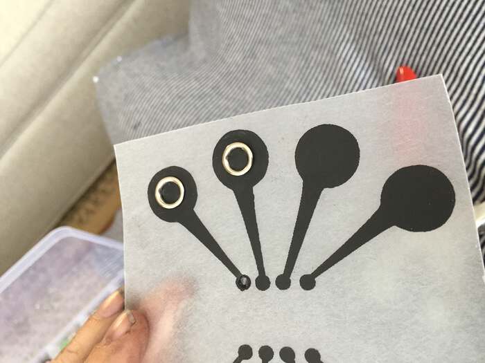
We combined techniques, ironing creative copper designs to a fabric substrate and using gripper snaps to affix a separate copper tape / kapton tape synth:
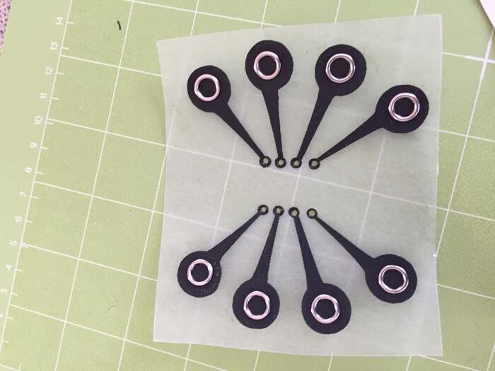
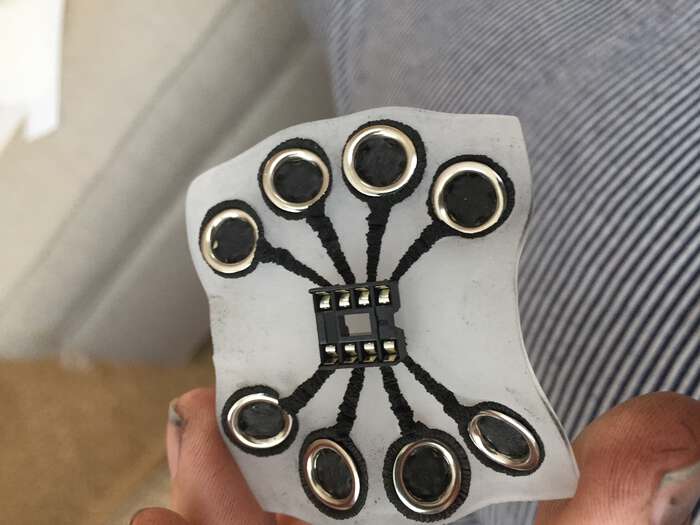
We also experimented a lot with different potential mechanisms for making more reliable connections between DIP socket integrated circuit packages and electronic textiles, including this gripper snap, kapton tape & copper tape butterfly connector:
We used the Cameo to cut Shrinky Dink and copper tape:
And, inspired by this research on shrinking circuits made with Shrinky Dink and conductive ink – in their case, a Circuit Scribe pen – we experimented with applying this method for our DIP socket adapters, using gripper snap buttons as well:
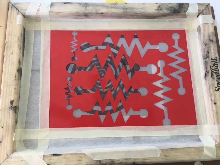
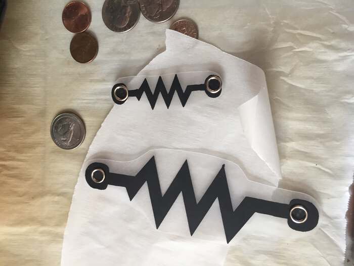
We also screen printed some resistors on Shrinky Dink and used gripper snaps to facilitate connections:
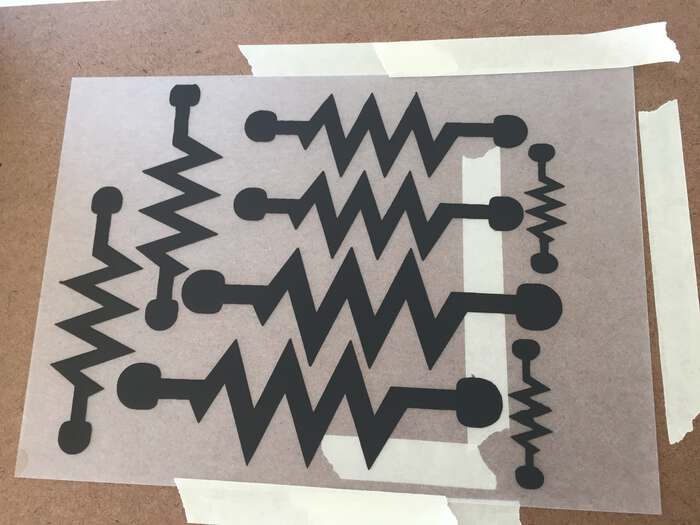
And here is a pinwheel synthesizer we made using a craft cutter:
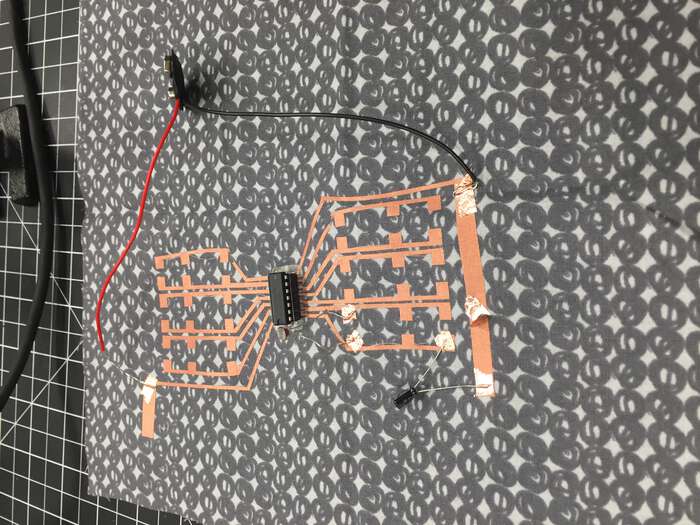
Before Fab Academy, while I had used craft cutters to cut copper tape on many occasions, the results were somewhat unreliable. During Fab Academy I learned that this was due to the poor adhesion of the copper tape to the backing it is sold on. If you transfer the copper tape to a different substrate before cutting, you get much better results. For example, check out this flexible astable multivibrator I designed in KiCAD:
Fab Academy Step-by-step Guide to Copper Fabric Cutting with Cricut
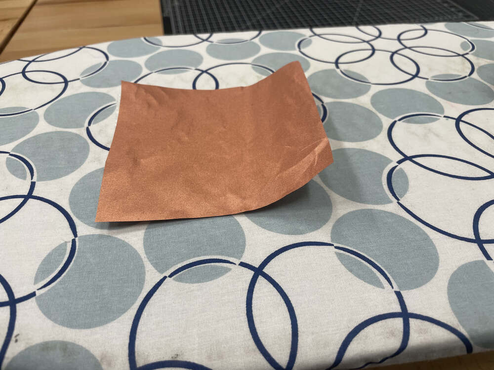
For this week’s assignment, I wanted to focus on documenting the process of cutting copper fabric with a Cricut. You will need copper fabric, regular fabric, heat-n-bond or another iron-on adhesive, an iron and ironing board, a Cricut, and a Cricut fabric-grip mat.
Begin by ironing a piece of heat-n-bond to the back of a piece of copper fabric.
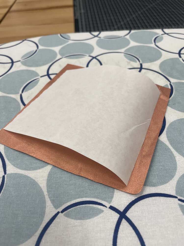
Flip over the heat-n-bond and copper fabric so that the copper fabric is laying on top. The place a piece of regular fabric atop the copper fabric for ironing;
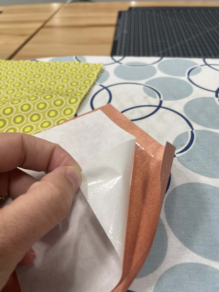
I used a piece of regular fabric on top of the copper fabric. I recommend making the piece of heat-n-bond just slightly smaller than the piece of copper fabric as this will help with weeding, later.
Copper fabric with backing adhered.
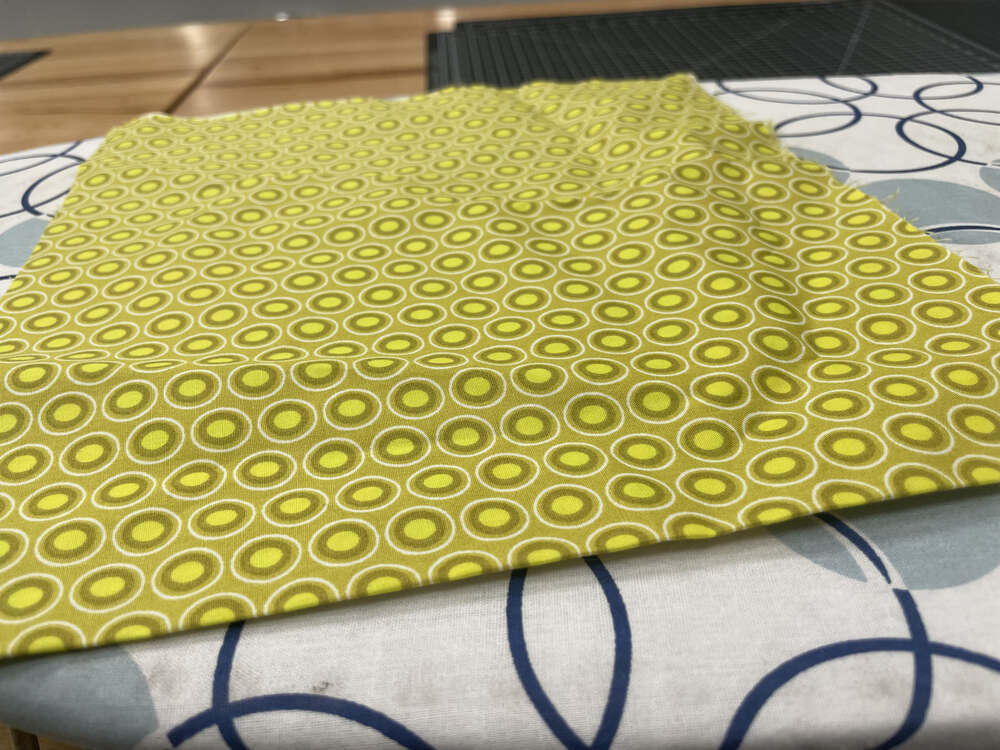
Next, gently iron the piece of copper fabric onto a regular piece of fabric, with the heat-n-bond facing down. Again, I put a piece of regular fabric on top. At this stage, you want the two pieces of fabric to be somewhat securely – but not permanently – adhered to one another.
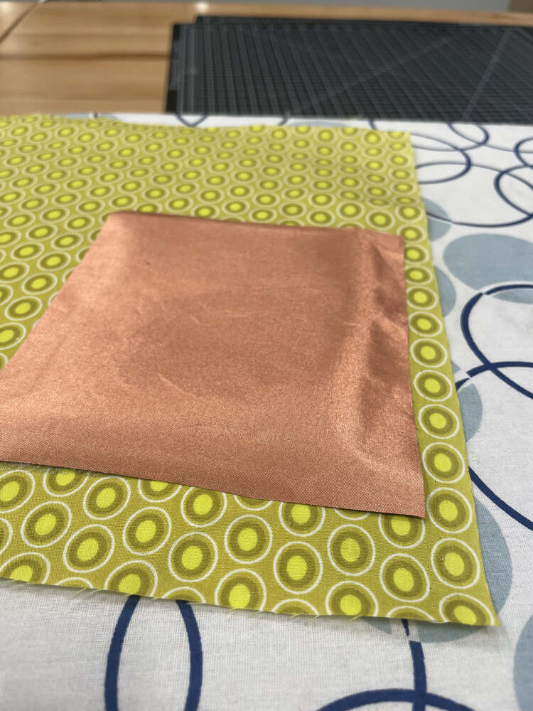
I mainly used the silk setting on my iron, but switched over briefly to cotton at the end. The goal here is to ensure that the copper fabric can be cut smoothly when sent through the vinyl cutter, without tearing up from its base, while also still allowing one to weed excess copper off the regular fabric substrate at the end.
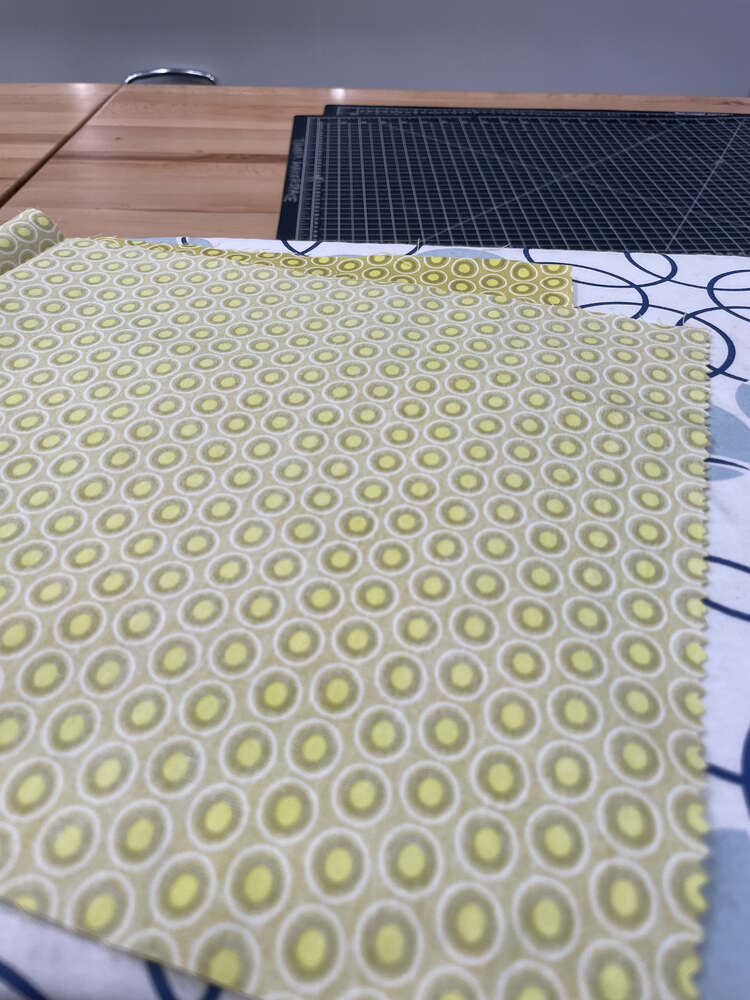
Next, load up your fabric onto a fabric-grip 12x12 Cricut mat and load up your design on the Cricut software.
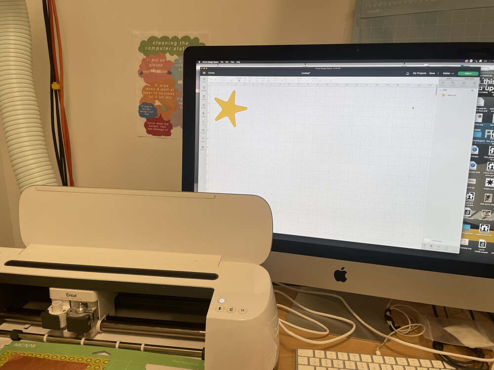
When you go to select the material, you will not find a ‘copper fabric’ setting. In my experience, choosing the vinyl setting but selecting ‘less pressure’ instead of normal pressure does a pretty good job of cutting through the copper fabric without cutting through the substrate beneath.
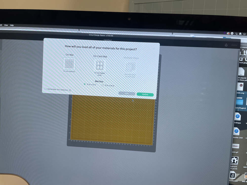
Setting mat:
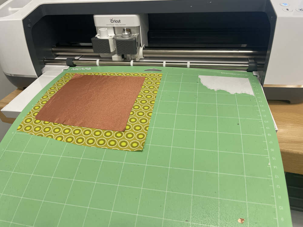
 Mat and cutting materials ready to go:
Note that occasionally, when cutting a conductive material on your Cricut, your machine may spontaneously shutdown. This is due to a build up of static electricity. The link provided has some troubleshooting tips. In my experience thus far, I have found that you may need to give your machine a moment, but it should eventually turn back on. Aim to keep materials nicely adhered to the mat and the copper fabric to the substrate to avoid it dragging around as that may generate more static electricity.
Note that alhough we are cutting fabric, I used a regular cutting blade, not a rotary blade, as is normal with the ‘vinyl’ cutting setting.
Cricut vs Cameo
Both companies cater to the home crafter. Each machine has its own pros
I have spent a lot of time with our vinyl cutters over the past few years since getting a Silhouette Cameo machine. Before Fall 2019, I knew about vinyl cutters but did not know about consumer grade craft cutters. From 2019 to sometime in late 2020 or maybe 2021, the craft cutter was the only machine we had in my studios. We’ve since gotten a 3D printer and desktop mill. But since it was the only machine we had, I got a lot of mileage. Pictured below are my own designs as well as collaborations with my current and former students - members of the crafting sound lab,–supported by Oberlin College and Conservatory. The Apple Amp and Orange Synth were developed in collaboration with Rachel Gibson, who led the original charge on campus for working with conductive fabric and for designing some of the first copper tape circuits we tried out here at Oberlin. That said, in case there is any doubt, I did a ton of this vinyl cutting, weeding, and application myself! The QR codes were in preparation for an assignment I gave my students to create Oberlin’s own rare meme collection. Pictured is my own weeding of a QR code. Still, it was shocking that my students still spoke to me after I had them weeding their own QR codes. You’ll also see conductive fabric with heat-n-bond backing and shrinky dink components inspired by this research.
fab22crnimefigs10.jpg fab22crnimefigs11.jpg fab22crnimefigs12.jpg
Additional Cricut Update
I have updated my vinyl cutting process on week 5 with some documentation of cutting traces for a copper tape circuit. I am including a description of the process below and also under week 5. For photos of the process, please check out week 5.
To begin the vinyl cutting process, you need a file to cut. While you can generate a file in the proprietary design software for Cricut or cameo craft cutters, in general these proprietary software tend to be cumbersome, and not particularly useful for creating your own designs. I recommend using an alternative software like Inkscape, or even drawing a sketch by hand to cut. Today, I’d like to begin with the process for designing and importing an SVG or scaled vector graphic into a proprietary software for the Cricut craft cutter.
You will find that certain images will be more effective to cut in a craft cutter than others. In general, if you are not creating her own design, you may want to begin by searching the web for silhouette images and particularly SVG files. You can also design your own files from scratch in ink scape, which by default it will save the file as an SVG. Both the cameo silhouette software and the cricket software have options for creating SVG files from bitmap images. In some cases you will find that there is a pay wall that might limit this functionality. If that is the case, note that escape has a really powerful trace but map feature, that you can use to create SVG files from that bitmap images.
Once you have an SVG file you should import it into the Cricut design software and import it into the workspace for your project.
You may find that you want to ungroup some of the objects that you have imported in order to make further edits in the Cricut Design Space software.
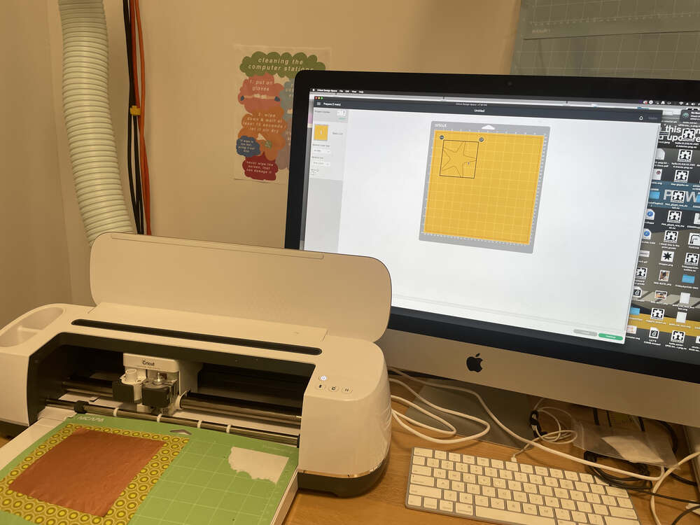
When you are ready to cut your image you should select the “Make it” option. However, you will find that while your design might look accurate in the design workspace workspace, when you try to cut it, different portions of the image that you have imported sometimes end up in unexpected locations. To fix this you will need to go back to your design workspace and select “weld” to ensure that your objects stay in their desired location when it is time to cut.
At this point, if you haven’t already, it is a good moment to prepare your materials for cutting. If you are using a Cricut machine, you will find that you typically will need to use a mat that for all cuts unless you are working with a proprietary smart Cricut material. As of this writing, in general, the Cameo is a bit more flexible, and that you can use any 12 x 12 sheet of vinyl without a mat. There are many different types of mats. You can find mats that are different sizes, as well as mats with different levels of stickiness that are suited to different material types. You will want to begin by choosing the correct mat for you material, and then laying down the material according to where you have placed your design in software. In general it is useful to align material and software designs to the left corner. If you are cutting a special material like copper tape, you will find that you need to transfer the tape to the material you would like to ultimately have the tape on. This is because the backing that the tape comes on originally has very poor adhesion, and as your vinyl cutter cut the tape if it is on its original packing the blade will pick up the tape as you go.
Once you have placed the material you want to cut on the mat you loaded into the vinyl cutter. Turn on the machine and make sure that it is connected to your computer. In the software you will need to indicate the material you are cutting. Copper tape can be cut on a standard vinyl setting. After you have chosen the cutting material in software, you will be asked to press the button on the machine which will load the material into the machine and measure it before the cutting begins.
After you cut the vinyl or other material you can remove the material from the machine and the mat. The process that occurs next is weeding the vinyl. To weed the vinyl you remove the excess material that you do not want to have included in your design. Next you use clear transfer tape to pick up the design as you want to transfer it and to place it onto a new substrate. Throughout the weeding process, it is important to ensure that you are only removing materials that you would like to remove. When transferring the material to a new substrate you will want to ensure that you check that the material as level and use an ID card or other hard surface to help lay down the vinyl and ensure that it sticks onto the new surface.