4. Computer Controlled Cutting
The group assignment this week was focused on getting to know our laser cutters and vinyl cutters. Our lasers are from Epilog and our vinyl cutters are from Roland.
Useful links to our Student Sites for this group assignment
Group Assignment
- characterize your lasercutter’s focus, power, speed, rate, kerf, and joint clearance
- Document your work to the group work page and reflect on your individual page what you learned
Equipment Description
Abby and Jim are working in remote locations and they collaborate by communicating through Zoom and Mattermost while working on their local cutting machines.
Laser Focus
While some laser cutters have manual focus by rotating the lens, the Epilog laser is focused by varying the distance from the material being cut or etched. The Epilog laser has a measuring tool and a convenient auto focus that can be used prior to each cutting job. In manual mode a measuring tool is used during adjustment, and then removed. In automatic mode, a plunger senses contact with the material surface; the table automatically adjusts based on the plunger input.
Laser Speed, Power & Rate
Speed, Power & Rate: Epilog Helix has a table of Suggested Material Settings in Appendix B; these parameters are adjustable on the physical control panel as well as through software settings. The best way to learn is to try different materials and varying the speed, power, and frequency. Depending on wattage of the laser tube, most materials and thickness are listed with recommended settings; it is best to start with these settings and varying them after testing.
Laser Kerf
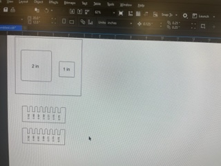
As Abby mentions in her documentation, “When laser cutting, some amount of material is lost due to the physical properties of the laser–and to some extent, the properties of the materials being cut. The amount of material lost in the cut is the kerf.” Abby measured the kerf, by creating a one inch square and a two inch square in Inkscape, brought it into CorelDraw, cut it on the laser cutter, and then measured around the outside of each square and also the negative space remaining from each cut.
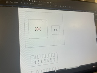
Jim used the following Kerf Gauge
The center square is 1.000 inches on each side; the other squares have several thousandths added to their sides to make them digitally larger than the center square. The square that fits in the center best, after cutting, shows the kerf of the laser. Varying the speed and power of the laser will change the kerf in each of the different materials.
Laser Joint Clearance
Joint clearance is related to the kerf of the laser; to ensure the best fit, the joints must be designed to account for the kerf of the laser for the type of material being used.
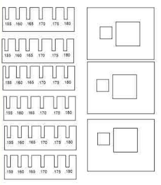
Abby worked on the joint clearance assignment. She measured the thickness of the cardboard on hand and then created a comb with the spaces between the teeth dicated by the measurement taken. Abby used both the initial measurement and then also some smaller measurements to create these spaces to see what might make the most snug fit.
Group Project
Below is some additional documentation from the LCCC branch of our remote collaboration:
Our group assignment is to characterize your lasercutter’s focus, power, speed, rate, kerf, and joint clearance and to document your work to the group work page and reflect on your individual page what you learned. I am copying some documentation of the group assignment below because we are getting a 404 error on the group page. However, it is also uploaded to the group repo!
From my fellow LCCC co-hort member Jim Hart’s site, I found the LCCC Group page from a few years ago. I used this page to better understand the scope of the group assignment and recreated the files they used for testing Kerf and joint clearance. One note I’ll mention is that Jim and I are working together remotely…so we are using different machines and are on different schedules. But we have been doing our best and I am learning a lot from reading Jim’s repo. So, our group work is asynchronous and remote. Sometimes I use ‘I’ in the group documentation but please know that it is a group effort.
When laser cutting, some amount of material is lost due to the physical properties of the laser–and to some extent, the properties of the materials being cut. The amount of material lost in the cut is the kerf. To measure kerf, I created a one inch square and a two inch square in Inkscape, brought it into CorelDraw, cut it on the laser cutter, and then measured around the outside of each square and also the negative space remaining from each cut. You can see these images below:
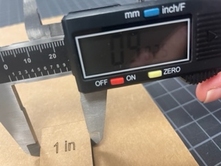
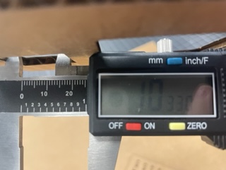
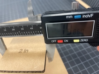
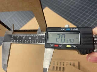
I only measured on one side for each square so my values may be a bit less precise but should give a close idea of the kerf. For the two inch square, the kerf is 2.034 - 1.986 = 0.048 inches. For the one inch square, the kerf is 1.033 - 0.9025 = 0.1305. The average kerf would therefore be 0.08925. This seems large to me, compared to the average the previous group found of 0.015 inches. My guess is that either the calipers were having issues – the battery seemed very low – or else perhaps my equipment settings were significantly different from the previous group.
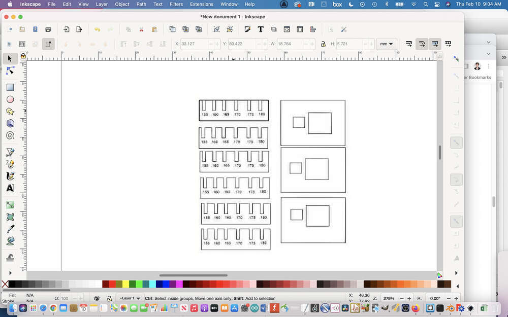
Subsequently, I worked on the joint clearance assignment. I measured the thickness of the cardboard on hand and then created a comb with the spaces between the teeth dicated by the measurement I had taken. I used both the initial measurement and then also some smaller measurements to create these spaces to see what might make the most snug fit.
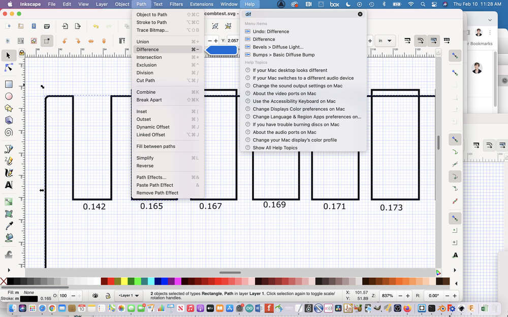
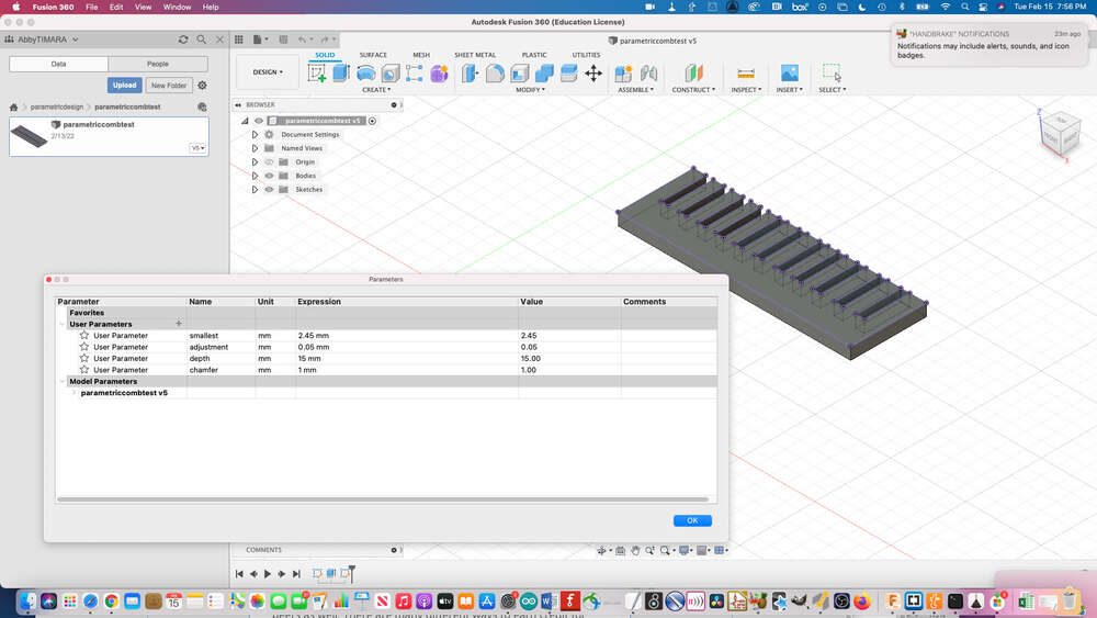
Below is an image the file I created – I initially made it in Inkscape but after I moved it to the lab machines and imported it into Corel Draw it still needed a bunch of work. This process was a bit slow because I was not yet working parametrically, originally. Later, I made a parametric version in Fusion. I go into much more detail about parametric design below, so hopefully that will suffice for illustrating how I worked parametrically. I made the second comb in a bit of a rush at Think[box] and did not have time to properly document it.
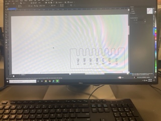
Here was the first version of making the software comb as it was being built:
I used the difference tool to cut excess lines:
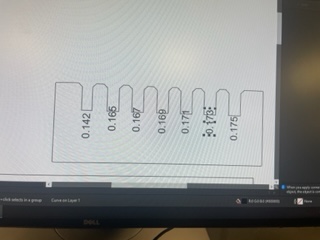
 This is me adjusting it further in Corel Draw.
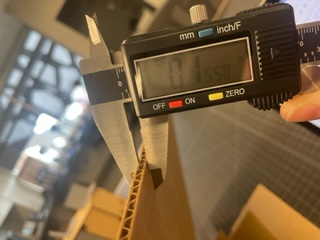
To do the comb joint test, you need to decide on a range of values to use for the joints. We measured our carboard to determine the widths to test:
Here is the finished version in CorelDraw:
And here you can see the whole file:
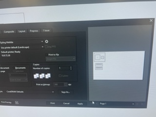
LCCC uses CorelDraw to send materials to the Epilogue software, so you have to optimize your files for CorelDraw:
Here is the parametric version in Fusion:
The original LCCC group documentation:
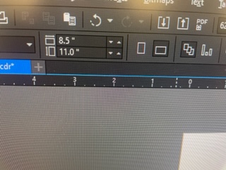
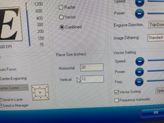
In Corel Draw, which is the program we use to talk to the laser cutter, it is important to tell the laser cutter the correct size of the material you are going to use:
First measure the size:
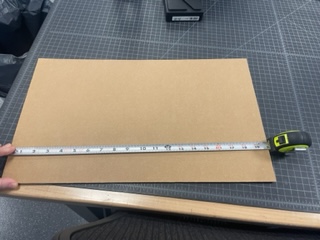
Then enter the values into the software:
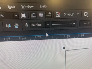
It is important to make sure that everything you want to cut is set to hairline:
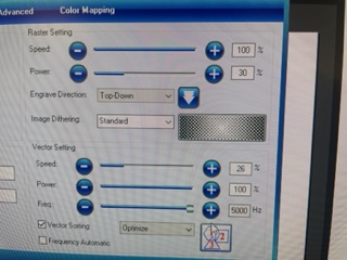
In the Epilog software dialogue, you can define all sorts of settings including what you want your laser to do, The first time around, we set it to combined raster and vector, since we wanted to cut the comb and also see the size of the cuts rastered on the cardboard. This took forever and wasn’t super effective, so we subsequently used vector scoring instead.
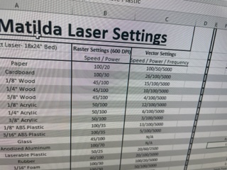
You also need to assign settings for speed, power, and frequency based on the materials you are using. Thankfully, LCCC has a handy cheat sheet so we knew what settings to use for cardboard.
Here we are checking to see if the comb and kerf tests are set to be in the proper defined area:
Here is the final digital file:
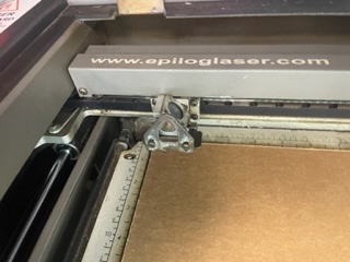
Now it is time to use the laser cutter!
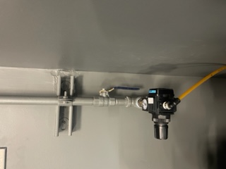
It is important before running the laser cutter to make sure that the airflow is on:
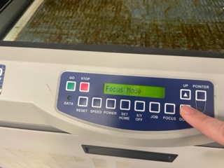
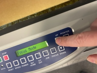
Using the laser cutters user interface in focus mode to raise and lower the bed to adjust the laser focus.
First you need to flip the little magnetic autofocus tool down.
Then you need to adjust the height of the bed until it just touches:
Continuing to adjust the focus but now I raised the bed:
To exit focus mode you hit the reset button:
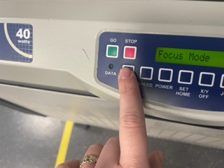
And then when you see your file name, you can tell it to go!
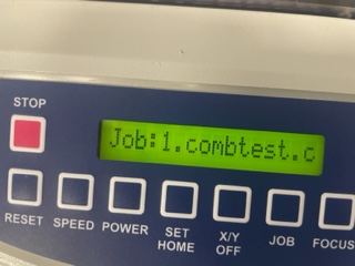
We cut the materials!
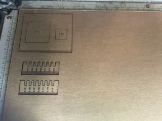
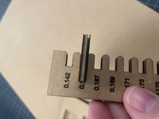
Here is a close up of the laser cut comb with vector-scored measurements:
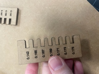
It fits! 0.165 was the magic number.
During global open time, Adrian showed his example file where they tested the speed and focus for the laser cutter. It looks amazing and you can find it here. I didn’t get to test this because I didn’t have enough time at the lab. I hope to be able to test it subsequently.