Machine Building
Please find our project video here:
We will compress and add it directly to this page subsequently.
The group assignment this week was focused on Mechanical Design and Machine Design.
Useful links to our Student Sites for this group assignment
Group Assignment
Mechanical Design (part 1 of 2) - Design a machine that includes mechanism + actuation + automation - Build the mechanical parts and operate it manually. - Document the group project Machine Design (part 2 of 2) - Actuate and automate your machine. - Document the group project
Learning Outcomes
- Work and communicate effectively in a team and independently
- Design, plan and build a system
- Analyse and solve technical problems
- Recognise opportunities for improvements in the design
Communication
For this assignment we discussed possible machine ideas using Zoom and email for communications. We communicated with Scott, our instructor, through email to keep him informed of our ideas and progress. One idea was a cd player with vinyl cut designs on old cds that are read in to transform color to sound. We discussed this with Scott; he gave an example of designing and building a machine to load and unload CDs. He also mentioned that the typical project uses an off-the shelf controller to drive 2 or more stepper motor driven axes. Scott suggested a machine based upon 2 linear axes and an End-of-arm-tool (EOAT) designed to perform a certain purpose. We decided to use Cardboard Stages and have an EOAT to pick up magnetic distortions to make sound through the use of an amplifier.
We used what materials and parts were available at LCCC; specifically, stepper motors with lead screws built in. For the controller Scott suggested an Arduino Uno with a Stepper motor Shield; Jim ordered the controller parts so he could prototype and program the controller at his remote location.
Design, plan and build a system
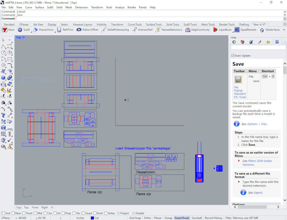
- Design - Using the Rhino Model provided by Nadya Peek, we planned to configure a simple 2 axis stage to move our magnetic pickup over a surface area.
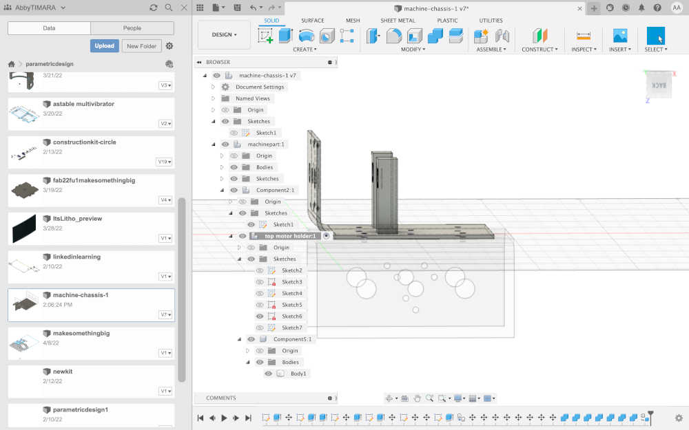
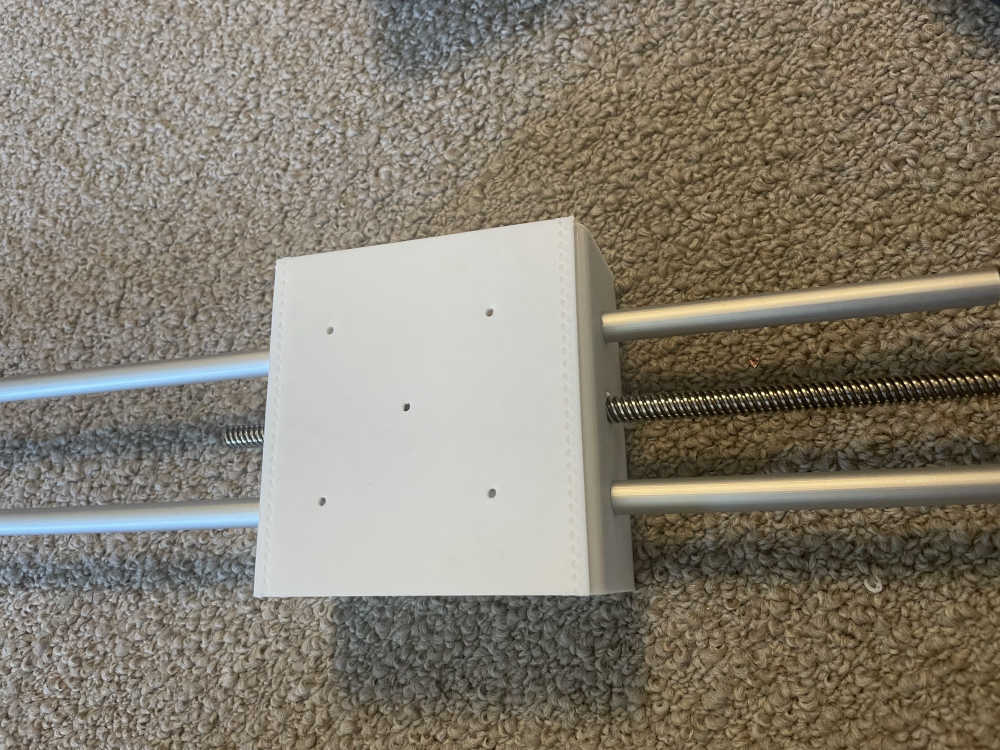
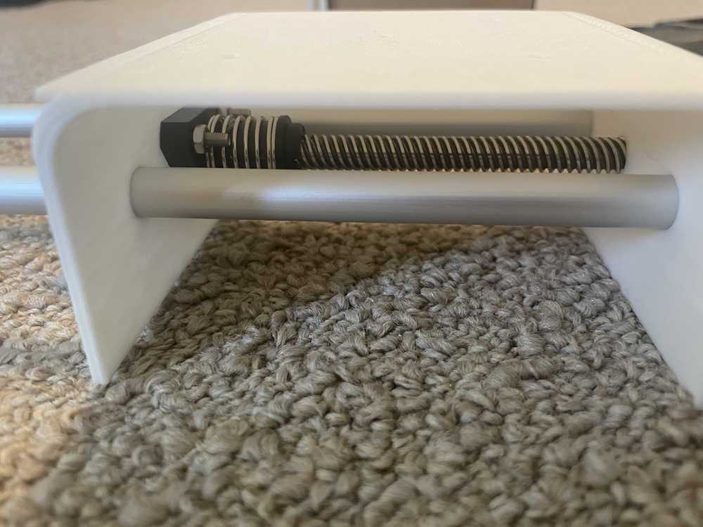
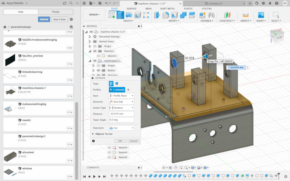
3D Print Design - The new direction taken was to design and 3D print the stages. Abby took the initiative to design in Fusion 360 and was very successful in designing and 3d printing this part. We decided to just 3D print most of the body with a bunch of smaller pieces instead of the longer cardboard sections.
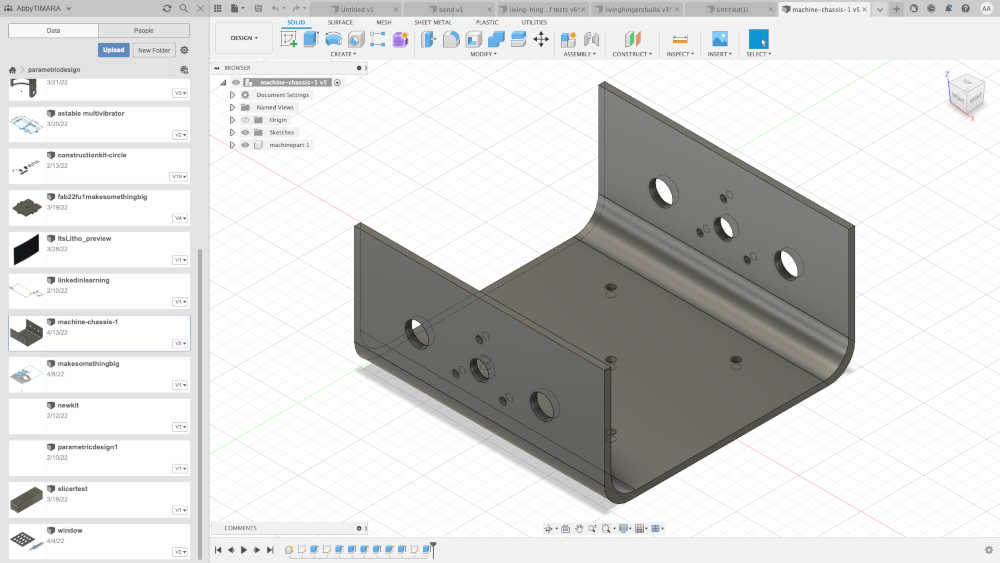
Design of the first stage.
Spiral Development!
-
Plan - Jim used the Rhino files and exported the model from Rhino to Sketchup for further 3D design. He exported the cut files to Inkscape to make the cut files. Abby planned on using the files to cut the cardboard with a laser cutter; as mentioned above, she decided to model and 3D print the stages intead of cutting them. The magnetic pickup will be made by Abby as well as the magnetic field generators for the surface area. Jim will use his controller and stepper motors to bench test and prototype the concept with his xy plotter; the software will be developed in the Arduino IDE.
-
Build - Stages, Controller, Pickup, and Sound
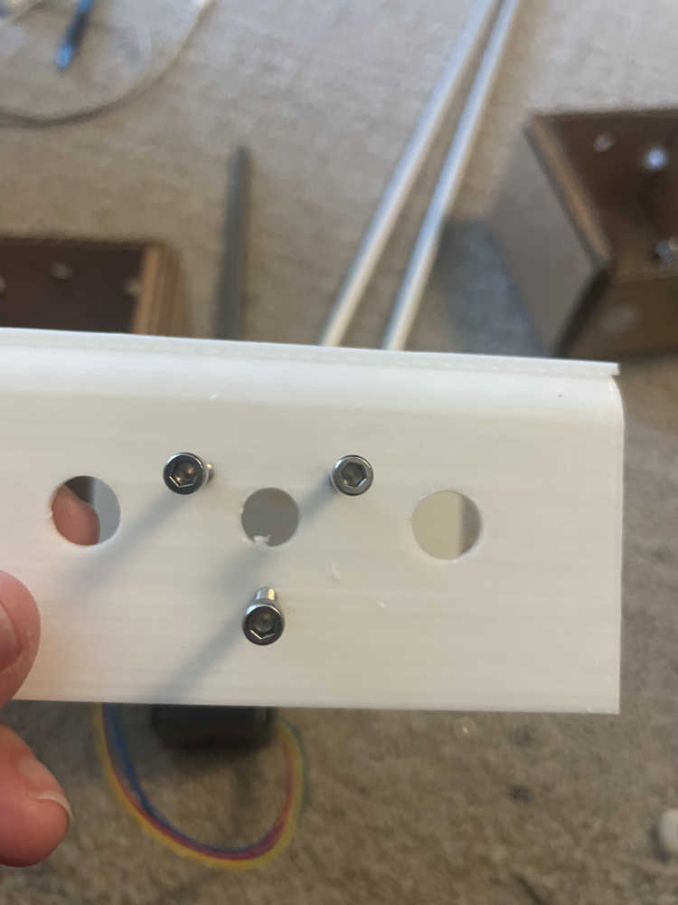
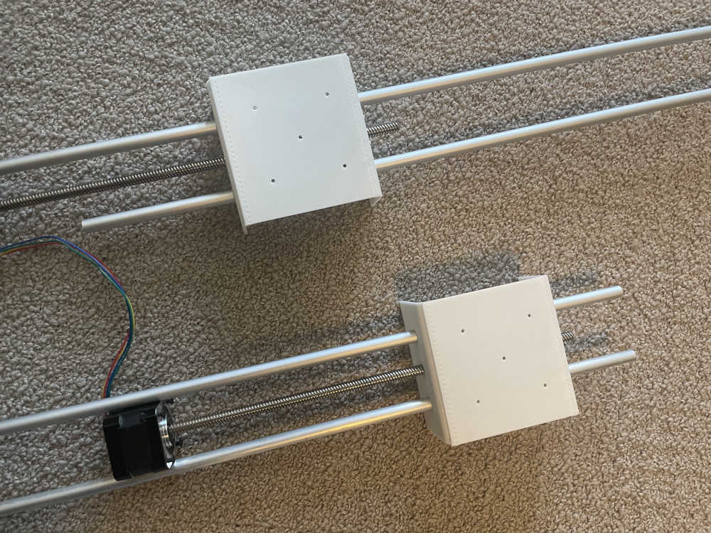
Stages - Abby printed two moving parts and assembled them.
Spiral #1
Spiral #2
Spiral #3
Spiral #4
Analyse and solve technical problems
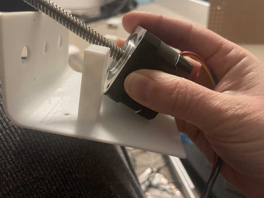
The motor mount size was not correct, so Abby went back to make a better design.
Success!!
Controller - The Kuman CNC Kit has documentation on the website. I also watched a YouTube video by Electronic Clinic to help build the kit; there is also a written version of the instructions here I assembled the controller per the video and the instructions.

Controller Preassembly
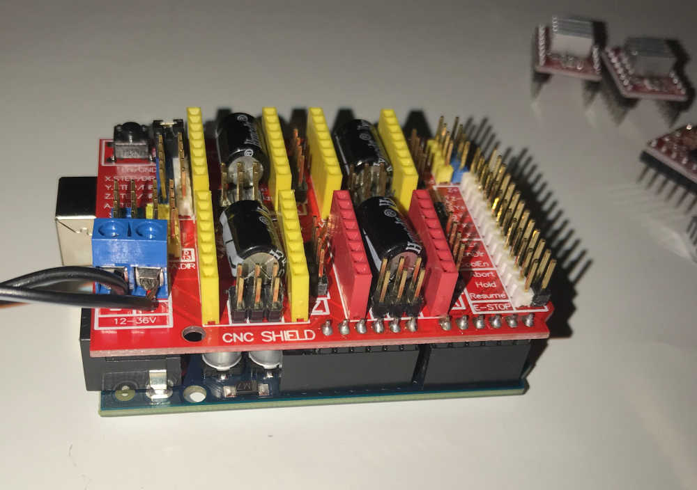
CNC Shield attached to Arduino UNO
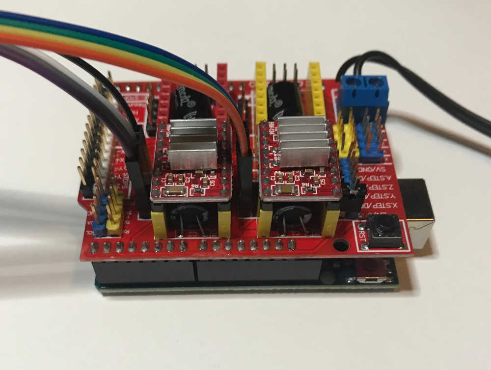
Controller wired to accept stepper motors
Controller connected to stepper motors and ready for testing
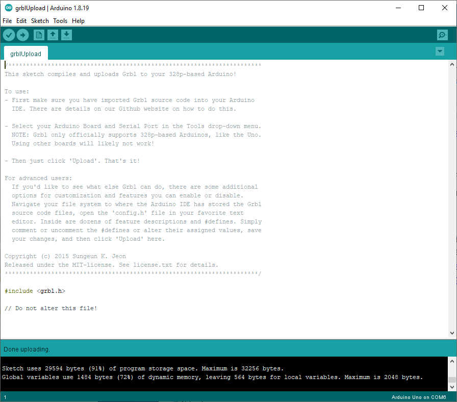
The Arduino IDE accepted the GRBL Library and uploaded the software flawlessly.
The instructions recommended Universal G-code Sender, so I downloaded and extracted the files. I ran ugsplatform64 located inside the bin directory, refreshed the Port and COM6 showed up,
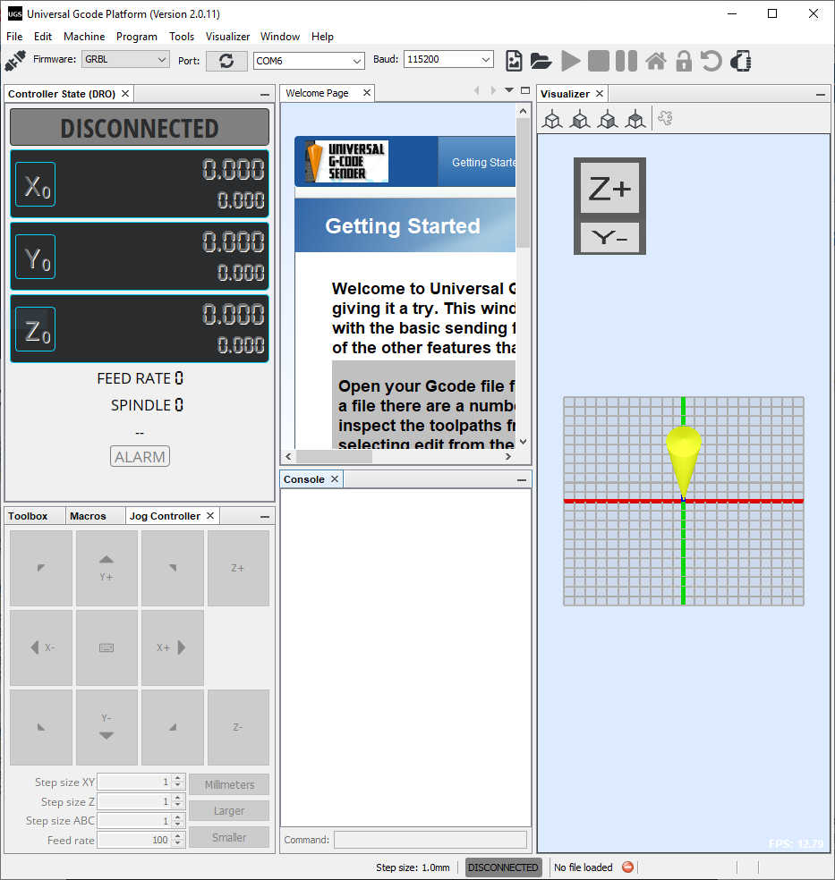
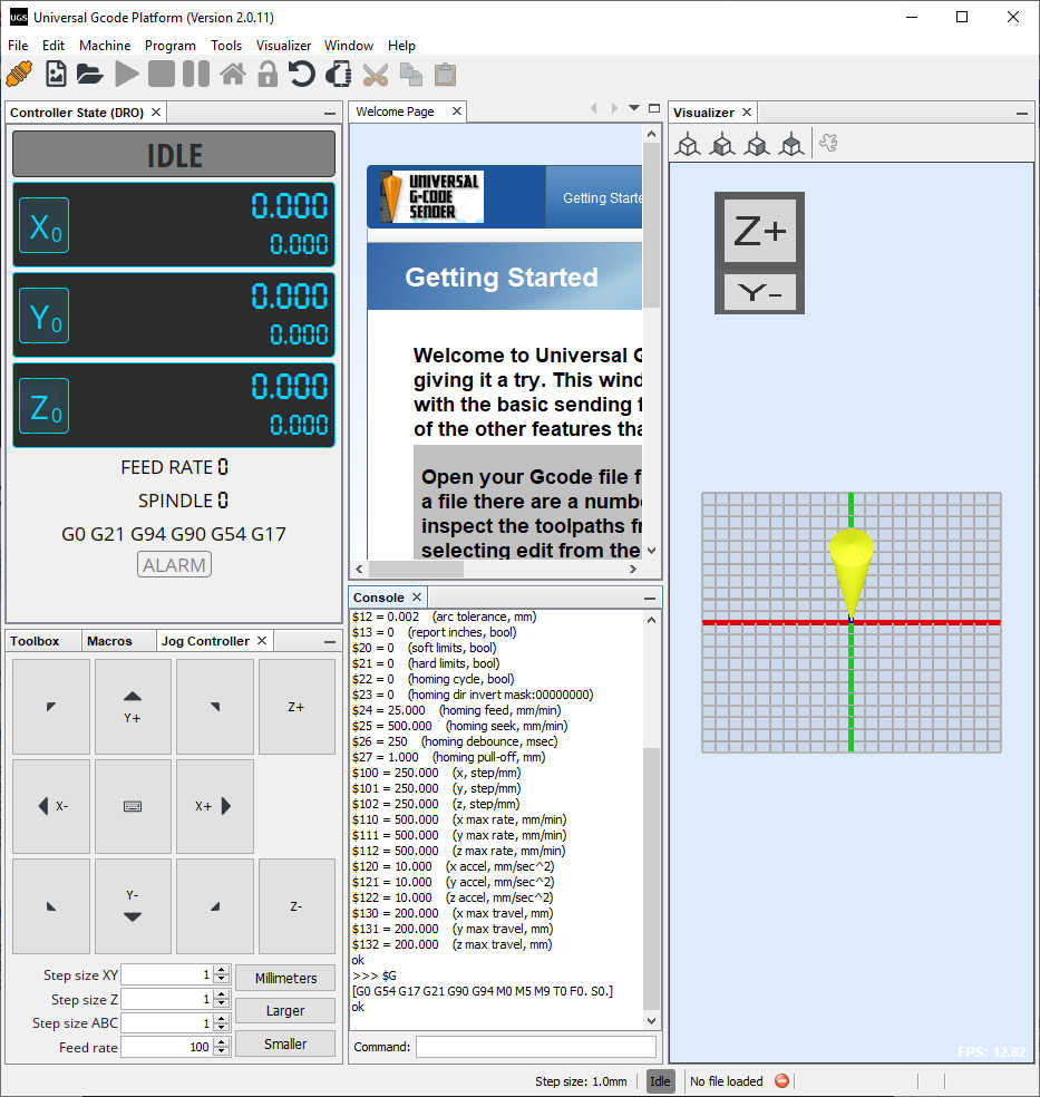
I clicked Connect and successfully connected to the Arduino and saw the G-code.
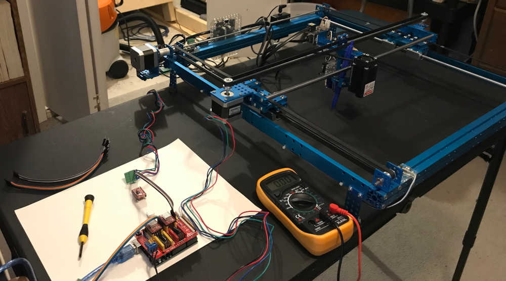
Analyse and solve technical problems
I had a problem with the first stepper motor driver; the x-axis stepper motor would not turn. I thought it may be the software, so I tried the ino code provided by Electronic Clinic, still no movement. I placed a different stepper motor driver in the socket and had success. I checked the Vref voltage and found it at 0.56 volts by using the negative power connection as a common and touched the potentiometer with the positive lead. I put the other stepper motor driver back in the socket, turned the potentiometer until the stepper motor responded, and then adjusted Vref to 0.87 volts. After properly adjusting the Vref, the stepper motors were very responsive. I tested the x-axis and y-axis movement successfully.

Tested with UGS
Tested with Arduino Sketch
- Mechanism and Manual Operation
Build the mechanical parts and operate it manually
Abby assembled the 3D printed stages and installed the hardware and motors; she operated it manually to ensure that the movement would be correct.
- Actuation
Actuation was performed using the Arduino Uno/CNC Shield/Stepper Motor Driver controller to drive the X and Y stepper motors. The end effector was an electomagnetic pickup fed into an amplifier and played on a speaker. The motion of the motors provided the magnetic waves necessary to make noise.
- Automation
Automation was accomplished by sending g-code to the controller using Universal G-Code Sender software. Jim made a spiral.svg file in Inkscape, resized it in Illustrator, opened the svg file in LaserGRBL and saved the nc file. Once opened in UGS, the nc file was sent to the controller and produced the desired noise by automatically driving the stepper motors. It sounded pretty cool 😎
Results
After my testing on the XY Plotter using the same CNC controller, I sent the Little_Spiral gcode to Abby and she sent uploaded it into her CNC controller. This is the result.
During the video, Abby sent the spiral2_5.nc file to the controller. The sound was generated and sent to the speaker. You need to see/hear the whole clip. At the end, Abby said, “that was the little spiral.” :)
To show the path followed by the machine, Jim used his XY Plotter, driven by the same controller used in our machine.
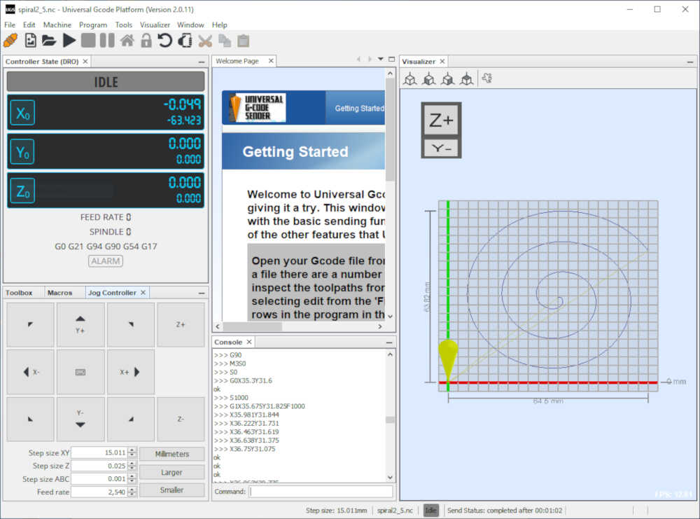
Little spiral in UGS as G-code.
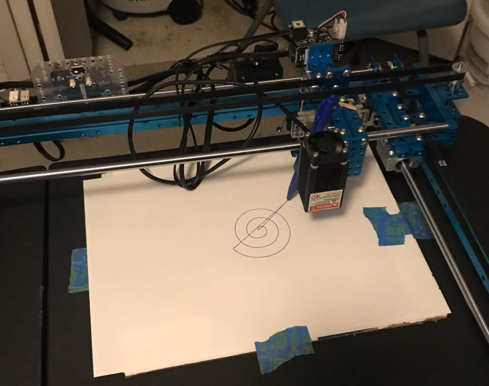
XY Plotter shows the path in ink.
Grand Finale
Future Developments
This was a great learning experience in making machines that make noise. In the future this machine can be made more stable and more precise in making sounds and noises that are repeatable in loops. Spiral Development!
Included your original design files:
-
This is a list of our original design files discussed on this page:
-
2D Vector
-
Adobe Illustrator Scaled image of spiral spiral25.svg 1.9 Kb
-
Inkscape Original spiral made in Inkscape spiral.svg 2.6 Kb
-
G-Code Sent to controller through UGS spiral2_5.nc 6.8 Kb