6. 3D Printing and Scanning
The group assignment this week is to test the design rules for your 3D printer(s) We have two different printers: the Ender 3 Pro and the Afinia H800 3D.
Useful links to our Student Sites for this group assignment
Group Assignment
- Document your work and explain what are the limits of your printer(s)
- Document your work (in a group or individually).
- Document your work to the group work page and reflect on your individual page what you learned.
Learning Outcomes
- Identify the advantages and limitations of 3D printing
- Apply design methods and production processes to show your understanding of 3D printing.
- Demonstrate how scanning technology can be used to digitize object(s)
Research
For this assignment we researched and worked with our 3D printers individually. Jim used the Afinia H800 3D this cycle. Abby used the Ender 3 Pro.
3D Printer Limitations
This week’s lecture covered several of the constraints / limitations one encounters when working in additive manufacturing. On the Fab Academy site, Neil provides a collection of helpful quick 3D prints that help to illustrate several limitations of 3D printers. You can also find a lot of example prints on Thingiverse and other sites that address some of these same limitations. For this week’s group assignment, Abby used Neil’s files while Jim branched out to examples found on other websites.
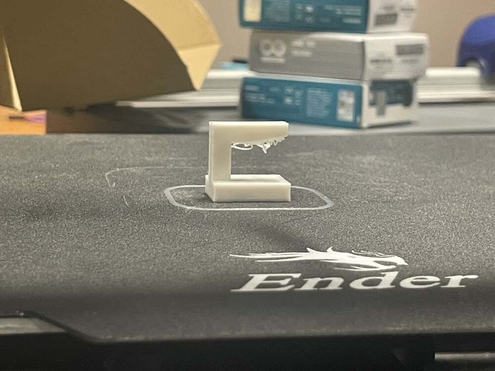
The first STL file that Abby printed was a small piece with a hard right angle that was unsupported. The underside of the unsupported section clearly failed as a print and illustrated the importance of supports or alternative design features to ensure better outcomes. That said, in reviewing the work of other Fab Academy students, it seems that some higher end printers might have more success with this particular challenge, so the precise limitations are clearly printer-dependent.
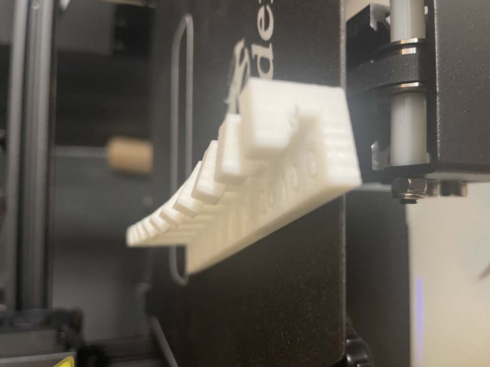
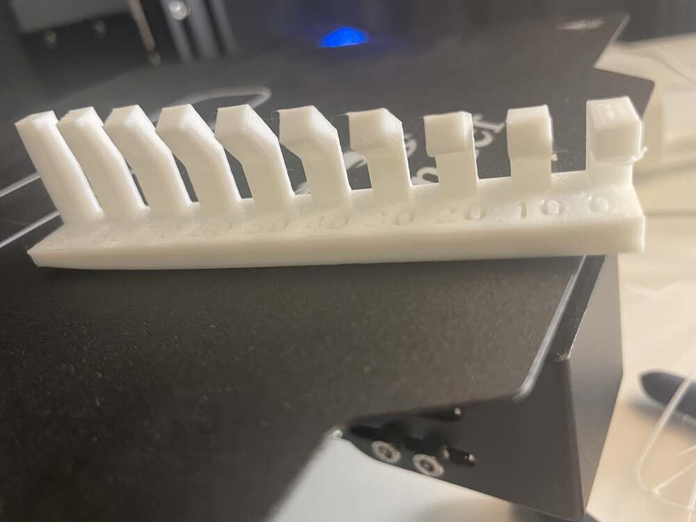
There are three test files illustrating related concepts: The angle print is a series of overhangs printed along a row at progressively smaller angles until it reaches 90 degrees. The overhang print represents progressively longer overhangs. The bridge file contains progressively longer bridges. Each of these prints illustrates limitations and/or potential design solutions relating to printing at 90 degree (or similar) angles. The angle print allows us to check the angle at which our 3D printer will begin to fail. The overhang print allows us to determine the maximum possible length of an unsupported right angle. The bridge file allows us to see how the length of an otherwise unsupported right angle printed can be successfully extended when the opposite side is supported (even where the middle is not supported).
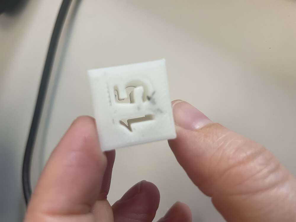
The next print Abby tried was the 15% in fill. However, she accidentally printed the example at 10% rather than 15%. My instructor subsequently demonstrated to me how to change several of the settings in the Creality Slicer 3-D print software. I hope to reprint the infill test at 15%; The original print was completed at 10% infill. The infill setting will impact the speed of the print, the weight of the final object, as well as its structural integrity.
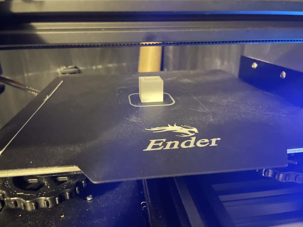
The cube print listed measurements of 10 and 20 mm. Abby did not understand what this print was supposed to convey until one of our instructors helped her to understand that she needed to measure the inner and outer diameters to determine whether the 3D print was true to size. We measured the print with calipers and discovered it was very close to correct on both the inner and outer measurements.
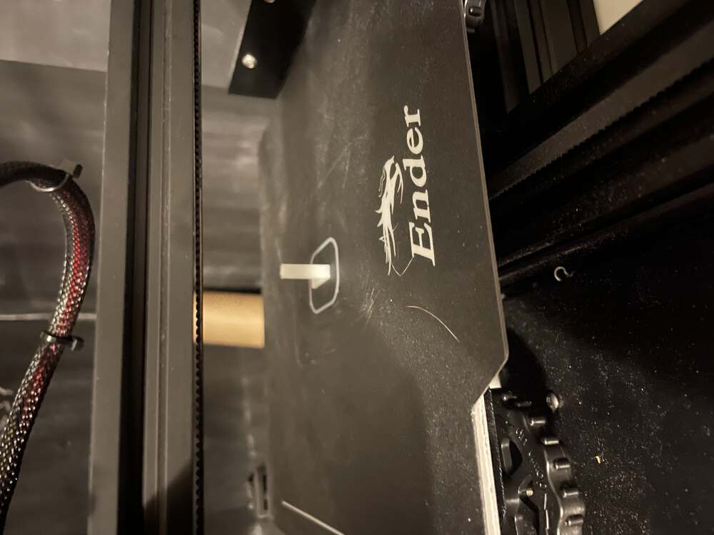
The right angle print has a long base and a skinny vertical print area. Our instructor said that the small print area of the vertical element could be problematic for some printers because the PLA might not have enough time to cool down if the print head is constantly moving back and forth over this area.
The finish test came out very oddly for Abby’s printer and our instructor was initially very confused by the poor quality. Abby did not have her printer with me in the lab, but our instructor was able to hypothesize, correctly we think, that one or more of the belts on Abby’s printer is likely loose.
In a previous year, Jim printed the Benchy model as a test. This year, he found a cool 3D print test on Thingiverse that tests many of the same elements of the 3D printer in one print, likely saving loads of print time!
Results
We were both able to print tests on our respective 3D printers that helped us to better understand the constraints associated with additive manufacturing. These constraints have to do with the limitations of the machines and fabrication processes. It also helped us to understand how simple calibration issues can cause less than satisfactory printing results. Supports and other tricks deployed in the slicing software, along with close attention to calibration, can help mitigate issues. However, it is even better to keep in mind the design constraints of 3D printing when designing a CAD model for printing in the first place.